Ellis,J. Pressure transients in water engineering, A guide to analysis and interpretation of behaviour
Подождите немного. Документ загружается.

jdV=dt
d=s
j < jdV=dt
u=s
j. Corresponding changes in transient pres-
sure are also reduced and piezometric level at the tank connection
is determined by the relationship:
H
tank
H
main
¼
X
K
L
þ 1
no
Q
2
=ð2gA
2
c
Þð15:2Þ
262
NRV open
(a) (b)
(c) (d)
(e) (f)
NRV open
NRV open
NRV open
NRV closed
NRV closed
H
u/s
H
d/s
H
u/s
H
u/s
H
u/s
H
d/s
H
u/s
H
d/s
H
d/s
H
u/s
H
d/s
H
d/s
M
M
M
M
M
M
M
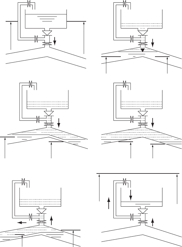
Fig. 15.3. Operating sequence of feeder tank
Pressure transients in water engineering
where A
c
is the cross-sectional area of the outflow connection and
P
K
L
is the sum of loss coefficients for the components making up
this connection — that is, entry loss, NRV loss, tee, isolating valve
and pipe resistance. The feeder tank supplies treated water from the
tank to the main, thus minimising risk of contamination.
Characteristics are selected which arrive at the feeder tank
connection at the time when a solution is required. The quasi-
invariant values propagating along these paths yield a pair of
equations at the feeder connection so that:
V
u=s
þ g=aH
main
¼ Jþ and V
d=s
g=aH
main
¼ J
These equations can be solved for V
u=s
, V
d=s
, H
main
and H
tank
for
normal operation.
(b) After the feeder tank and its connection have drained, initially a
common water surface and piezometric level will exist upstream
and downstream of the feeder connection. Conservation of
volume is given by:
V
u=s
A þ Q
air
¼ V
d=s
A þ A
s
dz=dt
where A
s
is the air—water interface area in the pipe and
z ¼ z
u=s
¼ z
d=s
is the water surface level.
(c) If the downstream water level should fall then a situation may
develop where upstream and downstream water levels become
different so that:
V
u=s
A ¼ A
su=s
dz
u=s
=dt þ q
and
V
d=s
A ¼ q A
sd=s
dz
d=s
=dt
where q is the spillage from upstream to downstream.
(d) If a pressure vessel at an upstream pumping station is refilling, velo-
city upstream of the feeder connection may reverse, causing the
water level to decline on this side of the feeder connection, then:
q ¼ 0:0
(e) If downstream flow should reverse, spillage may occur from down-
stream to upstream of the feeder connection, so that:
V
u=s
A ¼ A
su=s
dz
u=s
=dt þ q
and
V
d=s
A ¼ q A
sd=s
dz
d=s
=dt
263
Feeder tanks or volumetric tanks
(f ) During refilling water enters the feeder tank via the modest-
diameter filling connection. Inflow is regulated by a valve which
closes in response to rising water level in the tank. As level
increases, the valve progressively closes so that a quiet shut-off of
inflow is achieved as the tank level approaches top water level
(TWL).
15.3 Abnormal behaviour
A case involving abnormal feeder tank behaviour occurred after pump
trip in a treated water pumping system comprising a prestressed con-
crete rising main, diameter 1070 mm and length almost 16 km. As
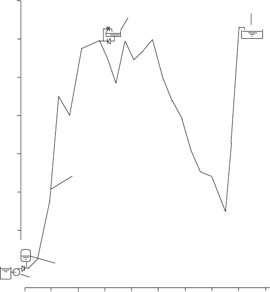
can be seen in Fig. 15.4, the main has an unfortunate profile as regards
avoiding sub-atmospheric pressures. To provide adequate protection at
264
0 2 4 6 8 10 12 14 16 18
Elevation (mAOD)
Downstream reservoir
Feeder tank location
Pipeline profile
Pressure vessels
Pumping station
Chaina
g
e (km)
1070 mm diameter prestressed concrete pipeline
Stanton steel cylinder type – 15 796 m long
190
180
170
160
150
140
130
M
M
M
Fig. 15.4. Feeder tank on a rising main with pressure vessel
Pressure transients in water engineering
the pumping station in the form of pressure vessels alone, necessary
capacity would have been extremely large. A feeder tank of capacity
75.1 m
3
, TWL of 183.354 mAOD and tank outlet level of
180.495 mAOD was provided at chainage 5.4 km. Surface area of the
tank was 26.267 m
2
. The outlet connection had a diameter 381 mm
and a filling connection diameter of 127 mm.
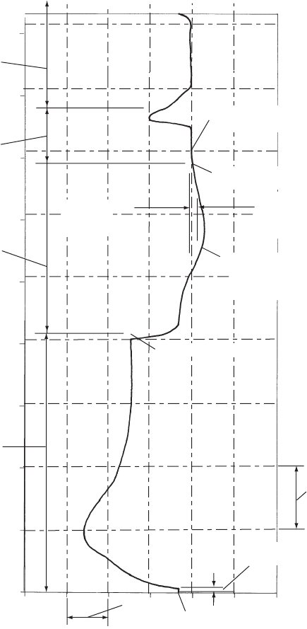
Figure 15.5 shows the predicted variation of piezometric level at the
feeder connection for a simulated pump start/stop operation. A 16 mgd
(million gallons/day), (73 Mld) pump was started and run until steady
flow was attained after around 4 min when the pump was tripped.
The feeder tank came into operation 30 s after trip, emptying after
150 s. This prediction was confirmed by field observations. A peak air
volume of 4.52 m
3
was calculated to develop in the pipeline 210 s
after pump trip. After flow reversal in the downstream section of
pipeline, the check valve on the outflow connection closed and the
air pocket was expelled through the filling connection. When water
started to pass through the filling connection the sudden increase in
flow resistance caused a modest head rise to occur and a deceleration
of the reversed flow in the downstream pipeline.
The pressure vessels at the pumping station reached their maximum
expanded air volume and started to refill about 90 s after pump trip.
Until this time the feeder tank had only been supplying water to
maintain positive flow in the downstream pipeline. When the pressure
vessels started to refill, the feeder tank provided the most convenient
supply of water for the vessels and so for a time this tank supplied water
both to the downstream pipeline and also to the upstream pipeline for
vessel refilling. The high demand during this time is responsible for the
rapid drawdown in feeder level. The tank outlet diameter is relatively
modest for this high rate of outflow and substantial head loss was
experienced leading to a sub-atmospheric pressure head of 4.0 mWG.
If the feeder tank forms a part of an overall protection package which
includes a pressure vessel installation at an upstream pumping station,
then particular attention should be paid to the implications of vessel
refilling on capacity of tank required and sizing of the outlet connection
for the tank.
The demand for water can be high when a feeder is required to supply
water to both upstream and downstream parts of the system and head
loss in the tank connection may be appreciable. Piezometric level in the
main below the tank will be given by:
H
main
¼ H
tank
n
X
K
L
þ 1
o
Q
2
=ð2gA
2
c
Þ
265
Feeder tanks or volumetric tanks
and H
main
must remain above the minimum acceptable þve pressure
otherwise a vacuum pressure may appear in the main. Note that
H
tank
may be at a fairly low level at this stage. In an installation
involving large pressure vessels, the demand for refilling water can be
266
10 m
Start of ‘WEIR 16’
Time lag till pressure
wave reaches feeder site
Feeder tank
emptying
Feeder tank
full
Feeder tank
refilling
4.52 m
3
of air
admitted to
pipeline during
this interval
1 min.
Minimum piezometric
level reached at the
pumping station
(end of first downsurge)
Invert of pumping
main at feeder
connection
Feeder tank and
connection empty
Peak of first upsurge
at the pumping station
Trip of ‘WEIR 16’
Crown of
pumping main at
feeder connection
Pressure transients in water engineering
substantial even where inflow to the vessels is regulated using a throttle
arrangement. If it is possible that a scheme may be augmented in the
future and that additional vessel capacity may be added and/or the
extent of flow regulation at the vessels’ connection altered, then it is
essential that the tank and its connection be sized to accommodate
these future conditions.
When the original feeder tank was designed, computer modelling was
not available and analyses were carried out in two parts using graphical
methods. First, hydraulic transients were studied in the pipeline from
the pumping station to the feeder tank site, with the feeder being
treated as a reservoir. These calculations yielded the necessary vessel
capacity. Second, the pipeline from the feeder to the downstream
reservoirs was examined to establish the necessary capacity of feeder
to control rates of flow deceleration in the downstream pipeline. It
may be that the volume of water required for refilling pressure vessels
was not added to the feeder volume obtained from analysis of the down-
stream pipeline. This could have led to the undersized installation.
Following more recent computer analysis of the complete system, a
second feeder of capacity 232 m
3
was constructed with a larger outlet
connection DN 800. The enlarged outlet considerably reduced head
loss, thus improving minimum pressures in the pipeline and the
increased capacity of feeder ensured that the tank did not empty
completely even under worst-case pump failure conditions.
Where more than one form of protection is being used, in this case
pressure vessels at the pumping station and a feeder tank along the
pipeline, the configuration of one protection measure influences the
response of the other protection equipment. The capacity of pressure
vessels is considerably reduced by the provision of the feeder tank
while the feeder tank volume is partly determined by the vessel capa-
city. The extent of any throttling at the vessel(s) inlet, controls to
an appreciable extent the maximum rate of vessel refilling. If it were
necessary to reduce head loss during outflow from the feeder while
vessels were refilling, this could be assisted by introducing additional
throttling at the vessel inlet.
15.4 Mains duplication: Example 1
A second example of feeder tank application concerns a treated water
transmission system involving duplication of a rising main running
between a large pumping station and receiving reservoirs. The steel
mains each have a diameter 1524 mm and length 18.7 km. The original
267
Feeder tanks or volumetric tanks
rising main had a route which was quite favourable, with pressure
vessels at the pumping station alone able to avoid development of
sub-atmospheric pressures. The new main had a less attractive profile
and using only pressure vessels would require a substantially increased
capacity than the straightforward duplication of vessel volume envisaged
for the new main.
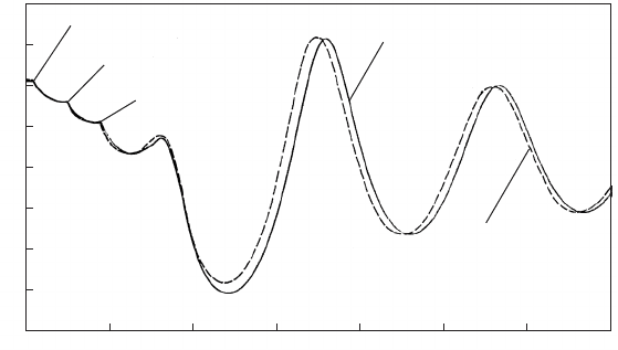
Before embarking on prediction of transient behaviour within the
duplicated system, the opportunity was taken to compare transient
predictions for the original main with field observations. This is very
desirable for all systems but often only possible on larger installations.
Figure 15.6 shows comparisons of transient piezometric level at the
pumping station for a normal auto-sequence shutdown of three duty
pumps.
Simply adding two new vessels to the existing pair was not sufficient
to avoid sub-atmospheric pressures at higher points on the main follow-
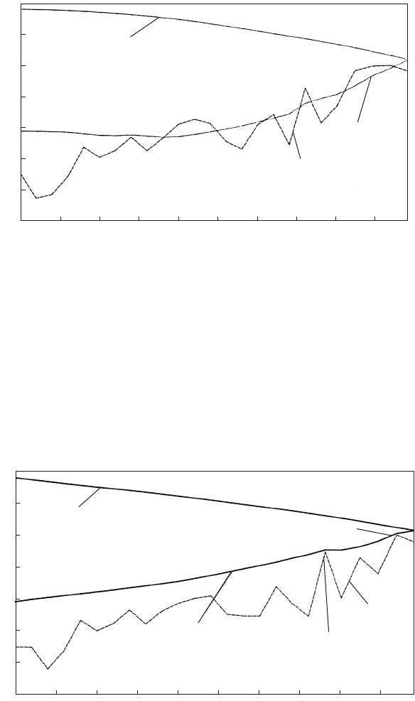
ing a pumping failure. Figure 15.7 depicts the maximum and minimum
transient head along the new main together with the initial profile of
the pipeline.
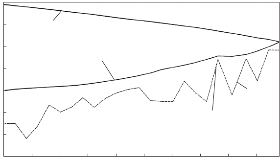
From the initial studies, possible sites for feeder tanks were identified at
high points towards the downstream end of the new main. A number of
feeder arrangements were considered with the option of using feeders at
two different sites being investigated. Since the route had not been fina-
lised, the opportunity was taken to explore alternative possible profiles.
Figure 15.8 shows one such route with two feeder tanks at chainages
14.5 km and 18.2 km. The feeder capacities for this configuration were
268
Trip of 1st pump
2 4 6 8 10 12 14
Time (min.)
Elevation (mAOD)
160
150
140
130
120
110
100
90
Observed head variation
Predicted head variation
Trip of 3rd pump
Trip of 2nd pump
Fig. 15.6. Observed and predicted head at pumping station
Pressure transients in water engineering
quite large and unattractive from an economic standpoint. Using two
tanks was not an attractive option and further adjustments to the
route were made in an attempt to find a more favourable profile.
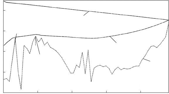
Figure 15.9 shows the final choice with a single small feeder at
chainage 15.2 km.
A dramatic reduction in feeder capacity was achieved through
alteration of the pipeline profile.
269
2 4 6 8 10 12 14 16 18
Chaina
g
e (km)
Elevation (mAOD)
Minimum transient
piezometric level
Pipeline profile
Maximum transient
piezometric level
160
140
120
100
80
60
40
Fig. 15.7. Envelope curve following pump failure without feeder tank
Minimum transient
piezometric level
160
140
120
100
80
60
40
2 4 6 8 10 12 14 16 18
Chaina
g
e
(
km
)
Elevation (mAOD)
Maximum transient
piezometric level
Feeder tank location
Pipeline
profile
Feeder tank
location
Fig. 15.8. Envelope curve following pump failure with possible feeder tanks
Feeder tanks or volumetric tanks
With a feeder tank at chainage 18.2 km the hydraulic gradient
between the tank and the downstream reservoirs was relatively shallow
with only a very gradual flow deceleration occurring. While the feeder is
still supplying water to the downstream pipeline, the vessels start to
refill and this second demand has to be met from the feeder tank, result-
ing in a large capacity chamber.
Altering the route to avoid the summit at chainage 18.2 km allows a
single feeder to be placed at chainage 15.2 km. The transient piezo-
metric gradient between this single tank and the downstream reservoirs
is steeper, allowing a more rapid flow deceleration to develop with flow
reversing in this section of main before the vessels start to refill. The
water for refilling then comes from the downstream reservoirs and
not from the feeder tank. The demand on the feeder thus remains
small, giving a modest feeder capacity.
15.5 Mains duplication: Example 2
A further example of feeder tank behaviour concerns a proposal to
duplicate a raw water pumping main some 17 km in length. The steel
pipelines are 60 in. (1524 mm) in diameter. Profile of the original pipe-
line contains two important summits in the first 4 km from the pumping
station. Pressure vessels at the pumping station would be unrealistically
large to provide complete protection of the pipelines and so two feeder
270
Feeder tank
location
Modified
pipeline
profile
160
140
120
100
80
60
40
2 4 6 8 10 12 14 16 18
Chaina
g
e (km)
Elevation (mAOD)
Maximum transient
piezometric level
Minimum transient
piezometric level
Fig. 15.9. Envelope curves following pump failure with amended profile and
feeder tank
Pressure transients in water engineering
tanks were constructed, one at each summit. Maximum and minimum
transient hydraulic levels are shown in Fig. 15.10 following a pumping
failure with the feeder tanks in operation.
The arrangement of the newer of the two tanks at Ross Loan is shown
in Fig. 15.11. Figure 15.12 shows the main structure of reinforced
concrete under construction, while Fig. 15.13 depicts the branch
from the rising main and the isolating butterfly valve just inside the
valve chamber.
Operation of the feeder tanks was monitored and comparisons made
with predicted behaviour. For the newer tank, Fig. 15.14 shows the
rapid drawdown in water level in this tank after a pumping failure.
This was followed by a gradual recovery of water level controlled by
the throttling action of the filling connection.
The older feeder showed more irregular behaviour with free-surface
wave motion occurring in the tank both at the start of drawdown and
when refilling commenced (Fig. 15.15). These wave actions were
attributed to delayed movement of the non-return valve in the tank
outlet connection.
Detail of feeder tank level at the start of refilling is shown in
Fig. 15.16. It was evident that after the wave motion in the tank sub-
sided, an appreciable rise in water level had taken place. This indicated
that the check valve had not closed promptly after flow reversal but had
stuck in the open position, allowing inflow to the tank through the
outflow connection before the valve eventually closed. Eventual
271
4 8 12 16
Chaina
g
e
(
km
)
Elevation (mAOD)
80
60
40
20
Maximum piezometric level
Minimum piezometric level
Pipeline
profile
Gartinbantrick
feeder
Ross Loan feeder
Fig. 15.10. Envelope curves following pump failure with two feeder tanks
Feeder tanks or volumetric tanks