Ellis,J. Pressure transients in water engineering, A guide to analysis and interpretation of behaviour
Подождите немного. Документ загружается.

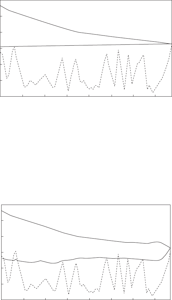
tower provides a storage volume at a level adequate to provide a
continuing gravity flow to downstream consumers when inflow to the
water tower is interrupted. Flow conditions in the upstream pipeline
supplying the tower are improved by lifting the hydraulic gradient to
a higher level. Following a pumping failure, with the towers installed,
minimum transient head conditions are more likely to remain positive
(Fig. 14.18) than without the towers in place (Fig. 14.19). The
252
4 8 12 16 20 24 28
Chaina
g
e (km)
Elevation (mOD)
210
190
170
150
130
110
Fig. 14.18. Envelope curves for pump trip with water towers connected
4 8 12 16 20 24 28
Chaina
g
e (km)
Elevation (mOD)
210
190
170
150
130
110
Fig. 14.19. Envelope curves for pump trip without water towers
Pressure transients in water engineering
elevation of the tower also produces a steeper deceleration gradient
within the upstream pipeline, allowing the water column to come to
rest more quickly. This will assist in limiting the required capacity of
other surge devices such as an air vessel at the pumping station.
14.8.7 Special structures
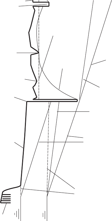
Many outfall systems consist of relatively flat landward sections of
pipeline followed by seaward pipelines which terminate in diffusers.
Consider the example shown in Fig. 14.20. Twin pipelines were of
253
Twin 534 j GRP
landward pipelines
Pumping station
Pipe bridge
Static hydraulic
gradient
Piezometric level
after pump trip
Maximum flow
hydraulic gradien
t
Reduced flow
hydraulic gradient
Air valve
Reduced flow hydraulic
gradient at HWL
Maximum flow
Hydraulic gradient at
HWL,
LWL
Static hydraulic gradient at
HWL,
LWL
Diffuser section
LWL HWL
Twin seaward pipelines
Loop at seawall
Fig. 14.20. Effluent outfall system
Surge tanks and related structures
534 mm diameter thin-walled glass reinforced plastic (GRP). Only quite
small sub-atmospheric pressures were allowable.
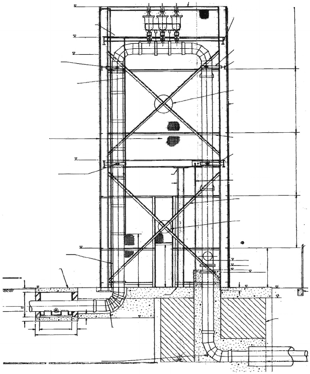
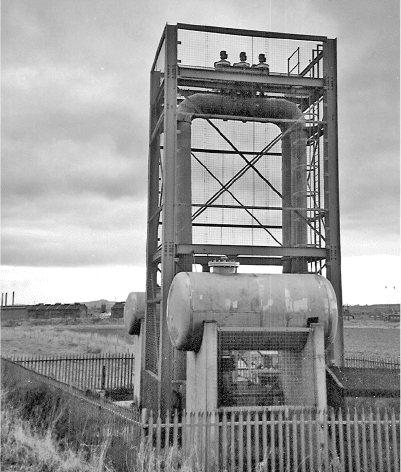
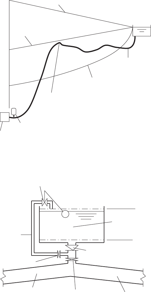
A structure which was specifically constructed to improve transient
conditions is shown in Figs 14.21 and 14.22. This inverted U arrange-
ment was formed to improve minimum transient head conditions along
the effluent pipelines discharging through an outfall beneath a tidal
estuary. At the top of the loop of pipework is a set of three sewage air
valves. The pipeline profile is illustrated in Fig. 14.20. During pumping
at normal maximum flow rate, the upper parts of the loop of pipework at
254
25 thick open mesh galvanised flooring
14.276 m
19.xxx m
i.l. 13.450 m
Detail D
Drg. No. P2325/5/R16
MS galvanised access ladder
with rectangular safety cage
Galvanised 76.2 × 3.25 mm dia
Weldmesh (Ref. no. 310) supported
on angles to within 1829 mm of
base: thereafter mesh is
25.4 × 25.5 × 2.64 mm dia.
(ref. no. 1118)
4.355 m
1.100 m
8.476 m
Detail G
Drg No/ P2325/5/R15
534 mm dia. flange plain ended
GRP pipes 1000 mm long
Scour chamber, floors and
walls lined with G.R.P.
D
2.520 m
Ion
I.L. 1.450
215
215
1500
1930
200
200
2445
2000
1829
1178
200
See detail L
Drg No. P2325/5/R16
305×127 mm×37 kg m
UB (2 No. 5632 mm long)
8 No. 305 × 127mm × 37 kg
1 m UBs
4 No. 5126 mm long
4 No. 5980 mm long
Detail P
Drg No. P2325/5/R16
2 No. 152 × 152 mm × 23 kg
1 m UCs
Detail No. 1
4 No. 365 × 368 mm × 177 kg
1 m UCs
(4 No. 13.362 mm long)
Note Column ends fabricated
flush for bearing
20 No. 150 × 90 mm angles
Detail F
Drg. No. P2325/5/R15
Inner tie 25 dia.
Detail K Drg No.
P2325/5/R15
See detail J
Drg No. P2325/5/R15
2 No. 534 m dia. G.R.P. pipes
concreted in to base and
upstand
16 No. 60 × 60 mm angles
(angles back to back)
Detail No. 1
I.L. 3.720 m
3.500 m
2.300 m
3.200 m
GL. 2.50 m
2.026
Blass infill
2.526
200
2432 2971 2971 2971
Fig. 14.21. Inverted U pipework arrangement with air valves
Pressure transients in water engineering
the seawall are primed with the air valves shut. Hydraulic gradient over
the air valves is sufficient to keep the valves tight shut. At lesser flow
rates the air valves will be open and the top of the loop represents
the downstream limit of the pumping mains. At low flows and/or low
tide level, the seaward section of the system flows under gravity. This
arrangement has the merits of providing an almost constant static
head against which pumps can operate. As far as pressure transient
behaviour is concerned, the loop of pipework creates a useful adverse
hydraulic gradient along the landward stretch of pipeline, which
produces a more rapid flow deceleration along this part of the system.
Sub-atmospheric pressures are thus minimised and quantities of air
admitted through operation of air valves along the landward stretches
of pipeline are reduced. Demands on pressure vessels located at the
pumping station are also more modest, allowing smaller vessels to be
installed. Without the inverted U of pipework at the seawall, large sec-
tions of the landward pipelines would deprime after a pumping failure,
more substantial vacuum pressures would occur and the size of pressure
vessels would have to be greatly increased. The resulting process of
restarting pumps would involve removal of large volumes of air from
the system before a steady pumping regime could be established.
255
Fig. 14.22. Inverted U showing air valves and vessels
Surge tanks and related structures
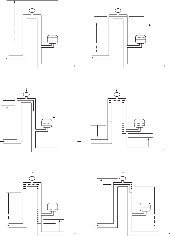
Modelling hydraulic conditions at the loop of pipework requires
consideration of a number of regimes, just some of which are depicted
in Fig. 14.23. After each time increment of a simulation the following
variables must be established.
256
––
–
M
M
M
M
M
H
u/s
H
u/s
H
u/s
H
u/s
H
u/s
H
d/s
Z
u/s
M
Z
u/s
M
Z
u/s
M
Z
d/s
M
Z
d/s
M
Z
d/s
V
u/s
V
d/s
H
d/s
H
d/s
H
d/s
H
d/s
V
u/s
V
u/s
V
d/s
V
d/s
V
d/s
V
d/s
V
d/s
V
u/s
V
u/s
H
u/s
= H
d/s
V
u/s
(
e
)(
f
)
(c) (d)
(a) (b)
Air outflowAir outflow
Air inflow
Air inflow
Air inflow
Air valve
(closed)
Piezometric level
Pressure
vessel
Fig. 14.23. Sequence of operation of inverted U arrangement
Pressure transients in water engineering
Upstream and downstream piezometric level H
u=s
and H
d=s
;
upstream and downstream velocity V
u=s
and V
d=s
;
upstream and downstream water level Z
u=s
and Z
d=s
;
air inflow/outflow rate through air valves Q
air
; and
gauge pressure head within the air mass h.
Equations available are as follows.
The quasi-invariant relationships from upstream and downstream
characteristics:
V
u=s
þ g=aH
u=s
¼ Cþ and V
d=s
þ g=aH
d=s
Air flow relationship for the air valves:
Q
air
¼function ðhÞ
fobtained from valve supplier, inflow assumed þ veg
Conservation of volume within the air mass:
ðV
d=s
V
u=s
ÞA Q
air
¼ dðVolÞ=dt
V
u=s
A ¼ dZ
u=s
=dt and V
d=s
A ¼dZ
d=s
=dt
Polytropic relationship for the air mass:
ðh þ h
atm
ÞVol
n
¼ constant fover a time stepg
Also
H
u=s
Z
u=s
¼ h ¼ H
d=s
Z
d=s
Not all of these equations are applicable for each flow regime of
Fig. 14.23.
(a) During steady pumping at maximum design rate and with higher
tide levels the loop is fully primed with piezometric level above the
operating level of air valves. Air volume in the downstream pressure
vessel is compressed to its minimum at this stage. V
u=s
¼ V
d=s
,
H
u=s
¼ H
d=s
, Q
air
¼ 0:0andVol ¼ 0:0 at this time. Solution is
achieved using the quasi-invariant relationships alone.
(b) After pumping failure, piezometric level at the loop falls and air
valves open. Air inflow commences and an air pocket develops at
the top of the loop. While the air—effluent interface lies above
pipe invert level at the top of the loop then H
u=s
¼ H
d=s
,
V
u=s
< V
d=s
and h is ve. Air mass in the pressure vessel starts to
expand.
257
Surge tanks and related structures
(c) Air inflow continues and effluent flows over the top of the loop
cascading into the downstream vertical pipe with level falling in
this part of the loop. Air charge within the pressure vessel continues
to expand. H
u=s
< H
d=s
, Z
d=s
< Z
u=s
, V
u=s
< V
d=s
, Q
air
is þve and h
is ve.
(d) Effluent level in the downstream vertical section falls below the
vessel connection and the air masses are united. Upstream flow
will finally reverse as effluent moves upstream attempting to refill
the vessel at the pumping station and removing air admitted to
the pipeline through upstream air valves. The effluent level falls
in the vertical upstream leg of the loop. Eventually upstream and
downstream effluent levels are stabilised with the seaward level
equal to the prevailing tide level. Pressure of the air mass becomes
atmospheric.
(e) When pumps are restarted effluent level in the upstream leg rises
and pressure in the air mass h
is
þ ve. The increase in pressure
starts to push air out of the air valves on top of the loop and
volume of the air mass starts to decrease. Increased pressure
causes a small positive velocity to develop in the downstream
pipeline.
(f ) With continued pumping the upstream leg is filled and flow
cascades into the downstream pipe producing a level increase and
isolating the vessel. Under the action of rising downsteam level,
flow develops in the seaward section of pipelines. If flow is below
the maximum or if tide level is low, the loop may remain only
partially primed. When an equilibrium condition is achieved and
V
u=s
¼ V
d=s
, air venting ceases with the remaining air mass being
at atmospheric pressure h ¼ 0 :0.
258
Pressure transients in water engineering
15
Feeder tanks or volumetric
tanks
Some pipeline profiles are ‘unfavourable’ with respect to avoiding
negative pressures (Fig. 15.1). In the case of a treated water main it
would not be acceptable to permit minimum pressures to fall to a
point where negative pressures developed in the pipeline. Providing a
pressure vessel arrangement of sufficient capacity to alleviate unaccep-
table minimum pressures to an adequate extent throughout the system
may not be a practical proposition because of the very large vessel
capacity required.
It is a general principle that the requirement for pressure transient
protection can be most efficiently met by installing the equipment as
close as possible to the area affected. Additional protection can be
installed at an intermediate summit or a high point on the pipeline.
For a treated water pipeline an additional pressure vessel might be
installed at the summit. Alternatively this local protection may take
the form of a surge tank. If the height of a surge chamber was imprac-
tical or visually unacceptable then a feeder or volumetric tank can be
used. Like a pressure vessel, a feeder tank acts as an alternative
source of water following a pumping failure. By supplying water to a
downstream pipeline, rates of deceleration are reduced and with
these corresponding pressure changes.
15.1 Components and location of a feeder tank
The primary elements making up a feeder tank are illustrated in Fig. 15.2.
Being open to the atmosphere a feeder tank will behave in some
respects as a surge tank. The main difference is that the feeder is
isolated from the pipeline under steady flow and only comes into
operation during a transient event when piezometric level falls below
259
260
Minimum hydraulic gradient following
a pumping failure and with pressure
vessel at PS for protection
Pipeline profile
Minimum piezometric level following a
pumping failure and without protection
Possible location
of feeder tank
Pressure vessel
Pumpin
g
station
Steady pumping hydraulic gradient
Service
reservoir
M
Fig. 15.1. Pipeline showing possible feeder tank location
Float-operated valve
Filling
connection
Feeder tank
TWL
BWL
Non-return valve (NRV)
outflow only
Isolating valve
Upstream pipeline
Isolating valve
Downstream pipeline
Fig. 15.2. Schematic of feeder tank showing principal features
Pressure transients in water engineering
the water level in this tank. Feeder tanks will usually be located at a
high point on the main where preliminary analysis without local protec-
tion has shown transient sub-atmospheric pressures to occur.
To limit maximum water level in the feeder tank a non-return valve
(NRV) is positioned in the outlet connection. This NRV shuts as flow
attempts to re-enter the tank, forcing flow through the relatively
modest filling connection. As water level in the tank rises, an inlet
valve, often a float valve, progressively closes, shutting off inflow as
level approaches TWL. The filling connection is sized so as to restrict
inflow rates to ensure that no secondary surging of any significance is
generated during filling. Capacity of the feeder tank should be arranged
so that no air is able to enter the pipeline.
15.2 Mode of operation
Assuming the feeder tank to be filled at the outset, then supposing a
pumping failure occurs at a pumping station towards the upstream
end of the main. A fall in pressure or downsurge, will travel downstream
from the pumping station. The decreasing piezometric level is accom-
panied by a reducing upstream velocity and deceleration dV= dt .
While the declining piezometric level remains above the water level
within the feeder tank, the NRV will remain closed and the tank will
have no influence on the passage of the transient along the pipeline.
Deceleration dV=dt will be the same downstream of the tank connec-
tion as in the upstream main.
It is advisable when developing a piece of software to consider abnor-
mal circumstances and to ensure that the modelling process can cater
for all eventualities. In the present context this would include, among
other scenarios, prediction of tank emptying and development of an
air pocket in the pipeline (Fig. 15.3b—e). Such abnormal behaviour
has been observed and will be discussed later in this chapter. A brief
description of some of these configurations is given below.
(a) Only when piezometric level in the main at the tank connection
has fallen below the prevailing water level in the tank, does the
NRV open to allow outflow from the tank into the pipeline. At
this stage:
V
u=s
A
u=s
þ Q ¼ V
d=s
A
d=s
ð15:1Þ
that is, the downstream flow is augmented by outflow from the tank
thus reducing the rate of deceleration of flow in the downstream
pipeline below that in the upstream part of the main — that is
261
Feeder tanks or volumetric tanks