Ellis,J. Pressure transients in water engineering, A guide to analysis and interpretation of behaviour
Подождите немного. Документ загружается.

below the prevailing water level in reservoir No. 1 then a check valve on
the bypass line will open to permit flow from reservoir No. 1 into the
rising mains thus augmenting flow from the vessels and inhibiting
further substantial head drop in the mains. The bypass line is some
60 m in length and overall losses in this line should be taken into
account in any simulation.
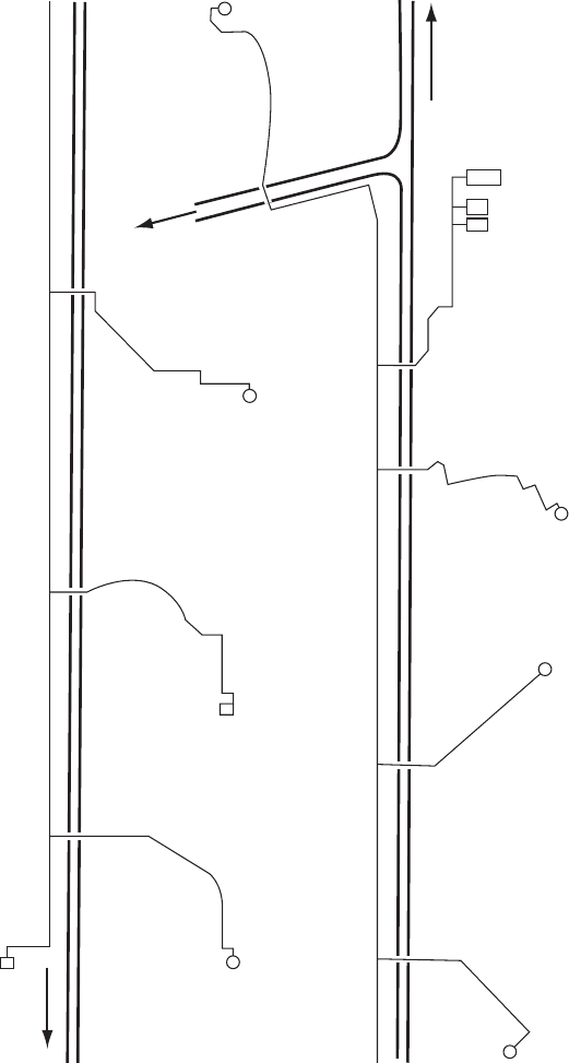
14.8.2 Operation of an existing service reservoir
The City of Harare water supply system contains a large number of
service reservoirs (SRs) supplied via five large trunk mains. These
mains are filled by pumping treated water from Warren Park Pumping
Station (Fig. 14.8). When pumps are idle, reticulation flows can
occur from some of these reservoirs which are thus equipped to allow
both inflow and outflow. To protect the ring mains following a pumping
failure at Warren Park, involving simultaneous failure of 12 duty
pumps, a set of pressure vessels was recommended with a gross
volume of 550 m
3
. During the downsurge following trip of pumps,
head in rising main No. 1 falls below the water level in the nearby
242
750 mm
975 mm
800 mm
300 mm
375 mm
1000 mm
1500 mm
Warren Park PS
450 mm
Viking SR comple
x
Fig. 14.8. Service reservoirs as surge chambers
Pressure transients in water engineering
Viking SR, causing outflow from this storage facility. This outflow pro-
vides a source of water for surge suppression in addition to that from the
pressure vessels. The vessels’ volume could be reduced by 50 m
3
were
Viking SR relied upon to yield water after all pump trip events.
Use of service reservoirs in this way depends upon the existence of a
backflow connection. Otherwise, instead of outflow from the reservoir,
air valves may open allowing the line to deprime. If there are no air
valves, high vacuum pressures may occur in the branch serving the
reservoir. Even if it is not the intention to utilise an SR for surge
duties in this way, hydraulic transients are such that the reservoir
branch will be affected and should therefore be included in any
modelling exercise. If it is not the intention to allow reversed flow
from the SR and it is necessary to avoid vacuum pressures then a
check valve can be included on the branch main close to its connection
to the trunk main.
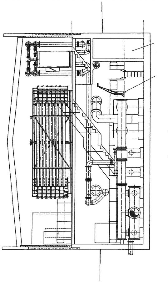
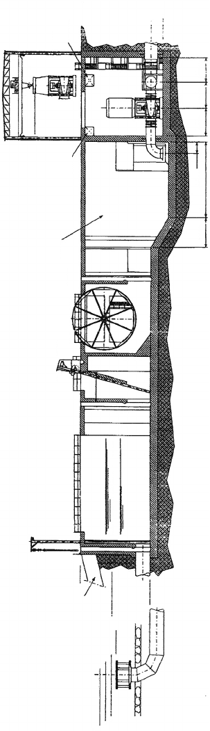
14.8.3 Filtration plant
First consider the Three Valleys Water North Mymms Ultrafiltration
membrane plant shown in Fig. 14.9. This installation removes particles
down to the macromolecular level with a relatively modest head drop
through the membranes themselves. At a design flow rate of
1590 m
3
/h, eight membrane units will be in service at any time, with
a further unit possibly undergoing programmed maintenance.
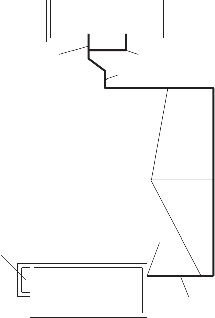
This system obtains water from a feed tank just upstream of the plant
building itself and delivers treated permeate to a contact tank a
relatively short distance outside the plant (Fig. 14.10). Since water
levels in the feed and contact tanks vary only by a maximum of
200 mm, the static head is very small in comparison with head losses
associated with system components.
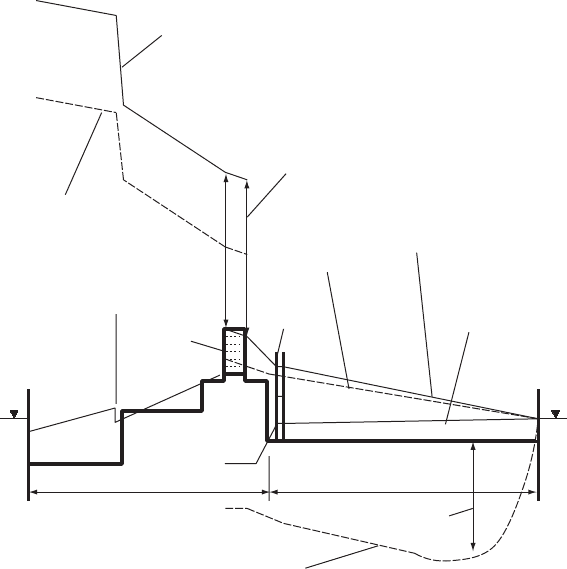
The membrane units of Fig. 14.9 are at a height of around 3 m above
the normal water level in the feed tank which is at 78.5 mAOD. The
absence of any effective static lift means that parts of the membrane
plant are subject to vacuum pressures both under steady flow and
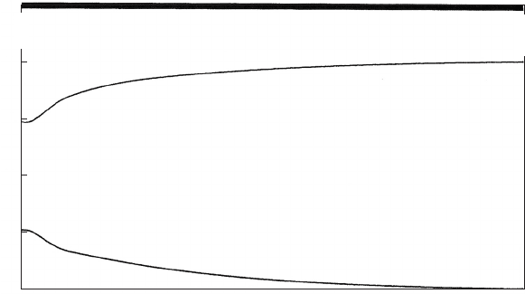
also static conditions. Figure 14.11 shows a section through the pipeline
system together with the static and steady flow gradients.
To ensure that there is no risk to water quality in the underground
pipeline from the membrane plant to the contact tank, positive
pressures should be maintained along this stretch following pumping
failure. Figure 14.11 also shows maximum and minimum hydraulic
gradients after trip of two duty pumps. Vacuum pressures were predicted
243
Surge tanks and related structures
244
EL +81.0
M
EL +75.50
M
GL +78.80
M
Dirty backwash
holding tank 40 m
3
Lifting davit
Primary
strainers
Primary units
Section A–A
Backwash pumpsFeed pumps
CIP
f600
f600
f700
Secondary
units
GL +78.70
M
Fig. 14.9. Membrane units
Pressure transients in water engineering
along the downstream pipeline. A small chamber, surface area 3.14 m
2
,
was installed on the downstream side of the membrane plant to alleviate
transient conditions along this pipeline after pumping failure. By
reducing the rate of flow deceleration dV=dt in the pipeline, þve
pressures were maintained (Fig. 14.11). Peak water levels in the tank
were also determined during pump startup to ensure that adequate
freeboard was provided.
14.8.4 Seawater intake system
A second example concerns the seawater intake system shown in Fig.
14.12. Twin 2 m diameter pipelines of average length 226 m lead
from intakes to inlet chambers of a pumping station. Each inlet pipe
245
UF membrane plant
Contact tank
WL = 78.5 mAOD
Feed tank
WL = 78.5 mAOD
DN 600
DN 450
DN 500
DN 600
Permeate line to
contact tanks
Location of surge tank
Fig. 14.10. Membrane plant layout
Surge tanks and related structures
supplies two pumps from a single stilling chamber. A maximum of three
pumps will operate at any time — that is, two pumps drawing from one
intake and the third pump from the second intake. The water level in a
stilling chamber is a function of the prevailing sea level and the number
of pumps operating. Maximum level will occur if two pumps drawing
from the same intake are tripped together when sea level is at its max-
imum. Minimum level will be established when two pumps are started
in the same stilling chamber with minimum sea level.
Since change of water level in the chamber is small during one
time step it is reasonable to calculate conditions of flow through
pumps using a suction water level held constant at the initial level
for that increment. Thus flow rate Q through pumps can be found
and averaged over the increment. The equation for conservation of
volume gives:
AðV þ V
o
Þ=2 ðQ þ Q
o
Þ=2 ¼ A
t
dH=dt ð14:12Þ
246
Within membrane plant building Underground pipeline
Steady pumping – 2 pumps
Piezometric line – max. resistance
Head drop through membrane unit
Feed tank
WL 78.5
Contact tan
k
WL 78.5
Surge tank
Primary strainers
Min. piezometric level
with surge tank
Steady flow – max. resistance
min. resistance
Membrane
units
Steady pumping
Piezometric line –
min. resistance
Min.
p
iezometric level without
p
rotection
Sub-atmospheric head
Fig. 14.11. Head changes through membrane plant
Pressure transients in water engineering
247
Seawater
intake
Stop
gate
Stop
gate
Stop
gate
Overflow
weir
Forebay chamber
–6.50
–4.00
Inlet
pipes
–0.70
5158
+2.04 HWL
+1.04 MWL
+0.04 LWL
MSL = 0.00
+5.50
Trash rack
Max. tidal water = +1.13
Min. tidal water = –1.40
Drum screen
Stilling
chamber
Pipes
reserve
Cables
reserve
Cooling
water
pumps
2000
Crane
30 T
+13.50
5200
–9.50
–6.50
–8.5
13004 4800 4500 4200
Fig. 14.12. Seawater intake system
Surge tanks and related structures
and the Cþ characteristic yields:
V þ g=aH ¼ Jþ
Unknowns V and H can be easily found.
As an illustration consider the case where three pumps are operating
and that a single pump using one of the stilling chambers is tripped. The
remaining two pumps operating together with the second stilling cham-
ber continue to function. Figure 14.13 shows the predicted changes in
water level in the two stilling chambers. Water level in the chamber of
the pump which has been tripped increases towards the prevailing sea
level while water level in the other chamber falls to a lower level as
the operating pumps deliver increased flow. This increased flow
comes about as a consequence of falling head in the common down-
stream discharge header after the pump failure.
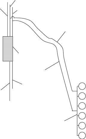
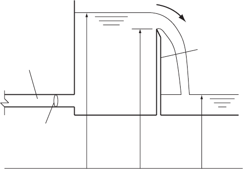
14.8.5 Seal weir
At the downstream extremity of a cooling water circuit, the pipeline
system is often maintained at a predetermined head by providing a
seal weir (Fig. 14.14).
When tank head H > Z
w
flow over the weir is given by:
Q ¼ C
d
B
p
ð2g Þð H Z
w
Þ
3=2
ð14:13Þ
and when H Z
w
then:
Q ¼ 0:0
248
Time
(
s
)
Level (mASL)
0
–0.5
–1.0
–1.5
–2.0
–2.5
0.048
6.166
12.285
18.403
24.521
30.640
36.758
42.876
48.994
55.113
61.231
67.349
73.467
79.585
85.703
91.822
97.940
104.058
110.176
116.294
122.412
128.531
134.650
140.769
146.888
153.007
159.126
165.245
171.365
177.484
183.603
189.722
Fig. 14.13. Head variations at seawa ter intake chambers
Pressure transients in water engineering
Variations of coefficient of discharge C
d
for the weir can be found
from the literature for different weir forms and tabulated as a function
of head over the crest H Z
w
for interpolation during computations.
The initial value of crest head H
o
Z
w
is usually adequate to give a
value of C
d
for each time increment.
For conservation of volume in the tank:
AðV þ V
o
Þ=2 ðQ
w
þ Q
wo
Þ=2 ¼ A
t
dH=dt
and
dH=dt ¼ðH H
o
Þ=t
and from the Cþ characteristic:
V þ g=aH ¼ Jþ
The equations can be easily solved for V and H.
Figure 14.15 shows a typical example of changing tank level after trip
of three operating pumps.
14.8.6 Water towers
Other structures may be specifically constructed either to improve
normal operational behaviour but with some benefits to transient
conditions, or may be created specifically for the purpose of alleviating
transient conditions.
249
Common horizontal datum
Cross-section = A
H
Inlet pipeline
Z
w
Q
w
Seal weir
Tailwater
Fig. 14.14. Seal weir arrangement
Surge tanks and related structures
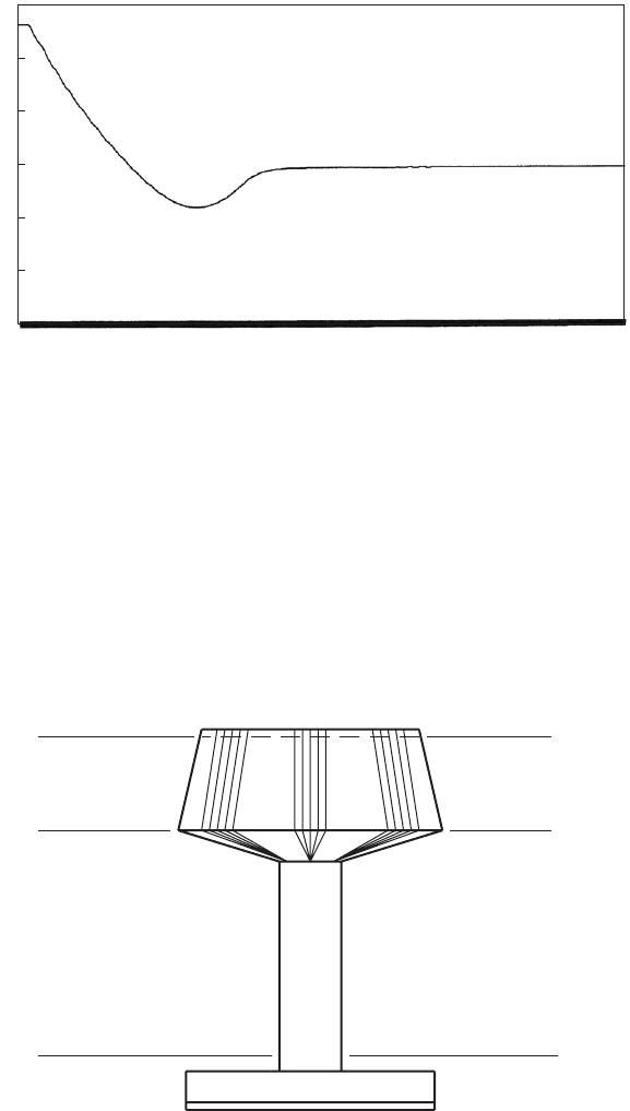
An example of a structure which improves normal operational
behaviour is a water tower (Fig. 14.16). A structure such as this
would be constructed in an area where topography does not provide a
sufficiently elevated site for a local ground storage tank. The plan
arrangement of a number of such towers is shown in Fig. 14.17. The
250
0.048
6.166
12.285
18.403
24.521
30.640
36.758
42.876
48.994
55.113
61.231
67.349
73.467
79.585
85.703
91.822
97.940
104.058
110.176
116.294
122.412
128.531
134.650
140.769
146.888
153.007
159.126
165.245
171.365
177.484
183.603
189.722
Time (s)
Level (mASL)
5.4
5.3
5.2
5.1
5.0
4.9
4.8
Fig. 14.15. Head variation upstream of seal weir following pumping failure
153.700 mASL
171.650 mASL
175.000 mASL
GL
BWL
TWL
M
M
M
Geassa elevated tank (water tower),
Eastern Liwa, Abu Dhabi, UAE
Fig. 14.16. Typical water tower
Pressure transients in water engineering
251
To Hameem
Nashash ELT
Hawatheen ELT
ND 150 DI
ND 150 DI
ND 150 DI
ND 400 DI
ND 400 DI
ND 400 DI
ND 400 DI
ND 150 DI
ND 150 DI
ND 150 DI
ND 400 DI
ND 400
ND 400
ND 150
ND 150
Shah ELT
BPT
Tharwaniya GT
Gurmeda ELT
Sabkha ELT
To Nafeer
Al Raiqa ELT
Mizaira’a
Mizaira’a PS
Chlorination
Surge protection
Fig. 14.17. Pipeline system serving water towers and ground tanks
Surge tanks and related structures