Fitzgerald A.E. Electric Machinery
Подождите немного. Документ загружается.

366 CHAPTER 7 DC Machines
the circular arcs. The end connections at the back of the armature are shown dashed
for the two coils in slots 1 and 7, and the connections of these coils to adjacent
commutator segments are shown by the heavy arcs. All coils are identical. The back
end connections of the other coils have been omitted to avoid complicating the figure,
but they can easily be traced by remembering that each coil has one side in the top of
a slot and the other side in the bottom of the diametrically-opposite slot.
In Fig. 7.7a the brushes are in contact with commutator segments 1 and 7. Current
entering the fight-hand brush divides equally between two parallel paths through the
winding. The first path leads to the inner coil side in slot 1 and finally ends at the brush
on segment 7. The second path leads to the outer coil side in slot 6 and also finally ends
at the brush on segment 7. The current directions in Fig. 7.7a can readily be verified
by tracing these two paths. They are the same as in Fig. 4.22. The effect is identical
to that of a coil wrapped around the armature with its magnetic axis vertical, and a
clockwise magnetic torque is exerted on the armature, tending to align its magnetic
field with that of the field winding.
Now suppose the machine is acting as a generator driven in the counterclockwise
direction by an applied mechanical torque. Figure 7.7b shows the situation after the
armature has rotated through the angle subtended by half a commutator segment. The
right-hand brush is now in contact with both segments 1 and 2, and the left-hand
brush is in contact with both segments 7 and 8. The coils in slots 1 and 7 are now
short-circuited by the brushes. The currents in the other coils are shown by the dots
and crosses, and they produce a magnetic field whose axis again is vertical.
After further rotation, the brushes will be in contact with segments 2 and 8, and
slots 1 and 7 will have rotated into the positions which were previously occupied by
slots 12 and 6 in Fig. 7.7a. The current directions will be similar to those of Fig. 7.7a
except that the currents in the coils in slots 1 and 7 will have reversed. The magnetic
axis of the armature is still vertical.
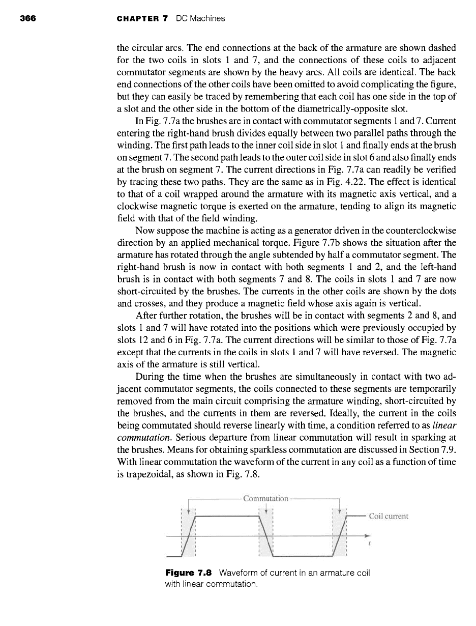
During the time when the brushes are simultaneously in contact with two ad-
jacent commutator segments, the coils connected to these segments are temporarily
removed from the main circuit comprising the armature winding, short-circuited by
the brushes, and the currents in them are reversed. Ideally, the current in the coils
being commutated should reverse linearly with time, a condition referred to as
linear
commutation.
Serious departure from linear commutation will result in sparking at
the brushes. Means for obtaining sparkless commutation are discussed in Section 7.9.
With linear commutation the waveform of the current in any coil as a function of time
is trapezoidal, as shown in Fig. 7.8.
Commutation
,~,
l
i |
Coil current
Figure
7.8 Waveform of current in an armature coil
with linear commutation.
7.3 Effect of Armature MMF 367
The winding of Fig. 7.7 is simpler than that used in most dc machines. Ordi-
narily more slots and commutator segments would be used, and except in small ma-
chines, more than two poles are common. Nevertheless, the simple winding of Fig. 7.7
includes the essential features of more complicated windings.
7.3 EFFECT OF ARMATURE MMF
Armature mmf has definite effects on both the space distribution of the air-gap flux
and the magnitude of the net flux per pole. The effect on flux distribution is important
because the limits of successful commutation are directly influenced; the effect on
flux magnitude is important because both the generated voltage and the torque per
unit of armature current are influenced thereby. These effects and the problems arising
from them are described in this section.
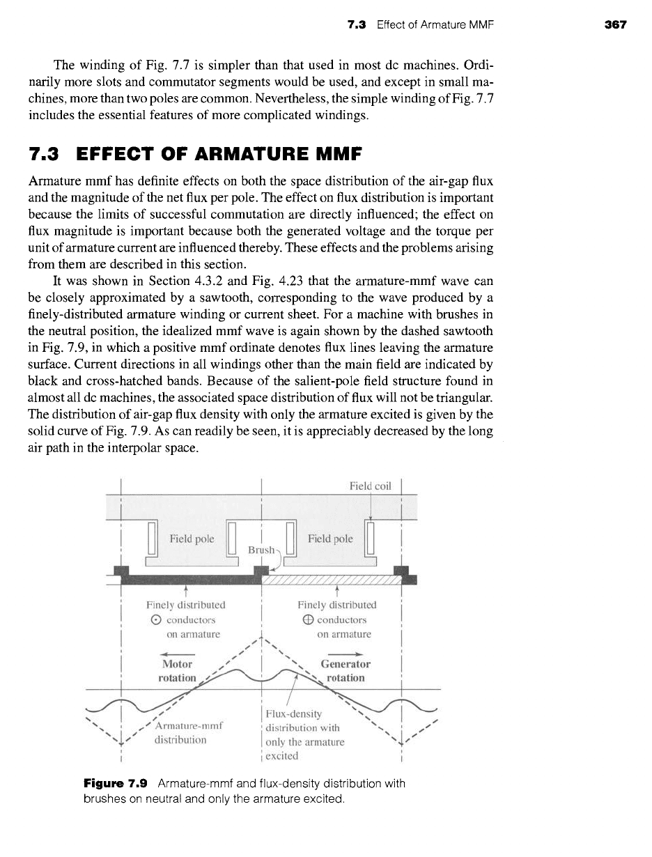
It was shown in Section 4.3.2 and Fig. 4.23 that the armature-mmf wave can
be closely approximated by a sawtooth, corresponding to the wave produced by a
finely-distributed armature winding or current sheet. For a machine with brushes in
the neutral position, the idealized mmf wave is again shown by the dashed sawtooth
in Fig. 7.9, in which a positive mmf ordinate denotes flux lines leaving the armature
surface. Current directions in all windings other than the main field are indicated by
black and cross-hatched bands. Because of the salient-pole field structure found in
almost all dc machines, the associated space distribution of flux will not be triangular.
The distribution of air-gap flux density with only the armature excited is given by the
solid curve of Fig. 7.9. As can readily be seen, it is appreciably decreased by the long
air path in the interpolar space.
%%%%%
i
I
II
Field coi
Finely distributed ' Finely distributed
I~) conductors (~ conductors
on armature on armature
S'
'%
S %
Motor
s S
rota~
S
s S
Armature-mmf
S
," distribution
%
",,
Generator
~~'~~ation
Flux-density "" ~ ~~"'~'~
% s
' distribution with
",, ' s S
% s
only the armature ",, s
'excited
Figure 7.9 Armature-mmf and flux-density distribution with
brushes on neutral and only the armature excited.
368 CHAPTER 7 DC Machines
Field iron
Armature
iron
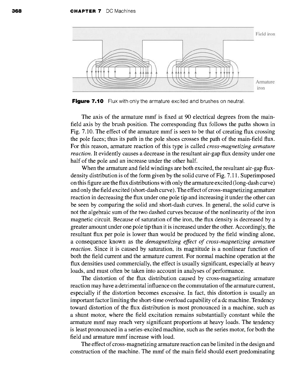
Figure
7.10 Flux with only the armature excited and brushes on neutral.
The axis of the armature mmf is fixed at 90 electrical degrees from the main-
field axis by the brush position. The corresponding flux follows the paths shown in
Fig. 7.10. The effect of the armature mmf is seen to be that of creating flux crossing
the pole faces; thus its path in the pole shoes crosses the path of the main-field flux.
For this reason, armature reaction of this type is called
cross-magnetizing armature
reaction.
It evidently causes a decrease in the resultant air-gap flux density under one
half of the pole and an increase under the other half.
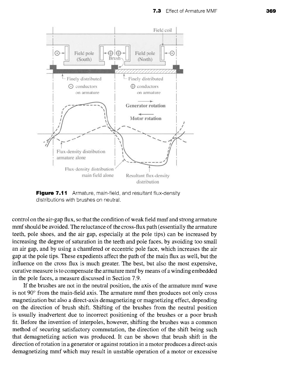
When the armature and field windings are both excited, the resultant air-gap flux-
density distribution is of the form given by the solid curve of Fig. 7.11. Superimposed
on this figure are the flux distributions with only the armature excited (long-dash curve)
and only the field excited (short-dash curve). The effect of cross-magnetizing armature
reaction in decreasing the flux under one pole tip and increasing it under the other can
be seen by comparing the solid and short-dash curves. In general, the solid curve is
not the algebraic sum of the two dashed curves because of the nonlinearity of the iron
magnetic circuit. Because of saturation of the iron, the flux density is decreased by a
greater amount under one pole tip than it is increased under the other. Accordingly, the
resultant flux per pole is lower than would be produced by the field winding alone,
a consequence known as the
demagnetizing effect of cross-magnetizing armature
reaction.
Since it is caused by saturation, its magnitude is a nonlinear function of
both the field current and the armature current. For normal machine operation at the
flux densities used commercially, the effect is usually significant, especially at heavy
loads, and must often be taken into account in analyses of performance.
The distortion of the flux distribution caused by cross-magnetizing armature
reaction may have a detrimental influence on the commutation of the armature current,
especially if the distortion becomes excessive. In fact, this distortion is usually an
important factor limiting the short-time overload capability of a dc machine. Tendency
toward distortion of the flux distribution is most pronounced in a machine, such as
a shunt motor, where the field excitation remains substantially constant while the
armature mmf may reach very significant proportions at heavy loads. The tendency
is least pronounced in a series-excited machine, such as the series motor, for both the
field and armature mmf increase with load.
The effect of cross-magnetizing armature reaction can be limited in the design and
construction of the machine. The mmf of the main field should exert predominating
7.3 Effect of Armature MMF 369
llll~;lff UlbLIIt)UL~U l'llll;lJ UI~tlIUUL~U i,
I
(~) conductors ~) conductors
on armature on armature '
i i Go.or.torr t.t,o°
i/f t, ki
Motor rotation
, I , , I
I Flux-density distribution I ll\ ;/
I
,
armature alone
, i ~.
ff I
i i
Flux-density distribution " g
main field alone Resultant flux-density
distribution
Figure
7.11 Armature, main-field, and resultant flux-density
distributions with brushes on neutral.
control on the air-gap flux, so that the condition of weak field mmf and strong armature
mmf should be avoided. The reluctance of the cross-flux path (essentially the armature
teeth, pole shoes, and the air gap, especially at the pole tips) can be increased by
increasing the degree of saturation in the teeth and pole faces, by avoiding too small
an air gap, and by using a chamfered or eccentric pole face, which increases the air
gap at the pole tips. These expedients affect the path of the main flux as well, but the
influence on the cross flux is much greater. The best, but also the most expensive,
curative measure is to compensate the armature mmfby means of a winding embedded
in the pole faces, a measure discussed in Section 7.9.
If the brushes are not in the neutral position, the axis of the armature mmf wave
is not 90 ° from the main-field axis. The armature mmf then produces not only cross
magnetization but also a direct-axis demagnetizing or magnetizing effect, depending
on the direction of brush shift. Shifting of the brushes from the neutral position
is usually inadvertent due to incorrect positioning of the brushes or a poor brush
fit. Before the invention of interpoles, however, shifting the brushes was a common
method of securing satisfactory commutation, the direction of the shift being such
that demagnetizing action was produced. It can be shown that brush shift in the
direction of rotation in a generator or against rotation in a motor produces a direct-axis
demagnetizing mmf which may result in unstable operation of a motor or excessive
370 CHAPTER 7 DC Machines
drop in voltage of a generator. Incorrectly placed brushes can be detected by a load
test. If the brushes are on neutral, the terminal voltage of a generator or the speed of
a motor should be the same for identical conditions of field excitation and armature
current when the direction of rotation is reversed.
7.4 ANALYTICAL FUNDAMENTALS:
ELECTRIC-CIRCUIT ASPECTS
From Eqs. 7.1 and 7.4, the electromagnetic torque and generated voltage of a dc
machine are, respectively,
and
where
Tmech --
Ka~dla
(7.13)
Ea = Ka ~dCOm (7.14)
poles
C a
Ka = (7.15)
2n'm
Here the capital-letter symbols Ea for generated voltage and Ia for armature
current are used to emphasize that we are primarily concerned with steady-state
considerations in this chapter. The remaining symbols are as defined in Section 7.1.
Equations 7.13 through 7.15 are basic equations for analysis of the machine. The
quantity
Eala
is frequently referred to as the
electromagnetic power;
from Eqs. 7.13
and 7.14 it is related to electromagnetic torque by
Eala
Tmech = -- Ka~dla (7.16)
O)m
The electromagnetic power differs from the mechanical power at the machine
shaft by the rotational losses and differs from the electric power at the machine
terminals by the shunt-field and armature 12 R losses. Once the electromagnetic power
Eala
has been determined, numerical addition of the rotational losses for generators
and subtraction for motors yields the mechanical power at the shaft.
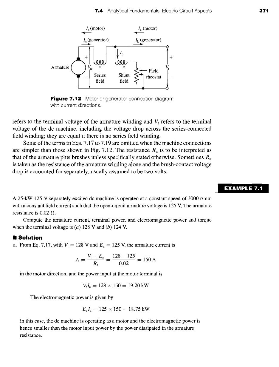
The interrelations between voltage and current are immediately evident from the
connection diagram of Fig. 7.12. Thus,
and
Va -- E a -at- l a R a
Vt -- Ea -4-/a(Ra -k- Rs)
(7.17)
(7.18)
IL
=
la q'- If (7.19)
where the plus sign is used for a motor and the minus sign for a generator and Ra and Rs
are the resistances of the armature and series field, respectively. Here, the voltage Va
7.4 Analytical Fundamentals: Electric-Circuit Aspects 371
I a (motor)
I a (generator)
Armature i a Se!ieSfield
/L
(motor)
I L (generator)
T
r e elsaatl i'-
Figure 7.12
Motor or generator connection diagram
with current directions.
refers to the terminal voltage of the armature winding and Vt refers to the terminal
voltage of the dc machine, including the voltage drop across the series-connected
field winding; they are equal if there is no series field winding.
Some of the terms in Eqs. 7.17 to 7.19 are omitted when the machine connections
are simpler than those shown in Fig. 7.12. The resistance Ra is to be interpreted as
that of the armature plus brushes unless specifically stated otherwise. Sometimes Ra
is taken as the resistance of the armature winding alone and the brush-contact voltage
drop is accounted for separately, usually assumed to be two volts.
A 25-kW 125-V separately-excited dc machine is operated at a constant speed of 3000 r/min
with a constant field current such that the open-circuit armature voltage is 125 V. The armature
resistance is 0.02 f2.
Compute the armature current, terminal power, and electromagnetic power and torque
when the terminal voltage is (a) 128 V and (b) 124 V.
II Solution
a. From Eq. 7.17, with Vt = 128 V and Ea = 125 V, the armature current is
Vt- Ea 128- 125
Ia -- = = 150A
Ra 0.02
in the motor direction, and the power input at the motor terminal is
Vtla = 128 × 150 = 19.20 kW
The electromagnetic power is given by
Eala =
125 x 150 = 18.75 kW
In this case, the dc machine is operating as a motor and the electromagnetic power is
hence smaller than the motor input power by the power dissipated in the armature
resistance.
EXAMPLE 7.1
372
CHAPTER 7
DC Machines
Finally, the electromagnetic torque is given by Eq. 7.16:
EaIa
18.75 × 10³
Tmech = -- ~-
59.7 N. m
O) m
100zr
b. In this case,
Ea
is larger than Vt and hence armature current will flow out of the machine,
and thus the machine is operating as a generator. Hence
and the terminal power is
The electromagnetic power is
Ea- Vt 125- 124
Ia = = =50A
Ra 0.02
Vt la = 124 × 50 = 6.20 kW
Eala
= 125 x 50 = 6.25 kW
and the electromagnetic torque is
6.25 x 10³
Tmech = = 19.9 N" m
lOOn"
The speed of the separately-excited dc machine of Example 7.1 is observed to be 2950 r/min
with the field current at the same value as in Example 7.1. For a terminal voltage of 125 V,
calculate the terminal current and power and the electromagnetic power for the machine. Is it
acting as a motor or a generator?
Solution
Terminal current: la = 104 A
Terminal power: Vt la = 13.0 kW
Electromechanical power:
Eala --
12.8 kW
The machine is acting as a motor.
EXAMPLE 7."
Consider again the separately-excited dc machine of Example 7.1 with the field-current main-
tained constant at the value that would produce a terminal voltage of 125 V at a speed of
3000 r/min. The machine is observed to be operating as a motor with a terminal voltage of
123 V and with a terminal power of 21.9 kW. Calculate the speed of the motor.
II
Solution
The terminal current can be found from the terminal voltage and power as
Input power 21.9 x 10³
Ia = = = 178A
V~ ]23
7.4
Analytical Fundamentals: Electric-Circuit Aspects 373
Thus the generated voltage is
Ea = Vt-/aRa = 119.4 V
From Eq. 7.8, the rotational speed can be found as
(Ea) (119.4) =2866r/mi n
n=n0 ~ =3000 125
Practice Problem 7.:
Repeat Example 7.2 if the machine is observed to be operating as a generator with a terminal
voltage of 124 V and a terminal power of 24 kW.
Solution
3069 r/min
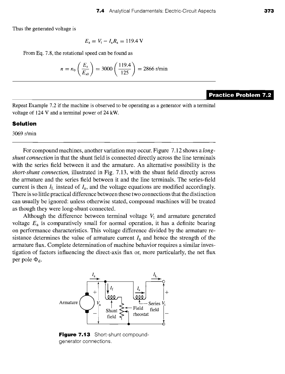
For compound machines, another variation may occur. Figure 7.12 shows a
long-
shunt connection
in that the shunt field is connected directly across the line terminals
with the series field between it and the armature. An alternative possibility is the
short-shunt connection,
illustrated in Fig. 7.13, with the shunt field directly across
the armature and the series field between it and the line terminals. The series-field
current is then IL instead of la, and the voltage equations are modified accordingly.
There is so little practical difference between these two connections that the distinction
can usually be ignored: unless otherwise stated, compound machines will be treated
as though they were long-shunt connected.
Although the difference between terminal voltage Vt and armature generated
voltage Ea is comparatively small for normal operation, it has a definite bearing
on performance characteristics. This voltage difference divided by the armature re-
sistance determines the value of armature current Ia and hence the strength of the
armature flux. Complete determination of machine behavior requires a similar inves-
tigation of factors influencing the direct-axis flux or, more particularly, the net flux
per pole @d.
/a /L
Figure 7.13
Short-shunt compound-
generator connections.
374 CHAPTER 7
DC Machines
7.5 ANALYTICAL FUNDAMENTALS:
MAGNETIC-CIRCUIT ASPECTS
The net flux per pole is that resulting from the combined mmf's of the field and
armature windings. Although in a idealized, shunt- or separately-excited dc machine
the armature mmf produces magnetic flux only along the quadrature axis, in a practical
device the armature current produces flux along the direct axis, either directly as
produced, for example, by a series field winding or indirectly through saturation
effects as discussed in Section 7.3. The interdependence of the generated armature
voltage Ea and magnetic circuit conditions in the machine is accordingly a function
of the sum of all the mmf's on the polar- or direct-axis flux path. First we consider
the mmf intentionally placed on the stator main poles to create the working flux, i.e.,
the
main-field mmf,
and then we include armature-reaction effects.
7.5.1 Armature Reaction Neglected
With no load on the machine or with armature-reaction effects ignored, the resultant
mmf is the algebraic sum of the mmf's acting on the main or direct axis. For the usual
compound generator or motor having Nf shunt-field turns per pole and Ns series-field
turns per pole,
Main-field mmf =
Nf lf + Ns Is
(7.20)
Note that the mmf of the series field can either add to or subtract from that of the
shunt field; the sign convention of Eq. 7.20 is such that the mmf's add. For example,
in the long-shunt connection of Fig. 7.12, this would correspond to the cumulative
series-field connection in which Is = Ia. If the connection of this series field-winding
were to be reversed such that Is = -Ia, forming a differential series-field connection,
then the mmf of the series field would subtract from that of the shunt field.
Additional terms will appear in Eq. 7.20 when there are additional field windings
on the main poles and when, unlike the compensating windings of Section 7.9, they
are wound concentric with the normal field windings to permit specialized control.
When either the series or the shunt field is absent, the corresponding term in Eq. 7.20
naturally is omitted.
Equation 7.20 thus sums up in ampere-turns per pole the gross mmf of the main-
field windings acting on the main magnetic circuit. The magnetization curve for a
dc machine is generally given in terms of current in only the principal field winding,
which is almost invariably the shunt-field winding when one is present. The mmf units
of such a magnetization curve and of Eq. 7.20 can be made the same by one of two
rather obvious steps. The field current on the magnetization curve can be multiplied
by the turns per pole in that winding, giving a curve in terms of ampere-turns per pole;
or both sides of Eq. 7.20 can be divided by Nf, converting the units to the equivalent
current in the Nf coil alone which produces the same mmf. Thus
Gross mmf- If + ~ Is equivalent shunt-field amperes (7.21)
7.5 Analytical Fundamentals: Magnetic-Circuit Aspects
375
Mmf or shunt-field current, per unit
0 0.2 0.4 0.6 0.8 1.0 1.2 1.4 1.6 1.8
320 ..... i! ~ ...... illl[ [, l ija:=o[ ]_,~
280
[:~ii
:[[i ....... .[.fill( !.~'I[ ....... ''b/4 ....... .... ..........
::: i ''4..i .......... ' |i--{[ ...... :' ~"~ ~ 5 f[[:~:[["~: ~~ "~- " ] "- ~ :-+~" 'a --
600
--
:: !::i
240
[[[[[[i
220 ........ i ........ ~ ....
i J
> 200
e~o
180
> 160
140
120
100
80
60
40
20
1.2
ii/l ........... [ ............... i ........
iiii~~~~~2 I a= 400
........ ].
1.0
[[ ~ [[[][ ...... /~;....7__j
a-- 00 [
'[[.[][- i
........ -~/..T7 .....
l' ~,"I J, , ,~ 2 7
. ................ , ................ .................. :.:
~ ~ ~.o~ [...ii • ....... k :2.~_4_:ii[._i Speed for'ail curves : 'i200 rPm [-T-- 0.6
I0 I
b ~
..................... i
I i I I I i I I I i I l 0.4
, d~ ,~ {
....... [[[[[
Scale for mmf in A. turns per
-[[[[ [
i .......... pole based on 1000 shunt-field
.............. i
i e , ..................... t .............. ..... t,
~>t [7 ;[~!ii[~_~~[ turns per pole i [ ~ i ~ ~ .... T
..............
-'
0.2
t i i
......... I .....
i o
0 1.0 2.0 7.0 8.0 9.0 3.0 4.0 5.0 6.0
Shunt-field current, A
0 1,000 2,000 3,000 4,000 5,000 6,000 7,000 8,000 9,000
Mmf, A • turn/pole
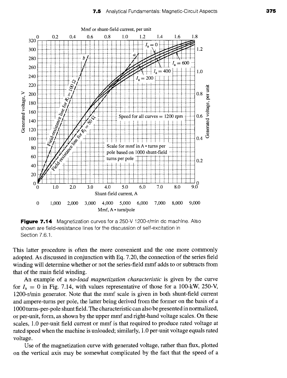
Figure
7.14 Magnetization curves for a 250-V 1200-r/min dc machine. Also
shown are field-resistance lines for the discussion of self-excitation in
Section 7.6.1.
This latter procedure is often the more convenient and the one more commonly
adopted. As discussed in conjunction with Eq. 7.20, the connection of the series field
winding will determine whether or not the series-field mmf adds to or subtracts from
that of the main field winding.
An example of a
no-load magnetization characteristic
is given by the curve
for Ia = 0 in Fig. 7.14, with values representative of those for a 100-kW, 250-V,
1200-r/min generator. Note that the mmf scale is given in both shunt-field current
and ampere-turns per pole, the latter being derived from the former on the basis of a
1000 turns-per-pole shunt field. The characteristic can also be presented in normalized,
or per-unit, form, as shown by the upper mmf and fight-hand voltage scales. On these
scales, 1.0 per-unit field current or mmf is that required to produce rated voltage at
rated speed when the machine is unloaded; similarly, 1.0 per-unit voltage equals rated
voltage.
Use of the magnetization curve with generated voltage, rather than flux, plotted
on the vertical axis may be somewhat complicated by the fact that the speed of a