Fitzgerald A.E. Electric Machinery
Подождите немного. Документ загружается.

376 CHAPTER 7 DC Machines
dc machine need not remain constant and that speed enters into the relation between
flux and generated voltage. Hence, generated voltage ordinates correspond to a unique
machine speed. The generated voltage Ea at any speed O)m is given by Eqs. 7.7 and
7.8, repeated here in terms of the steady-state values of generated voltage.
Ea=(Wrn) EaOogmO
(7.22)
or, in terms of rotational speed in r/min,
(no)
Ea = Ea0 (7.23)
In these equations,
O)m0
and no are the magnetizing-curve speed in rad/sec and r/min
respectively and Ea0 is the corresponding generated voltage.
-XAMPLE 7.:
A 100-kW, 250-V, 400-A, long-shunt compound generator has an armature resistance (including
brushes) of 0.025 g2, a series-field resistance of 0.005 ~, and the magnetization curve of
Fig. 7.14. There are 1000 shunt-field turns per pole and three series-field turns per pole. The
series field is connected in such a fashion that positive armature current produces direct-axis
mmf which adds to that of the shunt field.
Compute the terminal voltage at rated terminal current when the shunt-field current is
4.7 A and the speed is 1150 r/min. Neglect the effects of armature reaction.
II Solution
As is shown in Fig. 7.12, for a long-shunt connection the armature and series field-currents are
equal. Thus
Is = la = IL + If = 400+4.7 = 405 A
From Eq. 7.21 the main-field gross mmf is
Gross mmf = If + (-~) Is
= 4.7 + (10-~) 405 = 5.9 equivalent shunt-field amperes
By examining the la = 0 curve of Fig. 7.14 at this equivalent shunt-field current, one
reads a generated voltage of 274 V. Accordingly, the actual emf at a speed of 1150 r/min can
be found from Eq. 7.23
(n) (1150)
Ea = b Ea0 = 274 = 263 V
no
Then
Vt
= Ea -
la(ga + Rs) = 263 -405(0.025 + 0.005) = 251V
7.5
Analytical Fundamentals: Magnetic-Circuit Aspects
377
Repeat Example 7.3 for a terminal current of 375 A and a speed of 1190 r/min.
Solution
257 V
7.5.2 Effects of Armature Reaction Included
As described in Section 7.3, current in the armature winding gives rise to a demagne-
tizing effect caused by a cross-magnetizing armature reaction. Analytical inclusion of
this effect is not straightforward because of the nonlinearities involved. One common
approach is to base analyses on the measured performance of the machine in question
or for one of similar design and frame size. Data are taken with both the field and
armature excited, and the tests are conducted so that the effects on generated emf of
varying both the main-field excitation and the armature mmf can be noted.
One form of summarizing and correlating the results is illustrated in Fig. 7.14.
Curves are plotted not only for the no-load characteristic (I~ -- 0) but also for a family
of values of Ia. In the analysis of machine performance, the inclusion of armature
reaction then becomes simply a matter of using the magnetization curve corresponding
to the armature current involved. Note that the ordinates of all these curves give values
of armature-generated voltage Ea, not terminal voltage under load. Note also that all
the curves tend to merge with the air-gap line as the saturation of the iron decreases.
The load-saturation curves are displaced to the right of the no-load curve by an
amount which is a function of I~. The effect of armature reaction then is approximately
the same as a demagnetizing mmf Far acting on the main-field axis. This additional
term can then be included in Eq. 7.20, with the result that the net direct-axis mmf can
be assumed to be
Net mmf = gross mmf-
Far --
Nflf -Jr-
Nsls - AR
(7.24)
The no-load magnetization curve can then be used as the relation between gen-
erated emf and net excitation under load with the armature reaction accounted for as
a demagnetizing mmf. Over the normal operating range (about 240 to about 300 V
for the machine of Fig. 7.14), the demagnetizing effect of armature reaction may be
assumed to be approximately proportional to the armature current.
The reader should be aware that the amount of armature reaction present in
Fig. 7.14 is chosen so that some of its disadvantageous effects will appear in a pro-
nounced form in subsequent numerical examples and problems illustrating generator
and motor performance features. It is definitely more than one would expect to find
in a normal, well-designed machine operating at normal currents.
Consider again the long-shunt compound dc generator of Example 7.3. As in Example 7.3,
compute the terminal voltage at rated terminal current when the shunt-field current is 4.7 A
and the speed is 1150 r/min. In this case however, include the effects of armature reaction.
EXAMPLE 7.4
378 CHAPTER 7 DC Machines
II
Solution
As calculated in Example 7.3, Is = la = 400 A and the gross mmf is equal to 5.9 equivalent
shunt-field amperes. From the curve labeled Ia = 400 in Fig. 7.14 (based upon a rated terminal
current of 400 A), the corresponding generated emf is found to be 261 V (as compared to 274 V
with armature reaction neglected). Thus from Eq. 7.23, the actual generated voltage at a speed
of 1150 r/min is equal to
(n) (1150)
Ea -- --
Ea0 = 261 = 250 V
no ~]
Then
Vt
-- Ea - la(Ra +
Rs) = 250 - 405(0.025 + 0.005) = 238 V
-XAMPLE 7.!
To counter the effects of armature reaction, a fourth turn is added to the series field winding
of the dc generator of Examples 7.3 and 7.4, increasing its resistance to 0.007 g2. Repeat the
terminal-voltage calculation of Example 7.4.
n Solution
As in Examples 7.3 and 7.4, Is = la = 405 A. The main-field mmf can then be calculated as
(~ff) (4)
Gross mmf
= If -+- Ns
/~ = 4.7 + ~ 405
= 6.3 equivalent shunt-field amperes
From the la = 400 curve of Fig. 7.14 with an equivalent shunt-field current of 6.3 A, one
reads a generated voltage 269 V which corresponds to an emf at 1150 r/min of
1150)
Ea
= ~
269 = 258 V
The terminal voltage can now be calculated as
Vt = Ea - la (Ra + Rs) = 258 - 405(0.025 + 0.007) -- 245 V
Repeat Example 7.5 assuming that a fifth turn is added to the series field winding, bringing its
total resistance to 0.009 if2.
Solution
250 V
7.6 Analysis of Steady-State Performance 379
7.6
ANALYSIS OF STEADY-STATE
PERFORMANCE
Although exactly the same principles apply to the analysis of a dc machine acting as
a generator as to one acting as a motor, the general nature of the problems ordinarily
encountered is somewhat different for the two methods of operation. For a generator,
the speed is usually fixed by the prime mover, and problems often encountered are
to determine the terminal voltage corresponding to a specified load and excitation or
to find the excitation required for a specified load and terminal voltage. For a motor,
however, problems frequently encountered are to determine the speed corresponding
to a specific load and excitation or to find the excitation required for specified load and
speed conditions; terminal voltage is often fixed at the value of the available source.
The routine techniques of applying the common basic principles therefore differ to
the extent that the problems differ.
7.6.1 Generator Analysis
Since the main-field current is independent of the generator voltage, separately-excited
generators are the simplest to analyze. For a given load, the equivalent main-field
excitation is given by Eq. 7.21 and the associated armature-generated voltage Ea
is determined by the appropriate magnetization curve. This voltage, together with
Eq. 7.17 or 7.18, fixes the terminal voltage.
Shunt-excited generators will be found to self-excite under properly chosen oper-
ating conditions. Under these conditions, the generated voltage will build up sponta-
neously (typically initiated by the presence of a small amount of residual magnetism
in the field structure) to a value ultimately limited by magnetic saturation. In self-
excited generators, the shunt-field excitation depends on the terminal voltage and the
series-field excitation depends on the armature current. Dependence of shunt-field
current on terminal voltage can be incorporated graphically in an analysis by drawing
the
field-resistance line,
the line 0a in Fig. 7.14, on the magnetization curve. The
field-resistance line 0a is simply a graphical representation of Ohm's law applied
to the shunt field. It is the locus of the terminal voltage versus shunt-field-current
operating point. Thus, the line 0a is drawn for Rf -- 50 ~ and hence passes through
the origin and the point (1.0 A, 50 V).
The tendency of a shunt-connected generator to self-excite can be seen by exam-
ining the buildup of voltage for an unloaded shunt generator. When the field circuit
is closed, the small voltage from residual magnetism (the 6-V intercept of the mag-
netization curve, Fig. 7.14) causes a small field current. If the flux produced by the
resulting ampere-turns adds to the residual flux, progressively greater voltages and
field currents are obtained. If the field ampere-turns opposes the residual magnetism,
the shunt-field terminals must be reversed to obtain buildup.
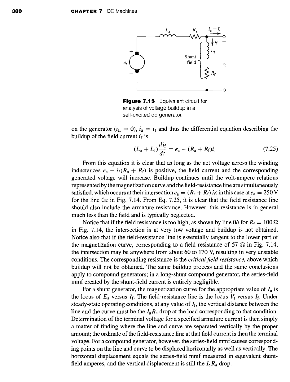
This process can be seen with the aid of Fig. 7.15. In Fig. 7.15, the generated
voltage ea is shown in series with the armature inductance La and resistance Ra. The
shunt-field winding, shown connected across the armature terminals, is represented
by its inductance Lf and resistance Rf. Recognizing that since there is no load current
380
CHAPTER
7 DC Machines
Z a
f"V"V"V~
R a i a -- 0
)~rif 4-
)
)
Lf
Shunt )
field vt
.~ Rf
Figure
7.15 Equivalent circuit for
analysis of voltage buildup in a
self-excited dc generator.
on the generator
(iL -- 0), ia -- if
and thus the differential equation describing the
buildup of the field current if is
dif
(La -q- Lf) --7- -- ea - (ga -+- Rf)if (7.25)
dt
From this equation it is clear that as long as the net voltage across the winding
inductances
ea -- if(Ra q- Rf)
is positive, the field current and the corresponding
generated voltage will increase. Buildup continues until the volt-ampere relations
represented by the magnetization curve and the field-resistance line are simultaneously
satisfied, which occurs at their intersection ea - (Ra -k- Rf) if; in this case at ea - 250 V
for the line 0a in Fig. 7.14. From Eq. 7.25, it is clear that the field resistance line
should also include the armature resistance. However, this resistance is in general
much less than the field and is typically neglected.
Notice that if the field resistance is too high, as shown by line 0b for Re --
100
in Fig. 7.14, the intersection is at very low voltage and buildup is not obtained.
Notice also that if the field-resistance line is essentially tangent to the lower part of
the magnetization curve, corresponding to a field resistance of 57 f2 in Fig. 7.14,
the intersection may be anywhere from about 60 to 170 V, resulting in very unstable
conditions. The corresponding resistance is the
critical field resistance,
above which
buildup will not be obtained. The same buildup process and the same conclusions
apply to compound generators; in a long-shunt compound generator, the series-field
mmf created by the shunt-field current is entirely negligible.
For a shunt generator, the magnetization curve for the appropriate value of Ia is
the locus of Ea versus If. The field-resistance line is the locus Vt versus If. Under
steady-state operating conditions, at any value of If, the vertical distance between the
line and the curve must be the la
Ra
drop at the load corresponding to that condition.
Determination of the terminal voltage for a specified armature current is then simply
a matter of finding where the line and curve are separated vertically by the proper
amount; the ordinate of the field-resistance line at that field current is then the terminal
voltage. For a compound generator, however, the series-field mmf causes correspond-
ing points on the line and curve to be displaced horizontally as well as vertically. The
horizontal displacement equals the series-field mmf measured in equivalent shunt-
field amperes, and the vertical displacement is still the la Ra drop.
7.6 Analysis of Steady-State Performance 381
Great precision is evidently not obtained from the foregoing computational pro-
cess. The uncertainties caused by magnetic hysteresis in dc machines make high
precision unattainable in any event. In general, the magnetization curve on which the
machine operates on any given occasion may range from the rising to the falling part
of the rather fat hysteresis loop for the magnetic circuit of the machine, depending
essentially on the magnetic history of the iron. The curve used for analysis is usually
the mean magnetization curve, and thus the results obtained are substantially correct
on the average. Significant departures from the average may be encountered in the
performance of any dc machine at a particular time, however.
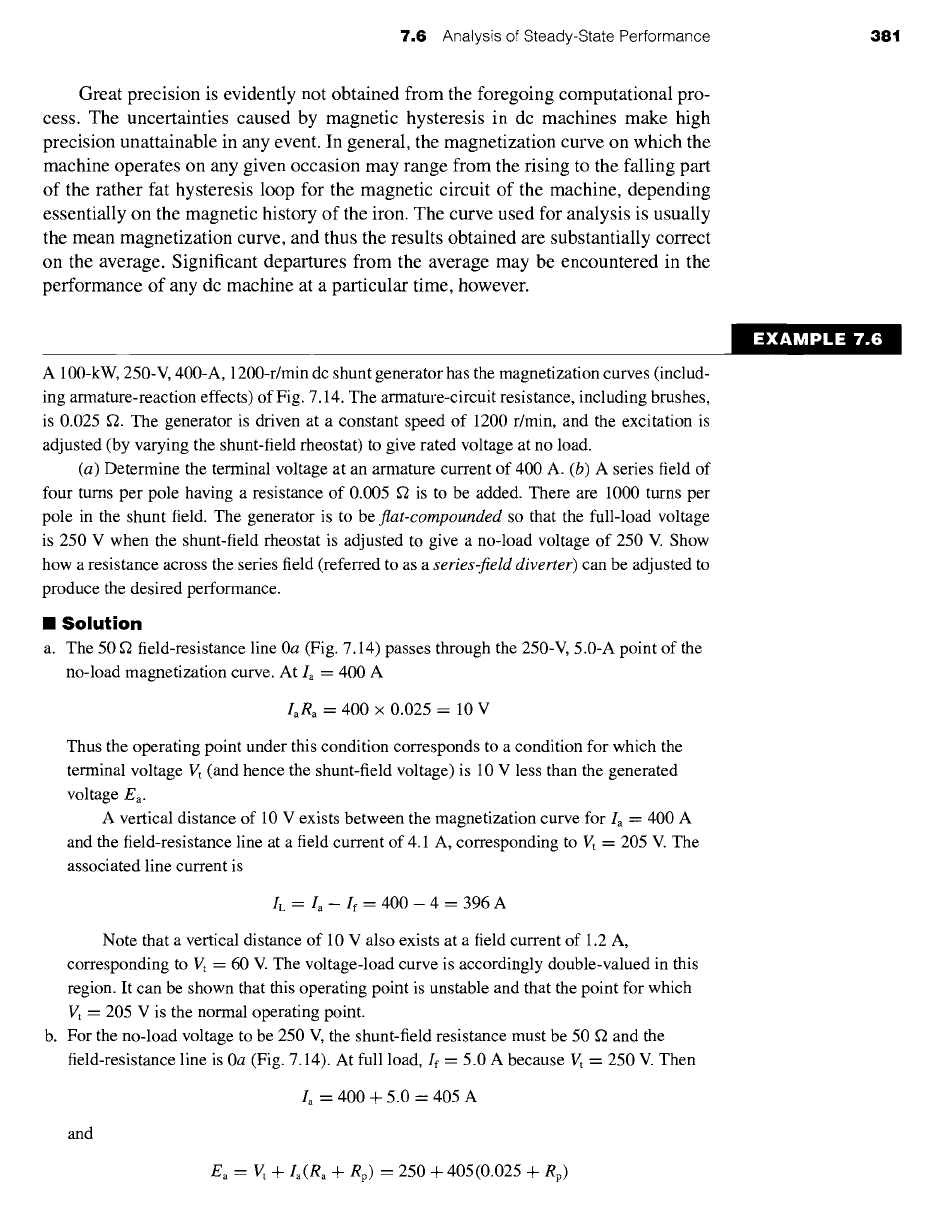
A 100-kW, 250-V, 400-A, 1200-r/min dc shunt generator has the magnetization curves (includ-
ing armature-reaction effects) of Fig. 7.14. The armature-circuit resistance, including brushes,
is 0.025 ~2. The generator is driven at a constant speed of 1200 r/min, and the excitation is
adjusted (by varying the shunt-field rheostat) to give rated voltage at no load.
(a) Determine the terminal voltage at an armature current of 400 A. (b) A series field of
four turns per pole having a resistance of 0.005 ~ is to be added. There are 1000 turns per
pole in the shunt field. The generator is to be
flat-compounded
so that the full-load voltage
is 250 V when the shunt-field rheostat is adjusted to give a no-load voltage of 250 V. Show
how a resistance across the series field (referred to as a
series-field diverter)
can be adjusted to
produce the desired performance.
II
Solution
a. The 50 ~ field-resistance line 0a (Fig. 7.14) passes through the 250-V, 5.0-A point of the
no-load magnetization curve. At Ia = 400 A
IaR,
= 400 x 0.025 = 10 V
Thus the operating point under this condition corresponds to a condition for which the
terminal voltage Vt (and hence the shunt-field voltage) is 10 V less than the generated
voltage Ea.
A vertical distance of 10 V exists between the magnetization curve for I~ = 400 A
and the field-resistance line at a field current of 4.1 A, corresponding to Vt = 205 V. The
associated line current is
IL = /~- If = 400--4 = 396A
Note that a vertical distance of 10 V also exists at a field current of 1.2 A,
corresponding to Vt -- 60 V. The voltage-load curve is accordingly double-valued in this
region. It can be shown that this operating point is unstable and that the point for which
Vt = 205 V is the normal operating point.
b. For the no-load voltage to be 250 V, the shunt-field resistance must be 50 fl and the
field-resistance line is 0a (Fig. 7.14). At full load, If = 5.0 A because Vt = 250 V. Then
/~ = 400 + 5.0 = 405 A
and
E, = Vt +/~(Ra + Rp) = 250 + 405(0.025 + Rp)
EXAMPLE 7.6
382 CHAPTER 7 DC Machines
where
Rp
is the parallel combination of the series-field resistance R~ = 0.005 fl and the
diverter resistance Rd
RsRd
Rp -- (Rs + Rd)
The series field and the diverter resistor are in parallel, and thus the shunt-field
current can be calculated as
(Rd) =405(Rp)
Is=405 R,+Rd -~s
and the equivalent shunt-field amperes can be calculated from Eq. 7.21 as
4 4
/net -- If+
1-~I~ = 5.0+ 1--6-0-6/s
= 5.0 + 1.62 (RRss)
This equation can be solved for
Rp
which can be, in turn, substituted (along with
Rs = 0.005 f2) in the equation for Ea to yield
Ea -- 253.9 + 1.251net
This can be plotted on Fig. 7.14 (Ea on the vertical axis and/net on the horizontal
axis). Its intersection with the magnetization characteristic for/a -- 400 A (strictly
speaking, of course, a curve for/a -- 405 A should be used, but such a small distinction is
obviously meaningless here) gives/net = 6.0 A.
Thus
Rs(Inet- 5.0)
Rp = 1.62 = 0.0031 f2
and
Rd = 0.0082 f2
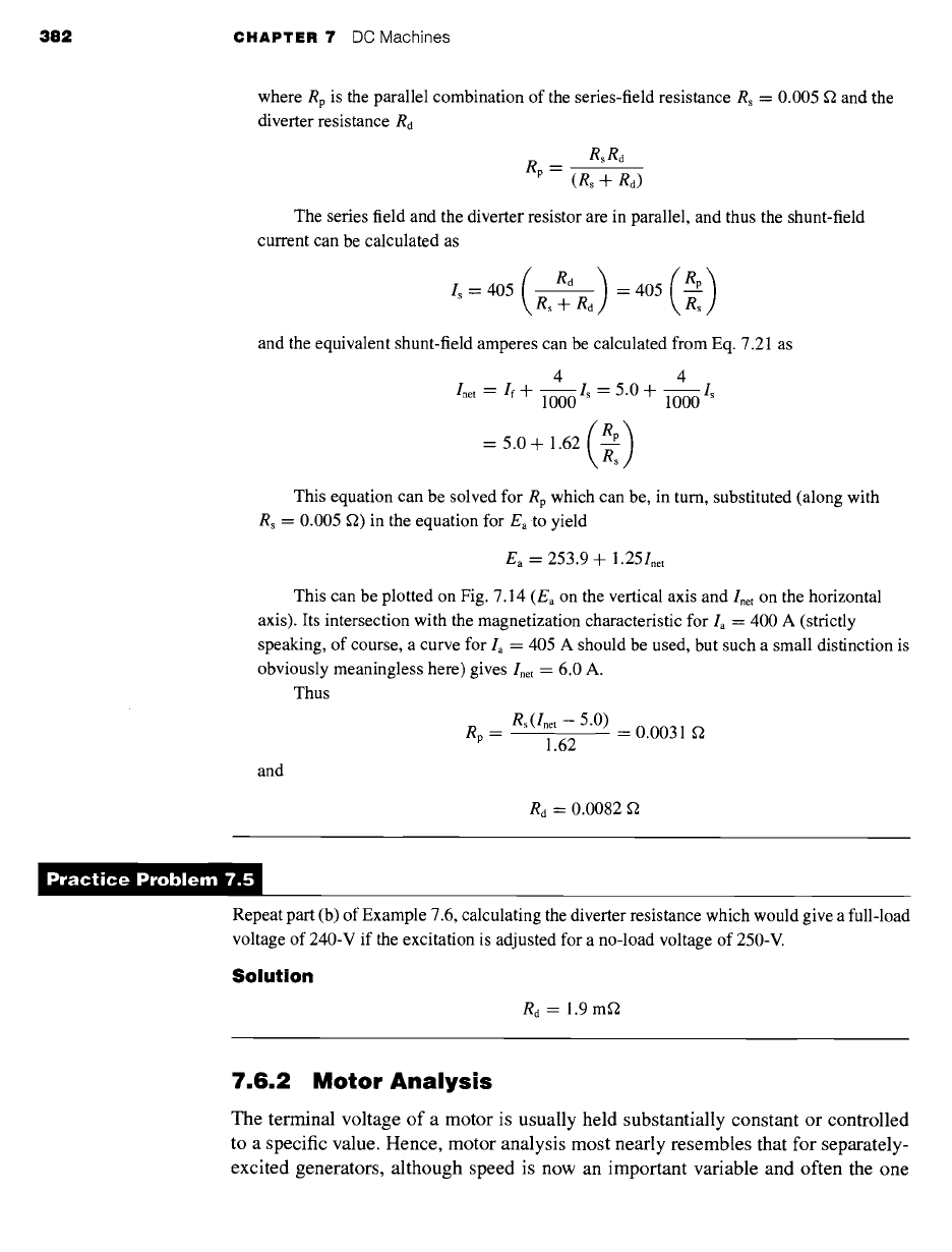
Repeat part (b) of Example 7.6, calculating the diverter resistance which would give a full-load
voltage of 240-V if the excitation is adjusted for a no-load voltage of 250-V.
Solution
Rd = 1.9 mr2
7.6.2 Motor Analysis
The terminal voltage of a motor is usually held substantially constant or controlled
to a specific value. Hence, motor analysis most nearly resembles that for separately-
excited generators, although speed is now an important variable and often the one
7.6 Analysis of Steady-State Performance 383
whose value is to be found. Analytical essentials include Eqs. 7.17 and 7.18 relating
terminal voltage and generated voltage (counter emf); Eq. 7.21 for the main-field
excitation; the magnetization curve for the appropriate armature current as the graph-
ical relation between counter emf and excitation; Eq. 7.13 showing the dependence
of electromagnetic torque on flux and armature current; and Eq. 7.14 relating counter
emf to flux and speed. The last two relations are particularly significant in motor
analysis. The former is pertinent because the interdependence of torque and the sta-
tor and rotor field strengths must often be examined. The latter is the usual medium
for determining motor speed from other specified operating conditions.
Motor speed corresponding to a given armature current la can be found by first
computing the actual generated voltage Ea from Eq. 7.17 or 7.18. Next the main-field
excitation can be obtained from Eq. 7.21. Since the magnetization curve will be plotted
for a constant speed corn0, which in general will be different from the actual motor
speed tom, the generated voltage read from the magnetization curve at the foregoing
main-field excitation will correspond to the correct flux conditions but to speed tom0.
Substitution in Eq. 7.22 then yields the actual motor speed.
Note that knowledge of the armature current is postulated at the start of this
process. When, as is frequently the case, the speed at a stated shaft power or torque
output is to be found, an iterative procedure based on assumed values of Ia usually
forms the basis for finding the solution.
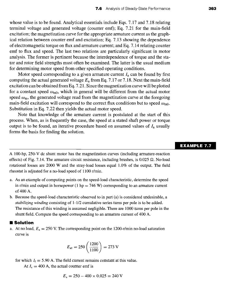
A 100-hp, 250-V dc shunt motor has the magnetization curves (including armature-reaction
effects) of Fig. 7.14. The armature circuit resistance, including brushes, is 0.025 ~2. No-load
rotational losses are 2000 W and the stray-load losses equal 1.0% of the output. The field
rheostat is adjusted for a no-load speed of 1100 r/min.
a. As an example of computing points on the speed-load characteristic, determine the speed
in r/min and output in horsepower (1 hp = 746 W) corresponding to an armature current
of 400 A.
b. Because the speed-load characteristic observed to in part (a) is considered undesirable, a
stabilizing winding
consisting of 1-1/2 cumulative series turns per pole is to be added.
The resistance of this winding is assumed negligible. There are 1000 turns per pole in the
shunt field. Compute the speed corresponding to an armature current of 400 A.
II
Solution
a. At no load, Ea -- 250 V. The corresponding point on the 1200-r/min no-load saturation
curve is
(1200)
Ea0 = 250 1-~ =- 273 V
for which If = 5.90 A. The field current remains constant at this value.
At Ia = 400 A, the actual counter emf is
Ea = 250- 400 × 0.025 = 240 V
EXAMPLE 7.7
384 CHAPTER 7 DC Machines
From Fig. 7.14 with la = 400 and If = 5.90, the value of Ea would be 261 V if the speed
were 1200 r/min. The actual speed is then found from Eq. 7.23
n = 1200 \ 261 = 1100 r/min
The electromagnetic power is
E, Ia
= 240 x 400 = 96 kW
Deduction of the rotational losses leaves 94 kW. With stray load losses accounted for, the
power output P0 is given by
94 kW - 0.01 P0 = P0
or
Po = 93.1 kW = 124.8 hp
Note that the speed at this load is the same as at no load, indicating that armature-
reaction effects have caused an essentially fiat speed-load curve.
b. With If = 5.90 A and Is = la = 400 A, the main-field mmf in equivalent shunt-field
amperes is
(
1.5 )
5.90 + k, 400 = 6.50 A
From Fig. 7.14 the corresponding value of Ea at 1200 r/min would be 271 V. Accordingly,
the speed is now
/
n=1200\~ =1063r/min
The power output is the same as in part (a). The speed-load curve is now drooping, due to
the effect of the stabilizing winding.
Repeat Example 7.7 for an armature current of la = 200 A.
Solution
a. Speed = 1097 r/min and P0 = 46.5 kW = 62.4 hp
b. Speed = 1085 r/min
7.7 PERMANENT-MAGNET DC MACHINES
Permanent-magnet dc machines are widely found in a wide variety of low-power
applications. The field winding is replaced by a permanent magnet, resulting in
simpler construction. Permanent magnets offer a number of useful benefits in these
7.7 Permanent-Magnet DC Machines 385
applications. Chief among these is that they do not require external excitation and its
associated power dissipation to create magnetic fields in the machine. The space re-
quired for the permanent magnets may be less than that required for the field winding,
and thus permanent-magnet machines may be smaller, and in some cases cheaper,
than their externally-excited counterparts.
Alternatively, permanent-magnet dc machines are subject to limitations imposed
by the permanent magnets themselves. These include the risk of demagnetization
due to excessive currents in the motor windings or due to overheating of the magnet.
In addition, permanent magnets are somewhat limited in the magnitude of air-gap
flux density that they can produce. However, with the development of new magnetic
materials such as samarium-cobalt and neodymium-iron-boron (Section 1.6), these
characteristics are becoming less and less restrictive for permanent-magnet machine
design.
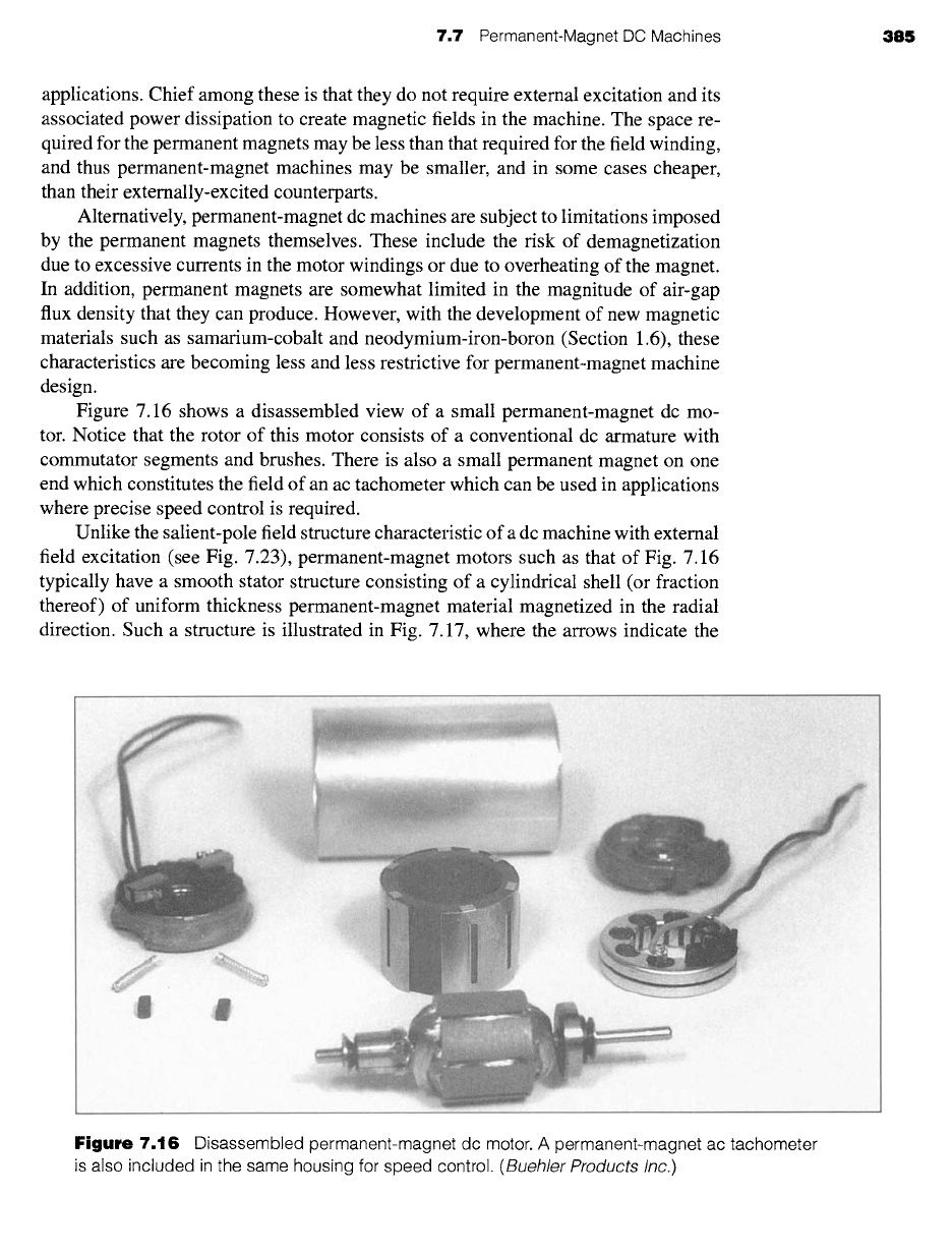
Figure 7.16 shows a disassembled view of a small permanent-magnet dc mo-
tor. Notice that the rotor of this motor consists of a conventional dc armature with
commutator segments and brushes. There is also a small permanent magnet on one
end which constitutes the field of an ac tachometer which can be used in applications
where precise speed control is required.
Unlike the salient-pole field structure characteristic of a dc machine with external
field excitation (see Fig. 7.23), permanent-magnet motors such as that of Fig. 7.16
typically have a smooth stator structure consisting of a cylindrical shell (or fraction
thereof) of uniform thickness permanent-magnet material magnetized in the radial
direction. Such a structure is illustrated in Fig. 7.17, where the arrows indicate the
Figure
7.16 Disassembled permanent-magnet dc motor. A permanent-magnet ac tachometer
is also included in the same housing for speed control.
(Buehler Products Inc.)