Fitzgerald A.E. Electric Machinery
Подождите немного. Документ загружается.

386 CHAPTER 7 DC Machines
Radially magnetized
permanent magnets
(arrows indicate direction
of magnetization)
Figure
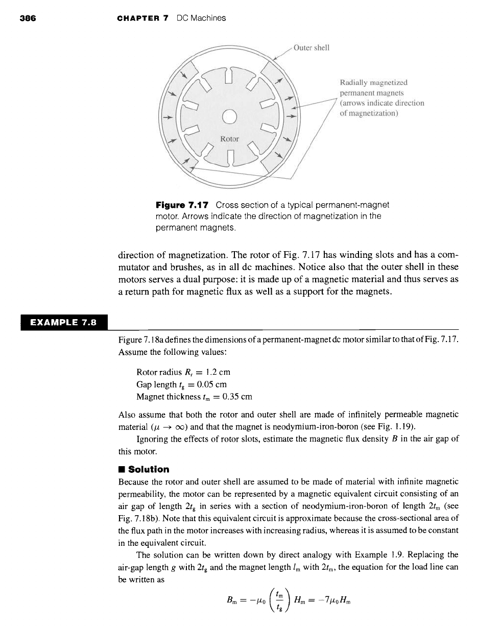
7.17 Cross section of a typical permanent-magnet
motor. Arrows indicate the direction of magnetization in the
permanent magnets.
direction of magnetization. The rotor of Fig. 7.17 has winding slots and has a com-
mutator and brushes, as in all dc machines. Notice also that the outer shell in these
motors serves a dual purpose: it is made up of a magnetic material and thus serves as
a return path for magnetic flux as well as a support for the magnets.
EXAMPLE 7.8
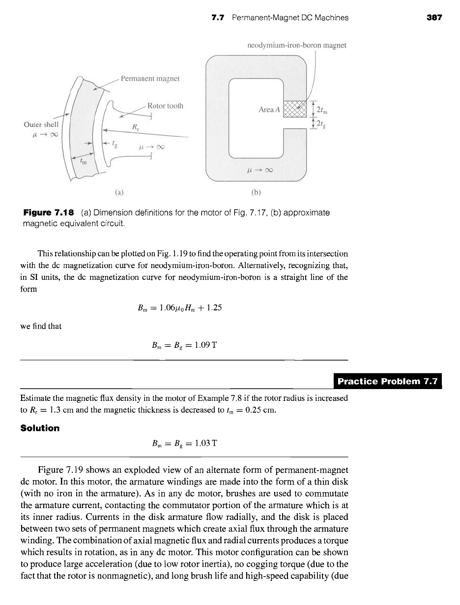
Figure 7.18a defines the dimensions of a permanent-magnet dc motor similar to that of Fig. 7.17.
Assume the following values:
Rotor radius Rr -- 1.2 cm
Gap length tg = 0.05 cm
Magnet thickness tm = 0.35 cm
Also assume that both the rotor and outer shell are made of infinitely permeable magnetic
material (# ~ c¢) and that the magnet is neodymium-iron-boron (see Fig. 1.19).
Ignoring the effects of rotor slots, estimate the magnetic flux density B in the air gap of
this motor.
II
Solution
Because the rotor and outer shell are assumed to be made of material with infinite magnetic
permeability, the motor can be represented by a magnetic equivalent circuit consisting of an
air gap of length 2tg in series with a section of neodymium-iron-boron of length 2tm (see
Fig. 7.18b). Note that this equivalent circuit is approximate because the cross-sectional area of
the flux path in the motor increases with increasing radius, whereas it is assumed to be constant
in the equivalent circuit.
The solution can be written down by direct analogy with Example 1.9. Replacing the
air-gap length g with 2tg and the magnet length lm with 2tm, the equation for the load line can
be written as
Bm -- -/z0 nm= -7#0nm
7.7 Permanent-Magnet DC Machines 387
neodymium-iron-boron magnet
t magnet
Outer
she
/z --+ c
otor tooth
~CX~
2tm
2tg
(a) (b)
Figure
7.18 (a) Dimension definitions for the motor of Fig. 7.17, (b) approximate
magnetic equivalent circuit.
This relationship can be plotted on Fig. 1.19 to find the operating point from its intersection
with the dc magnetization curve for neodymium-iron-boron. Alternatively, recognizing that,
in SI units, the dc magnetization curve for neodymium-iron-boron is a straight line of the
form
Bm = 1.06#oHm + 1.25
we find that
Bm= Bg -- 1.09 T
)ractice Problem 7.
Estimate the magnetic flux density in the motor of Example 7.8 if the rotor radius is increased
to Rr -- 1.3 cm and the magnetic thickness is decreased to tm = 0.25 cm.
Solution
Bm = Bg ----- 1.03 T
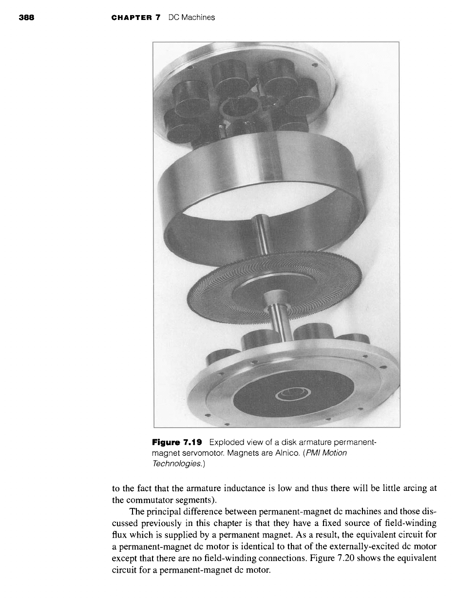
Figure 7.19 shows an exploded view of an alternate form of permanent-magnet
dc motor. In this motor, the armature windings are made into the form of a thin disk
(with no iron in the armature). As in any dc motor, brushes are used to commutate
the
armature current, contacting the commutator portion of the armature which is at
its inner radius. Currents in the disk armature flow radially, and the disk is placed
between two sets of permanent magnets which create axial flux through the armature
winding. The combination of axial magnetic flux and radial currents produces a torque
which results in rotation, as in any dc motor. This motor configuration can be shown
to produce large acceleration (due to low rotor inertia), no cogging torque (due to the
fact that the rotor is nonmagnetic), and long brush life and high-speed capability (due
388 CHAPTER 7 DC Machines
Figure
7.19 Exploded view of a disk armature permanent-
magnet servomotor. Magnets are Alnico.
(PMI Motion
Technologies.)
to the fact that the armature inductance is low and thus there will be little arcing at
the commutator segments).
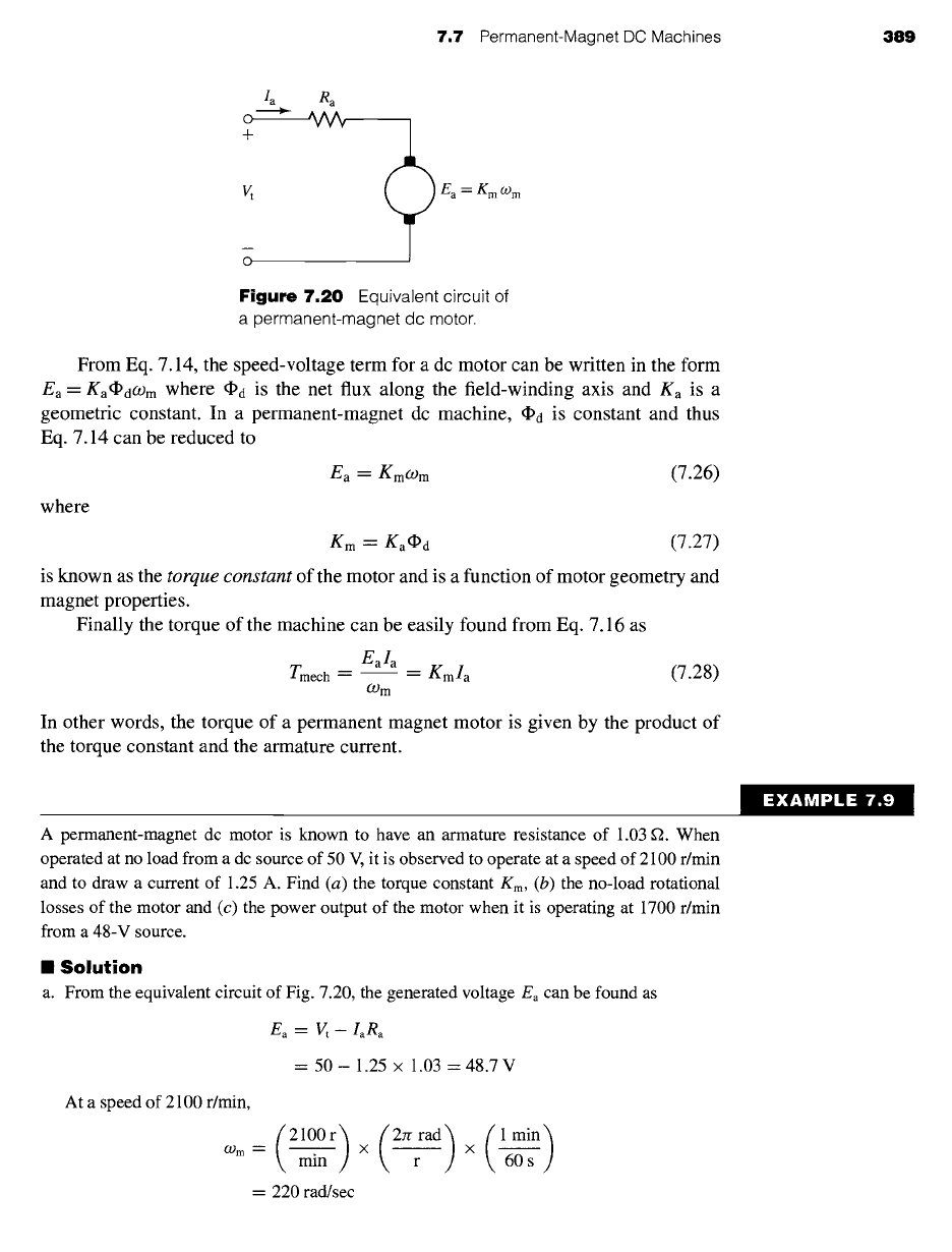
The principal difference between permanent-magnet dc machines and those dis-
cussed previously in this chapter is that they have a fixed source of field-winding
flux which is supplied by a permanent magnet. As a result, the equivalent circuit for
a permanent-magnet dc motor is identical to that of the externally-excited dc motor
except that there are no field-winding connections. Figure 7.20 shows the equivalent
circuit for a permanent-magnet dc motor.
7.7
Permanent-Magnet DC Machines 389
Ia R a
o------~ ,V~
+
V t Ea = Kmogm
0
Figure 7.20
Equivalent circuit
of
a permanent-magnet dc motor.
From Eq. 7.14, the speed-voltage term for a dc motor can be written in the form
Ea = Ka~dCOm where ~a is the net flux along the field-winding axis and Ka is a
geometric constant. In a permanent-magnet dc machine, ~a is constant and thus
Eq. 7.14 can be reduced to
Ea-- Kmogm (7.26)
where
Km = Ka~d (7.27)
is known as the
torque constant
of the motor and is a function of motor geometry and
magnet properties.
Finally the torque of the machine can be easily found from Eq. 7.16 as
Eala
Tmech- =
Kmla
(7.28)
O)m
In other words, the torque of a permanent magnet motor is given by the product of
the torque constant and the armature current.
"XAMPLE 7.!
A permanent-magnet dc motor is known to have an armature resistance of 1.03 g2. When
operated at no load from a dc source of 50 V, it is observed to operate at a speed of 2100 r/min
and to draw a current of 1.25 A. Find (a) the torque constant
Km, (b)
the no-load rotational
losses of the motor and (c) the power output of the motor when it is operating at 1700 r/min
from a 48-V source.
II
Solution
a. From the equivalent circuit of Fig. 7.20, the generated voltage Ea can be found as
Ea = Vt-IaRa
= 50- 1.25 × 1.03 = 48.7 V
At a speed of 2100 r/min,
(2100r) (2rrrad)(1 man)
09 m
-" X X
min 60 s
= 220 rad/sec
390 CHAPTER 7 DC Machines
Therefore, from Eq. 7.26,
Ea
48.7
Km = -- = 0.22
V/(rad/sec)
O) m 220
b. At no load, all the power supplied to the generated voltage Ea is used to supply rotational
losses. Therefore
Rotational losses =
Eala "--
48.7 x 1.25 = 61 W
c. At 1700 r/min,
O.) m =
1700 = 178 rad/sec
and
Ea = Km(.Om = 0.22 x 178 = 39.2 V
The input current can now be found as
Vt - Ea
48-
39.2
/a= --
Ra 1.03
= 8.54 A
The electromagnetic power can be calculated as
Pmech =--
Eala
-- 39.2 X 8.54 = 335 W
Assuming the rotational losses to be constant at their no-load value (certainly an
approximation), the output shaft power can be calculated:
Pshaft -- Pmech --
rotational losses = 274 W
The armature resistance of a small dc motor is measured to be 178 mr2. With an applied voltage
of 9 V, the motor is observed to operate at a no-load speed of 14,600 r/min while drawing a
current of 437 mA. Calculate (a) the rotational loss and (b) the motor torque constant Kin.
Solution
a. Rotational loss = 3.90 W
b.
Km =
5.84
x 10 .3
V/(rad/sec)
7.8 COMMUTATION AND INTERPOLES
One of the most important limiting factors on the satisfactory operation of a dc machine
is the ability to transfer the necessary armature current through the brush contact at the
commutator without sparking and without excessive local losses and heating of the
brushes and commutator. Sparking causes destructive blackening, pitting, and wear
of both the commutator and the brushes, conditions which rapidly become worse
and burn away the copper and carbon. Sparking may be caused by faulty mechanical
7,8 Commutation and Interpoles 39t
conditions, such as chattering of the brushes or a rough, unevenly worn commutator,
or, as in any switching problem, by electrical conditions. The latter conditions are
seriously influenced by the armature mmf and the resultant flux wave.
As indicated in Section 7.2, a coil undergoing commutation is in transition be-
tween two groups of armature coils: at the end of the commutation period, the coil cur-
rent must be equal but opposite to that at the beginning. Figure 7.7b shows the armature
in an intermediate position during which the coils in slots 1 and 7 are being commu-
tated. The commutated coils are short-circuited by the brushes. During this period the
brushes must continue to conduct the armature current Ia from the armature winding to
the external circuit. The short-circuited coil constitutes an inductive circuit with time-
varying resistances at the brush contact, with rotational voltages induced in the coil,
and with both conductive and inductive coupling to the rest of the armature winding.
The attainment of good commutation is more an empirical art than a quantitative
science. The principal obstacle to quantitative analysis lies in the electrical behavior of
the carbon-copper (brush-commutator) contact film. Its resistance is nonlinear and is
a function of current density, current direction, temperature, brush material, moisture,
and atmospheric pressure. Its behavior in some respects is like that of an ionized gas or
plasma. The most significant fact is that an unduly high current density in a portion of
the brush surface (and hence an unduly high energy density in that part of the contact
film) results in sparking and a breakdown of the film at that point. The boundary film
also plays an important part in the mechanical behavior of the rubbing surfaces. At
high altitudes, definite steps must be taken to preserve it, or extremely-rapid brush
wear takes place.
The empirical basis of securing sparkless commutation, then, is to avoid excessive
current densities at any point in the copper-carbon contact. This basis, combined with
the principle of utilizing all material to the fullest extent, indicates that optimum
conditions are obtained when the current density is uniform over the brush surface
during the entire commutation period. A linear change of current with time in the
commutated coil, corresponding to linear commutation as shown in Fig. 7.8, brings
about this condition and is accordingly the optimum.
The principal factors tending to produce linear commutation are changes in brush-
contact resistance resulting from the linear decrease in area at the trailing brush edge
and linear increase in area at the leading edge. Several electrical factors mitigate
against linearity. Resistance in the commutated coil is one example. Usually, however,
the voltage drop at the brush contacts is sufficiently large (of the order of 1.0 V) in
comparison with the resistance drop in a single armature coil to permit the latter
to be ignored. Coil inductance is a much more serious factor. Both the voltage of
self-induction in the commutated coil and the voltage of mutual-induction from other
coils (particularly those in the same slot) undergoing commutation at the same time
oppose changes in current in the commutated coil. The sum of these two voltages is
often referred to as the
reactance voltage.
Its result is that current values in the short-
circuited coil lag in time the values dictated by linear commutation. This condition is
known as
undercommutation
or
delayed commutation.
Armature inductance thus tends to produce high losses and sparking at the trailing
brush tip. For best commutation, inductance must be held to a minimum by using the
fewest possible number of turns per armature coil and by using a multipolar design
392 CHAPTER 7 DC Machines
with a short armature. The effect of a given reactance voltage in delaying commutation
is minimized when the resistive brush-contact voltage drop is significant compared
with it. This fact is one of the main reasons for the use of carbon brushes with their
appreciable contact drop. When good commutation is secured by virtue of resistance
drops, the process is referred to as
resistance commutation.
It is typically used as the
exclusive means only in fractional-horsepower machines.
Another important factor in the commutation process is the rotational voltage in-
duced in the short-circuited coil. Depending on its sign, this voltage may hinder or aid
commutation. In Fig. 7.11, for example, cross-magnetizing armature reaction creates
a definite flux in the interpolar region. The direction of the corresponding rotational
voltage in the commutated coil is the same as the current under the immediately pre-
ceding pole face. This voltage then encourages the continuance of current in the old
direction and, like the resistance voltage, opposes its reversal. To aid commutation,
the rotational voltage must oppose the reactance voltage. The general principle is
to produce in the coil undergoing commutation a rotational voltage which approxi-
mately compensates for the reactance voltage, a principle called
voltage commutation.
Voltage commutation is used in almost all modern integral-horsepower commutating
machines. The appropriate flux density is introduced in the commutating zone by
means of small, narrow poles located between the main poles. These auxiliary poles
are called
interpoles
or
commutating poles.
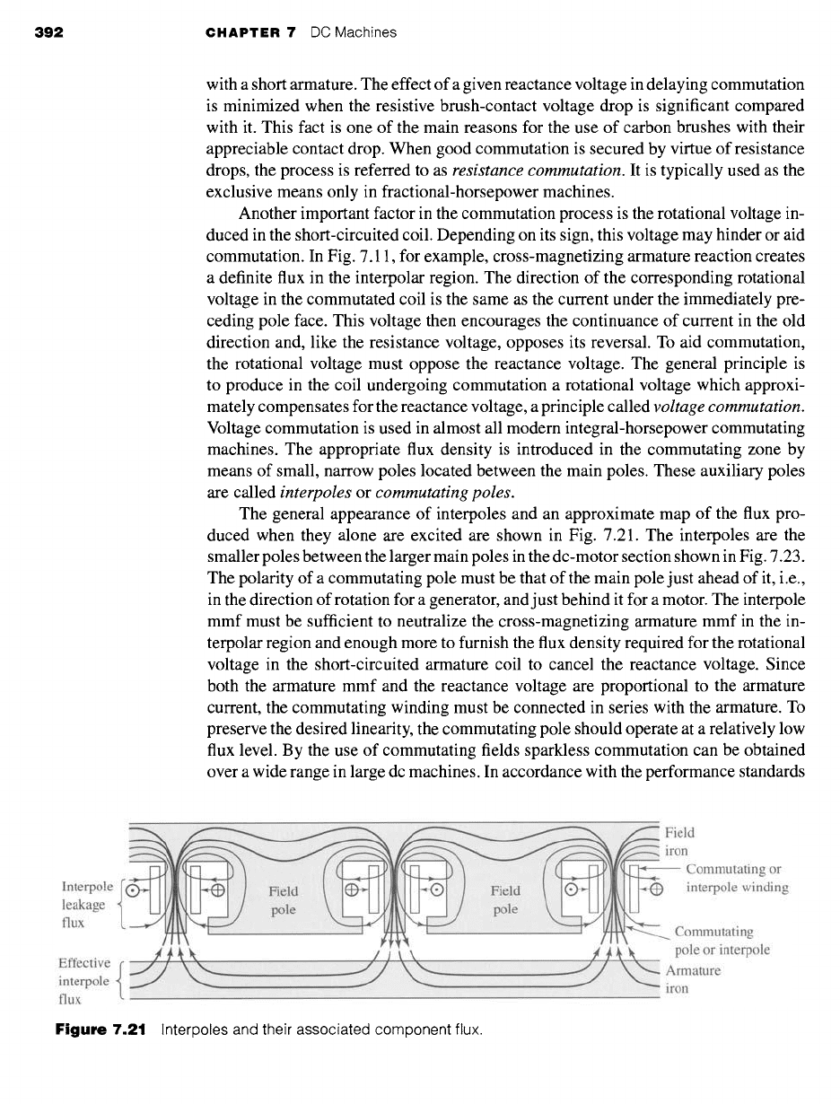
The general appearance of interpoles and an approximate map of the flux pro-
duced when they alone are excited are shown in Fig. 7.21. The interpoles are the
smaller poles between the larger main poles in the dc-motor section shown in Fig. 7.23.
The polarity of a commutating pole must be that of the main pole just ahead of it, i.e.,
in the direction of rotation for a generator, and just behind it for a motor. The interpole
mmf must be sufficient to neutralize the cross-magnetizing armature mmf in the in-
terpolar region and enough more to furnish the flux density required for the rotational
voltage in the short-circuited armature coil to cancel the reactance voltage. Since
both the armature mmf and the reactance voltage are proportional to the armature
current, the commutating winding must be connected in series with the armature. To
preserve the desired linearity, the commutating pole should operate at a relatively low
flux level. By the use of commutating fields sparkless commutation can be obtained
over a wide range in large dc machines. In accordance with the performance standards
Interpole {
leakage
flux
Effective(~/ \
interpole
flux
...............................................................
Field
~I) iron
i Commutating or
:i~ Field interpole winding
j ~ii~
pole
~.£Z~' !i~ii!i!iiiil iliii
" .....E-,
Commutating
~, pole or interpole
Armature
iron
Figure
7.21 Interpoles and their associated component flux.
7.9
Compensating Windings 393
of NEMA, 1 general-purpose dc machines must be capable of carrying for one minute,
with successful commutation, loads of 150 percent of the current corresponding to
their continuous rating when operating with a field current equal to their rated-load
excitation.
7.9 COMPENSATING WINDINGS
For machines subjected to heavy overloads, rapidly changing loads, or operation with
a weak main field, there is the possibility of trouble other than simply sparking at
the brushes. At the instant when an armature coil is located at the peak of a badly
distorted flux wave, the coil voltage may be high enough to break down the air
between the adjacent segments to which the coil is connected and result in flashover,
or arcing, between segments. The breakdown voltage here is not high, because the
air near the commutator is in a condition favorable to breakdown, due to the presence
of the plasma carrying the armature current between the brushes and the commutator.
The maximum allowable voltage between segments is of the order of 30 to 40 V,
a fact which limits the average voltage between segments to lower values and thus
determines the minimum number of segments which can be used in a proposed design.
Under transient conditions, high voltages between segments may result from the
induced voltages associated with growth and decay of armature flux. Inspection of
Fig. 7.10, for instance, may enable one to visualize very appreciable voltages of
this nature being induced in a coil under the pole centers by the growth or decay
of the armature flux shown in the sketch. Consideration of the sign of this induced
voltage will show that it adds to the normal rotational emf when load is dropped
from a generator or added to a motor. Flashing between segments may quickly spread
around the entire commutator and, in addition to its possibly destructive effects on
the commutator, constitutes a direct short circuit on the line. Even with interpoles
present, therefore, armature reaction under the poles definitely limits the conditions
under which a machine can operate.
These limitations can be considerably extended by compensating or neutralizing
the armature mmf under the pole faces. Such compensation can be achieved by means
of a
compensating
or
pole-face winding
(Fig. 7.22) embedded in slots in the pole face
and having a polarity opposite to that of the adjoining armature winding. The physical
appearance of such a winding can be seen in the stator section of Fig. 7.23. Since the
axis of the compensating winding is the same as that of the armature, it will almost
completely neutralize the armature reaction of the armature conductors under the pole
faces when it is given the proper number of turns. It must be connected in series with
the armature in order to carry a proportional current. The net effect of the main field,
armature, commutating winding, and compensating winding on the air-gap flux is that,
except for the commutation zone, the resultant flux-density distribution is substantially
the same as that produced by the main field alone (Fig. 7.11). Furthermore, the addition
1 NEMA Standards Publication No. MG1-1998, Motors and Generators, Sections 23 and 24, National
Electrical Manufactures Association, 300 North 17th Street, Suite 1847, Rosslyn, Virginia, 22209.
394 CHAPTER 7 DC Machines
Commutating field
or interpole
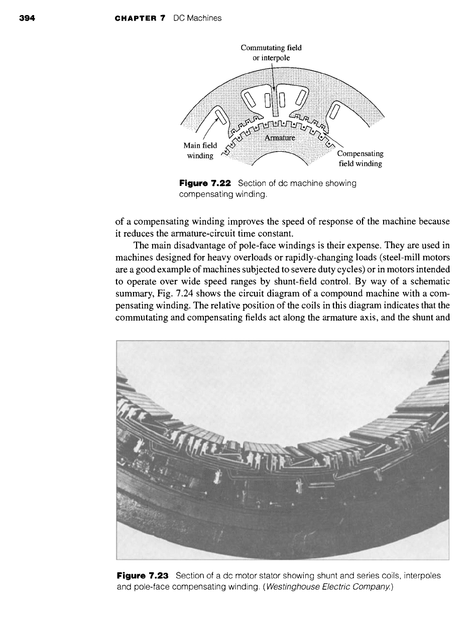
Figure 7.22 Section of dc machine showing
compensating winding.
of a compensating winding improves the speed of response of the machine because
it reduces the armature-circuit time constant.
The main disadvantage of pole-face windings is their expense. They are used in
machines designed for heavy overloads or rapidly-changing loads (steel-mill motors
are a good example of machines subjected to severe duty cycles) or in motors intended
to operate over wide speed ranges by shunt-field control. By way of a schematic
summary, Fig. 7.24 shows the circuit diagram of a compound machine with a com-
pensating winding. The relative position of the coils in this diagram indicates that the
commutating and compensating fields act along the armature axis, and the shunt and
:~:i:, :ii~iiiii~!ii::i~i;ii~;i!ii ~ ,hi~i~i:i~i:i~!~:i,i~:i~i
:~:ii~? :
~
....... :::iiiiiiiiiiiiiiiiiiiiiiiiiiii
Yi~ii!ii~!iiiiiiililiiiiiiiiiii!~i~:i
:~ii,iiii~iii!i!i!iiG,i:!::,: ~
~:!!i!i~iii~ii!i!~i,~'i! ~I~ ~I:II~!
;~:~,:~::,,:U:::::~,;; L: ~
~ ~:i ~?iiiiii!ii~ i ~ i~:i:~: ,~
~ii!~!i
~!~ii~!~:ilil ~II!?~:
YI,~I ~:' ~(i :~ ,i"
..... ~!!~::i ~ _?~:
Figure 7.23 Section of a dc motor stator showing shunt and series coils, interpoles
and pole-face compensating winding.
(Westinghouse Electric Company.)
7.10 Series Universal Motors 395
o Tshunt
/ field
t_00_0 ,
Field ~
o rheostat ~
&9.L
Series
field
Commutating
winding
( ~ Armature
o Compensating
o winding
Figure 7.24
Schematic connection diagram
of a dc machine.
series fields act along the axis of the main poles. Rather complete control of air-gap
flux around the entire armature periphery is thus achieved.
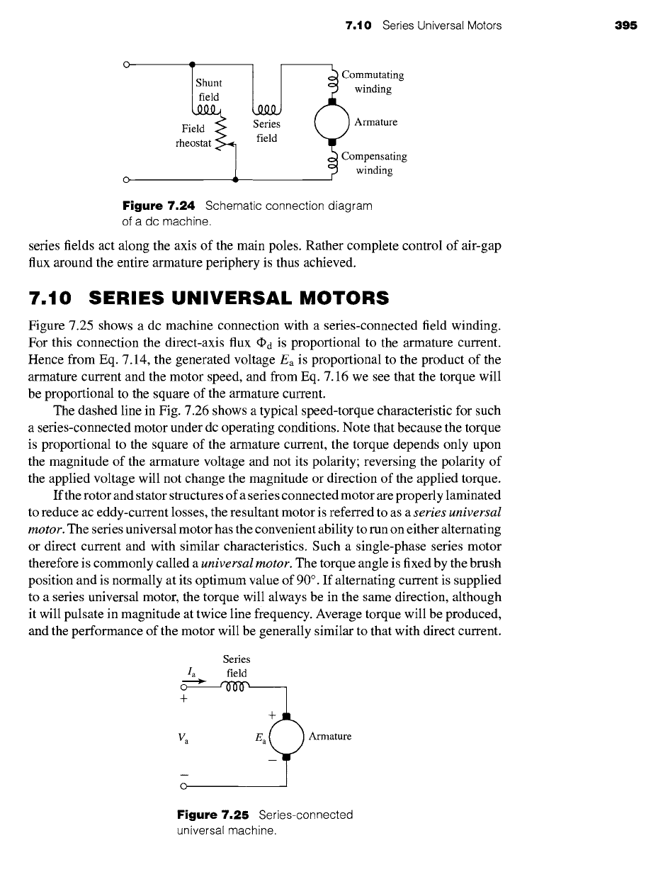
7.10 SERIES UNIVERSAL MOTORS
Figure 7.25 shows a dc machine connection with a series-connected field winding.
For this connection the direct-axis flux @d is proportional to the armature current.
Hence from Eq. 7.14, the generated voltage Ea is proportional to the product of the
armature current and the motor speed, and from Eq. 7.16 we see that the torque will
be proportional to the square of the armature current.
The dashed line in Fig. 7.26 shows a typical speed-torque characteristic for such
a series-connected motor under dc operating conditions. Note that because the torque
is proportional to the square of the armature current, the torque depends only upon
the magnitude of the armature voltage and not its polarity; reversing the polarity of
the applied voltage will not change the magnitude or direction of the applied torque.
If the rotor and stator structures of a series connected motor are properly laminated
to reduce ac eddy-current losses, the resultant motor is referred to as a
series universal
motor.
The series universal motor has the convenient ability to run on either alternating
or direct current and with similar characteristics. Such a single-phase series motor
therefore is commonly called a
universal motor.
The torque angle is fixed by the brush
position and is normally at its optimum value of 90 ° . If alternating current is supplied
to a series universal motor, the torque will always be in the same direction, although
it will pulsate in magnitude at twice line frequency. Average torque will be produced,
and the performance of the motor will be generally similar to that with direct current.
Series
Ia field
>
+
Va Ea
O
Armature
Figure 7.25
Series-connected
universal machine.