Fitzgerald A.E. Electric Machinery
Подождите немного. Документ загружается.

426 CHAPTER 8
Variable-Reluctance Machines and Stepping Motors
continuous at time to = 2.5 msec, and since, from Fig. 8.4 (for 0 ° < 0rn < 60 °)
max )
Lll(0m)
:
El + -~ -~
-- Om
= 0.005 + 0.122(n'/3 - 0m)
Lll(to)il(to)
+ ftt 1)1
dt
o
il(t) =
Lll(t)
0.25 -- 200(t -- 2.5 x 10 -3)
0.005 + 51.1(5 x 10 -3 -- t)
From this equation, we see that the current reaches zero at t -- 3.75 msec.
c. The torque can be found from Eq. 8.9 by setting
i2 =
0. Thus
1
dLll
Tmech
"--
~i~
~m
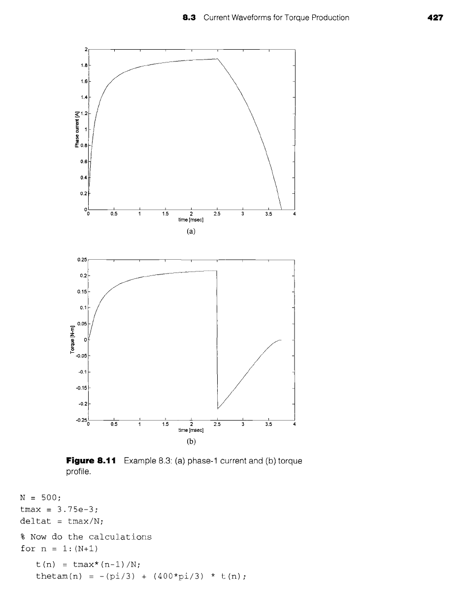
Using MATLAB and the results of parts (a) and (b), the current waveform is plotted
in Fig. 8.1 la and the torque in Fig. 8.1lb. The integral under the torque curve is 3.35 ×
10 -4
N. m. sec while that under the positive portion of the torque curve corresponding to
positive torque is 4.56 x 10 -4 N. m. sec. Thus we see that the negative torque produces a 27
percent reduction in average torque from that which would otherwise be available if the current
could be reduced instantaneously to zero.
Notice first from the results of part (b) and from Fig. 8.11a that, in spite of applying a
negative voltage of twice the magnitude of the voltage used to build up the current, current con-
tinues to flow in the winding for 1.25 ms after reversal of the applied voltage. From Fig. 8.1 lb,
we see that the result is a significant period of negative torque production. In practice, this may,
for example, dictate a control scheme which reverses the phase current in advance of the time
that the sign of
dL(Om)/dOm
reverses, achieving a larger average torque by trading off some
reduction in average positive torque against a larger decrease in average negative torque.
This example also illustrates another important aspect of VRM operation. For a system
of resistance of 1.5 ~ and constant inductance, one would expect a steady-state current of
100/1.5 = 66.7 A. Yet in this system the steady-state current is less than 2 A. The reason for
this is evident from Eqs. 8.14 and 8.15 where we see that
dLll(Om)/dt
= 51.1 ~ appears as an
apparent resistance in series with the winding resistance which is much larger than the winding
resistance itself. The corresponding voltage drop (the speed voltage) is of sufficient magnitude
to limit the steady-state current to a value of 100/51.1 - 1.96 A.
Here is the MATLAB script:
clc
clear
% Here are the inductances
Lmax = 0.128;
Lleak = 0.005;
Posintegral = 0;
integral = 0 ;
we see that the solution becomes
8.3 Current Waveforms for Torque Production 427
~.1.2
i0.8
0.6
0.4
~~ -
_
_
/
I
time [mseel
(a)
0.25
0.15
0.1
0.05
T
z
I--
-0.05
-0.1
-0.15
-0.2
J i i i i i
fJ
215 ~ 315
I i
-°.%
& ~ ~:~ ~
time [msec]
(b)
Figure 8.11 Example 8.3 (a)
phase-1 current and (b) torque
profile.
N = 500 ;
tmax = 3.75e-3;
deltat = tmax/N;
% Now do the calculations
for n = i: (N+I)
t(n) : tmax*(n-1)/N;
thetam(n) =-(pi/3) + (400"pi/3) * t(n);
428 CHAPTER 8 Variable-Reluctance Machines and Stepping Motors
if (thetam(n) <: 0)
i(n) : 100*t(n) / (0.005 + 51.1 *t(n) ) ;
dldlldtheta = 0.122;
Torque(n) = 0.5*i(n)^2*dldlldtheta;
Posintegral = Posintegral + Torque(n)*deltat;
integral = Posintegral;
else
i(n) = (0.25- 200*(t(n) - 2.5e-3))/(0.005+51.I* (5e-3 - t(n)));
dldlldtheta = -0.122;
Torque(n) = 0.5*i(n)^2*dldlldtheta;
integral = integral + Torque(n)*deltat;
end
end
fprintf('\nPositive torque integral = %g [N-m-sec] ',Posintegral)
fprintf('\nTorque integral : %g [N-m-sec]\n',integral)
plot (t*1000, i)
xlabel('time [msec] ')
ylabel('Phase current [A] ')
pause
plot (t*1000, Torque)
xlabel('time [msec] ')
ylabel('Torque [N-m] ')
Reconsider Example 8.3 under the condition that a voltage of -250 V is applied to turn off the
phase current. Use MATLAB to calculate the integral under the torque-versus-time plot and
compare it to the integral under the torque-versus-time curve for the time period during which
the torque is positive.
Solution
The current returns to zero at t = 3.5 msec. The integral under the torque curve is 3.67 ×
10
-4 N. m. s while that under the positive portion of the torque curve corresponding to positive
torque remains equal to 4.56 x 10 -4 N. m. s. In this case, the negative torque produces a
20 percent reduction in torque from that which would otherwise be available if the current
could be reduced instantaneously to zero.
Example 8.3 illustrates important aspects of VRM performance which do not
appear in an idealized analysis such as that of Example 8.1 but which play an extremely
important role in practical applications. It is clear that it is not possible to readily
apply phase currents of arbitrary waveshapes. Winding inductances (and their time
8.3
Current Waveforms for Torque Production 429
derivatives) significantly affect the current waveforms that can be achieved for a given
applied voltage.
In general, the problem becomes more severe as the rotor speed is increased.
Consideration of Example 8.3 shows, for a given applied voltage, (1) that as the
speed is increased, the current will take a larger fraction of the available time during
which
dL(Om)/dOm
is positive to achieve a given level and (2) that the steady-state
current which can be achieved is progressively lowered. One common method for
maximizing the available torque is to apply the phase voltage somewhat in advance
of the time when
dL(Om)/dOm
begins to increase. This gives the current time to build
up to a significant level before torque production begins.
Yet a more significant difficulty (also illustrated in Example 8.3) is that just as the
currents require a significant amount of time to increase at the beginning of a turn-on
cycle, they also require time to decrease at the end. As a result, if the phase excitation
is removed at or near the end of the positive
dL
(0m)/dOm period, it is highly likely that
there will be phase current remaining as
dL(Om)/dOm
becomes negative, so there will
be a period of negative torque production, reducing the effective torque-producing
capability of the VRM.
One way to avoid such negative torque production would be to turn off the phase
excitation sufficiently early in the cycle that the current will have decayed essentially
to zero by the time that
dL(Om)/dOm
becomes negative. However, there is clearly a
point of diminishing returns, because turning off the phase current while dL (0m)/dOm
is positive also reduces positive torque production. As a result, it is often necessary
to accept a certain amount of negative torque (to get the required positive torque)
and to compensate for it by the production of additional positive torque from another
phase.
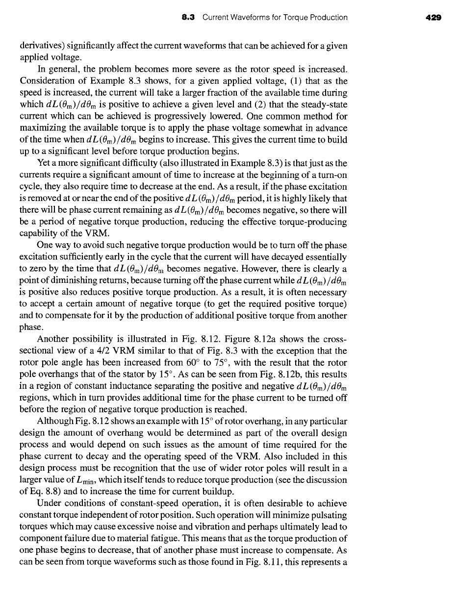
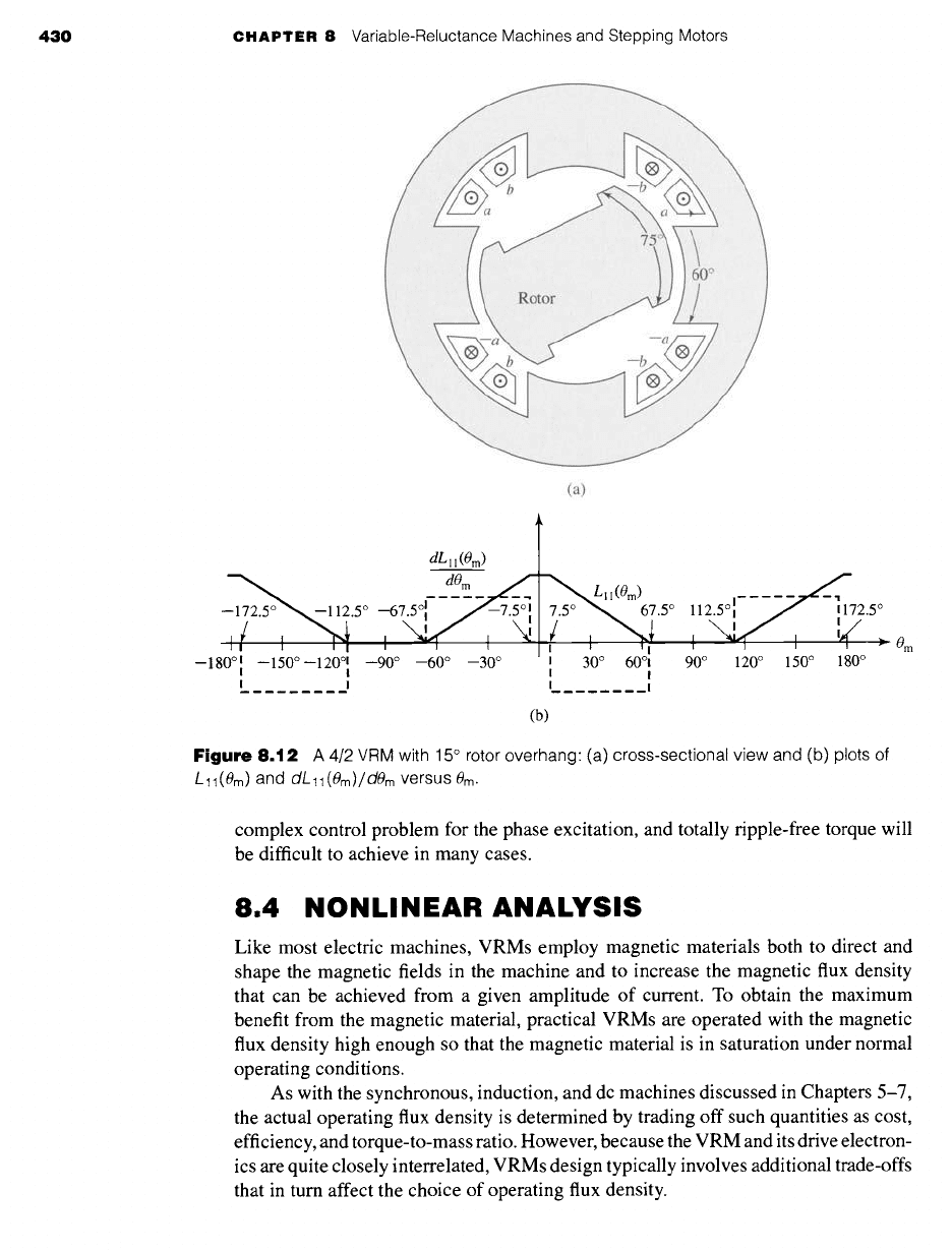
Another possibility is illustrated in Fig. 8.12. Figure 8.12a shows the cross-
sectional view of a 4/2 VRM similar to that of Fig. 8.3 with the exception that the
rotor pole angle has been increased from 60 ° to 75 °, with the result that the rotor
pole overhangs that of the stator by 15 °. As can be seen from Fig. 8.12b, this results
in a region of constant inductance separating the positive and negative
dL(Om)/dOm
regions, which in turn provides additional time for the phase current to be turned off
before the region of negative torque production is reached.
Although Fig. 8.12 shows an example with 15 ° of rotor overhang, in any particular
design the amount of overhang would be determined as part of the overall design
process and would depend on such issues as the amount of time required for the
phase current to decay and the operating speed of the VRM. Also included in this
design process must be recognition that the use of wider rotor poles will result in a
larger value of
Lmin,
which itself tends to reduce torque production (see the discussion
of Eq. 8.8) and to increase the time for current buildup.
Under conditions of constant-speed operation, it is often desirable to achieve
constant torque independent of rotor position. Such operation will minimize pulsating
torques which may cause excessive noise and vibration and perhaps ultimately lead to
component failure due to material fatigue. This means that as the torque production of
one phase begins to decrease, that of another phase must increase to compensate. As
can be seen from torque waveforms such as those found in Fig. 8.11, this represents a
430 CHAPTER 8 Variable-Reluctance Machines and Stepping Motors
(a)
dtll(Om)
dO m
__~_112.5 ° 5/-~---~---~I"--, I ~ Lll(0m) 1
~-67~--7"q [; "5° ~~ "5° 12.5° :- - - - --,7~- ~ 172.5 °
't '~1 , , , ', NN~ :
:# ~--- 0m
--180 °: --150 ° --120 °l --90 ° --60 ° --30 ° I 30 ° 60°1 90 ° 120 ° 150 ° 180 °
I I I
I I I I
(b)
Figure
8.12 A 4/2 VRM with 15 ° rotor overhang: (a) cross-sectional view and (b) plots of
L 11 (#m) and
dL
11 (8m) / dern versus #rn.
complex control problem for the phase excitation, and totally ripple-free torque will
be difficult to achieve in many cases.
8.4 NONLINEAR ANALYSIS
Like most electric machines, VRMs employ magnetic materials both to direct and
shape the magnetic fields in the machine and to increase the magnetic flux density
that can be achieved from a given amplitude of current. To obtain the maximum
benefit from the magnetic material, practical VRMs are operated with the magnetic
flux density high enough so that the magnetic material is in saturation under normal
operating conditions.
As with the synchronous, induction, and dc machines discussed in Chapters 5-7,
the actual operating flux density is determined by trading off such quantities as cost,
efficiency, and torque-to-mass ratio. However, because the VRM and its drive electron-
ics are quite closely interrelated, VRMs design typically involves additional trade-offs
that in turn affect the choice of operating flux density.
8.4 Nonlinear Analysis 431
Om
0 ° 10 ° 20 °
30 °
40 °
50 °
60 °
70 °
80 °
90 °
Phase current, i
0 m
0 o
~10 °
• < _ ~~20 o
°,.~
"~ 50°
60°
!
I I I I I I I
.-
Phase current, i
(a) (b)
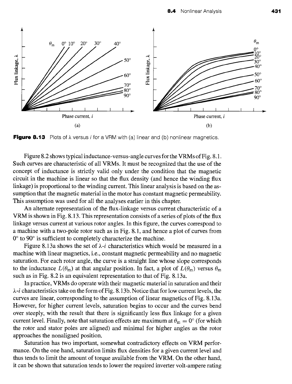
Figure 8.13 Plots of ~. versus i for a VRM with (a)linear and (b) nonlinear magnetics.
Figure 8.2 shows typical inductance-versus-angle curves for the VRMs of Fig. 8.1.
Such curves are characteristic of all VRMs. It must be recognized that the use of the
concept of inductance is strictly valid only under the condition that the magnetic
circuit in the machine is linear so that the flux density (and hence the winding flux
linkage) is proportional to the winding current. This linear analysis is based on the as-
sumption that the magnetic material in the motor has constant magnetic permeability.
This assumption was used for all the analyses earlier in this chapter.
An alternate representation of the flux-linkage versus current characteristic of a
VRM is shown in Fig. 8.13. This representation consists of a series of plots of the flux
linkage versus current at various rotor angles. In this figure, the curves correspond to
a machine with a two-pole rotor such as in Fig. 8.1, and hence a plot of curves from
0 ° to 90 ° is sufficient to completely characterize the machine.
Figure 8.13a shows the set of ~.-i characteristics which would be measured in a
machine with linear magnetics, i.e., constant magnetic permeability and no magnetic
saturation. For each rotor angle, the curve is a straight line whose slope corresponds
to the inductance L(0m) at that angular position. In fact, a plot of L(0m) versus 0m
such as in Fig. 8.2 is an equivalent representation to that of Fig. 8.13a.
In practice, VRMs do operate with their magnetic material in saturation and their
~.-i characteristics take on the form of Fig. 8.13b. Notice that for low current levels, the
curves are linear, corresponding to the assumption of linear magnetics of Fig. 8.13a.
However, for higher current levels, saturation begins to occur and the curves bend
over steeply, with the result that there is significantly less flux linkage for a given
current level. Finally, note that saturation effects are maximum at 0m = 0 ° (for which
the rotor and stator poles are aligned) and minimal for higher angles as the rotor
approaches the nonaligned position.
Saturation has two important, somewhat contradictory effects on VRM perfor-
mance. On the one hand, saturation limits flux densities for a given current level and
thus tends to limit the amount of torque available from the VRM. On the other hand,
it can be shown that saturation tends to lower the required inverter volt-ampere rating
X
~max
0
432 CHAPTER 8 Variable-Reluctance Machines and Stepping Motors
0 m: 0 o
~'max
0 m : 90 °
to i
Om--O °
Om
900
I
0 I 0 i
(a) (b)
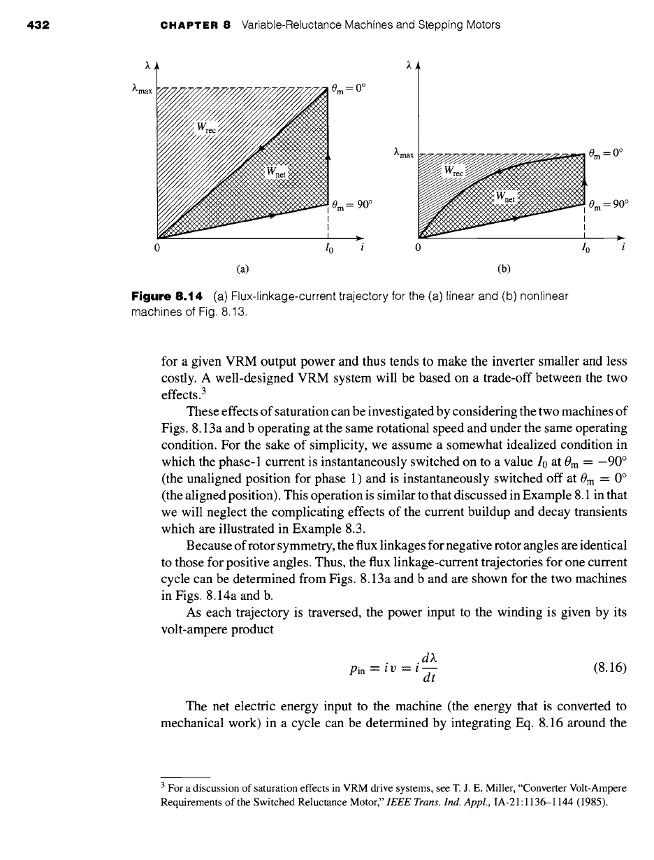
Figure
8.14 (a) Flux-linkage-current trajectory for the (a) linear and (b) nonlinear
machines of Fig. 8.13.
for a given VRM output power and thus tends to make the inverter smaller and less
costly. A well-designed VRM system will be based on a trade-off between the two
effects. 3
These effects of saturation can be investigated by considering the two machines of
Figs. 8.13a and b operating at the same rotational speed and under the same operating
condition. For the sake of simplicity, we assume a somewhat idealized condition in
which the phase-1 current is instantaneously switched on to a value I0 at 0m = -90 °
(the unaligned position for phase 1) and is instantaneously switched off at 0m = 0 °
(the aligned position). This operation is similar to that discussed in Example 8.1 in that
we will neglect the complicating effects of the current buildup and decay transients
which are illustrated in Example 8.3.
Because of rotor symmetry, the flux linkages for negative rotor angles are identical
to those for positive angles. Thus, the flux linkage-current trajectories for one current
cycle can be determined from Figs. 8.13a and b and are shown for the two machines
in Figs. 8.14a and b.
As each trajectory is traversed, the power input to the winding is given by its
volt-ampere product
.d)~
Pin --
i v = t ~ (8.16)
dt
The net electric energy input to the machine (the energy that is converted to
mechanical work) in a cycle can be determined by integrating Eq. 8.16 around the
3 For a discussion of saturation effects in VRM drive systems, see T. J. E. Miller, "Converter Volt-Ampere
Requirements of the Switched Reluctance Motor," IEEE Trans. Ind. Appl., IA-21:1136-1144 (1985).
8,4 Nonlinear Analysis 433
trajectory
Net work - / Pin dt = f i dX
(8.17)
This can be seen graphically as the area enclosed by the trajectory, labeled
Wnet
in
Figs. 8.14a and b. Note that the saturated machine converts less useful work per cycle
than the unsaturated machine. As a result, to get a machine of the same power output,
the saturated machine will have to be larger than a corresponding (hypothetical)
unsaturated machine. This analysis demonstrates the effects of saturation in lowering
torque and power output.
The peak energy input to the winding from the inverter can also be calculated. It
is equal to the integral of the input power from the start of the trajectory to the point
(I0,)~max):
f
~,max
Peak energy = i d)~ (8.18)
J0
This is the total area under the )~-i curve, shown in Fig. 8.14a and b as the sum of the
areas labeled Wrec and
Wnet.
Since we have seen that the energy represented by the
area Wnet
corresponds to
useful output energy, it is clear that the energy represented by the area Wrec corresponds
to energy input that is required to make the VRM operate (i.e., it goes into creating
the magnetic fields in the VRM). This energy produced no useful work; rather it must
be recycled back into the inverter at the end of the trajectory.
The inverter volt-ampere rating is determined by the average power per phase
processed by the inverter as the motor operates, equal to the peak energy input to the
VRM divided by the time T between cycles. Similarly, the average output power per
phase of the VRM is given by the net energy input per cycle divided by T. Thus the
ratio of the inverter volt-ampere rating to power output is
Inverter volt-ampere rating area(Wrec -[-
Wnet)
= (8.19)
Net output area area(Wnet)
In general, the inverter volt-ampere rating determines its cost and size. Thus, for
a given power output from a VRM, a smaller ratio of inverter volt-ampere rating to
output power means that the inverter will be both smaller and cheaper. Comparison
of Figs. 8.14a and b shows that this ratio is smaller in the machine which saturates;
the effect of saturation is to lower the amount of energy which must be recycled each
cycle and hence the volt-ampere rating of the inverter required to supply the VRM.
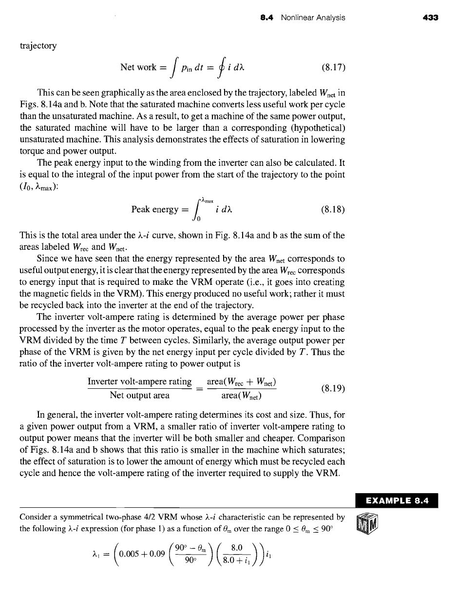
Consider a symmetrical two-phase 4/2 VRM whose X-i characteristic can be represented by
the following )~-i expression (for phase 1) as a function of 0m over the range 0 _< 0m < 90 °
)~1 = 0.005 + 0.09 ~-o 8.0
Jr-
il
434 CHAPTER 8 Variable-Reluctance Machines and Stepping Motors
Phase 2 of this motor is identical to that of phase 1, and there is no significant mutual inductance
between the phases. Assume that the winding resistance is negligible.
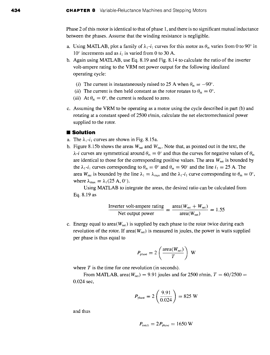
a. Using MATLAB, plot a family of ~-il curves for this motor as 0m varies from 0 to 90 ° in
10 ° increments and as i~ is varied from 0 to 30 A.
b. Again using MATLAB, use Eq. 8.19 and Fig. 8.14 to calculate the ratio of the inverter
volt-ampere rating to the VRM net power output for the following idealized
operating cycle"
(i) The current is instantaneously raised to 25 A when
0 m =
-90 °.
(ii)
The current is then held constant as the rotor rotates to 0m = 0 °.
(iii)
At 0m = 0 °, the current is reduced to zero.
c. Assuming the VRM to be operating as a motor using the cycle described in part (b) and
rotating at a constant speed of 2500 r/min, calculate the net electromechanical power
supplied to the rotor.
II
Solution
a. The
).I-il curves
are shown in Fig. 8.15a.
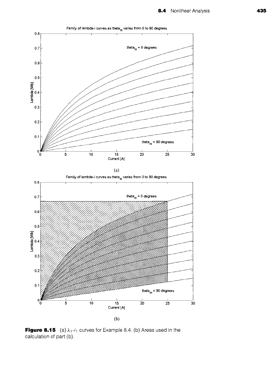
b. Figure 8.15b shows the
areas Wnet
and Wrec. Note that, as pointed out in the text, the
~.-i curves are symmetrical around 0m = 0 ° and thus the curves for negative values of 0rn
are identical to those for the corresponding positive values. The area Wnet is bounded by
the ~.~-i~ curves corresponding to
0 m ---
0 ° and
0 m --
90 '~ and the line
i l =
25 A. The
area Wrec is bounded by the line ~.~
= )~max
and the I.~-i~ curve corresponding to 0m = 0 °,
where ~-m,x = ~.~ (25 A, 0°).
Using MATLAB to integrate the areas, the desired ratio can be calculated from
Eq. 8.19 as
Inverter volt-ampere rating area(Wrec + W, et)
= = 1.55
Net output power
area(Wnet)
c. Energy equal to area(Wnet) is supplied by each phase to the rotor twice during each
revolution of the rotor. If area(Wnet) is measured in joules, the power in watts supplied
per phase is thus equal to
Pphase = 2 (area(Whet) )• T W
where T is the time for one revolution (in seconds).
From MATLAB, area(W.et) = 9.91 joules and for 2500 r/min, T = 60/2500 =
0.024 sec,
9.91)
Pphase ~"
2 = 825 W
0.024
and thus
Breech -'-
2 Pph .... = 1650 W
8.4 Nonlinear Analysis 435
0.8
Family of lambda-i curves as theta m varies from 0 to 90 degrees
i i i i i
0.7
0.6
0.5
___.____ ----~
theta m = 90 degrees
; ,'o
Current [A]
0.8
(a)
Family of lambda-i curves as theta m varies from 0 to 90 degrees
l
1
f
T
0.7
0.6
0.5
.~0.4
0.3
0.2
0.1
-
theta m = 0 degrees
_
= 90
degrees
5 10 15 20 25 30
Current [A]
(b)
Figure 8.15 (a)
A.1-il curves for Example 8.4. (b) Areas used in the
calculation of part (b).