Fitzgerald A.E. Electric Machinery
Подождите немного. Документ загружается.

ct ~ '-0 ~ ~- '-(3 ~ D 0 (I) M M Im '-U ----- CD (1) ~- ~ ~--~ 0 Z 0 !m ..--- ~ 0 ~-- }--'
0 D ~ II 0"] ~ C] 1-~ rt OJ > > I -~- M ~ ~ (1) (1) ~ ('D ~ ~ Z rt ~ D] I -~ O~ ~ ~ ~J (D M ~ (1) (]
!m "~
~- ~- M M ---
w-
o !m 1~ 0 ~ lm ~ ct ~ ~ ~ ~ Q~ (1) Q~ ~- ~ (1) 0 ~ v ~ cr ~ l~
M
:~ 03 c) o (] -. I-- ~ (I) k-, tn ct b( ~ • • !m I/~ C) li k-,- ~ o II k-,
md ~o -. o o <: ~ Z:.' o c~ ~ o ~ (I) li li 0" k,- o -....I ~ Im I= ~ - :~ k--, il ..
"(3 ~ ~ -. ~ m ~ Ln k-' k-' ~
tt
O_, ~ oh - k,- ~ M t-'
tt
~- ..
~:~ ,,i oh ~ '-O ('I) II ti • o M o o 9~ ct -. - k -~ 0-' M ~ Z k-, k-, o 'O
0
~ rr M (I) M I
~- ~- ct M D" ®
0 ~ O_, ~" ~ ~-. c~
-" ~ ~ --~ (I) ~ (I) ~ 0 ~- !m (I) ~ ,-h ~ ~ ...4. ~
(I) (I) "~ ~ ~ \ (I) ~ i ~ O~ []~ --- 0 ~-~ ~~
ct + (I) ~ ~-~ ~ o !EL I ~I ~I ~ ~ 0 o '--4
~0 lm o (I) o ct o (I) Cr ~I 0-' .......
0 ~ > ~ o (I) ~ Lq 0 it ~ 0
"' :~ ~ ~ + "' '-(3 + M tI ~ 0
0 !m (I) • (I)
k ~" <o k~- 0"
I, ~ k-, P-, o t~ ~ o p.~ + P-~
~- (I) <o - Q, q im
(1) x- k ~ ~- n, ,n C~ o ,
o\ ° Ct I--. I ~-
~ ~ Ct ~" "~ ~
• I ~-
0 ~ ~m 0 v ~ ~
_
"-" (I) X • --- • (i) m- ®
..
i Lo -. ~ (D
~-
I--'- "-" Ct
o
i ~- ~.
o ~ el) <o
o3 o
o v v
u3 4- ~h
+ oo
0 ~ 0 O0
• ---4 ~
0 "" 0
k O I-'-
• ~
~"
o
cD v
~ '~ +co
.~. (D
+ M
--- fl)
0
Z
,,,,I
" ID
m"
13.)
O-
l::m :0
(l)
~. 0
o
Im
(]
($]
Im
z]
09
(I)
-'0
-0
"-5
o
0
--.i
8.5 Stepping Motors 437
fprintf('\n\nPart(c) AreaWnet = %g [Joules] ',AreaWnet)
fprintf('\n Pphase : %g [W] and Ptot = %g [W]\n',Pphase,Ptot)
)ractice Problem 8.
Consider a two-phase VRM which is identical to that of Example 8.4 with the exception of
an additional 5 mH of leakage inductance in each phase. (a) Calculate the ratio of the inverter
volt-ampere rating to the VRM net power output for the following idealized operating cycle:
(i) The current is instantaneously raised to 25 A when 0m -- --90 °.
(ii)
The current is then held constant as the rotor rotates to 0m = 10 °.
(iii)
At
0 m =
10 °, the current is reduced to zero.
(b) Assuming the VRM to be operating as a motor using the cycle described in part (a) and
rotating at a constant speed of 2500 r/min, calculate the net electromechanical power supplied
to the rotor.
Solution
b.
emech =
1467 W
Inverter volt-ampere rating
= 1.75
Net output power
Saturation effects clearly play a significant role in the performance of most VRMs
and must be taken into account. In addition, the idealized operating cycle illustrated
in Example 8.4 cannot, of course, be achieved in practice since some rotor motion is
likely to take place over the time scale over which current changes occur. As a result,
it is often necessary to resort to numerical-analysis packages such as finite-element
programs as part of the design process for practical VRM systems. Many of these
programs incorporate the ability to model the nonlinear effects of magnetic saturation
as well as mechanical (e.g., rotor motion) and electrical (e.g., current buildup) dynamic
effects.
As we have seen, the design of a VRM drive system typically requires that a
trade-off be made. On the one hand, saturation tends to increase the size of the VRM
for a given power output. On the other hand, on comparing two VRM systems with
the same power output, the system with the higher level of saturation will typically
require an inverter with a lower volt-ampere rating. Thus the ultimate design will be
determined by a trade-off between the size, cost, and efficiency of the VRM and of
the inverter.
8.5 STEPPING MOTORS
As we have seen, when the phases of a VRM are energized sequentially in an appro-
priate step-wise fashion, the VRM will rotate a specific angle for each step. Motors
designed specifically to take advantage of this characteristic are referred to as
stepping
438 CHAPTER 8 Variable-Reluctance Machines and Stepping Motors
motors
or
stepper motors.
Frequently stepping motors are designed to produce a large
number of steps per revolution, for example 50, 100, or 200 steps per revolution
(corresponding to a rotation of 7.2 °, 3.6 ° and 1.8 ° per step).
An important characteristic of the stepping motor is its compatibility with digital-
electronic systems. These systems are common in a wide variety of applications and
continue to become more powerful and less expensive. For example, the stepping
motor is often used in digital control systems where the motor receives open-loop
commands in the form of a train of pulses to turn a shaft or move an object a specific
distance. Typical applications include paper-feed and print-head-positioning motors in
printers and plotters, drive and head-positioning motors in disk drives and CD players,
and worktable and tool positioning in numerically controlled machining equipment.
In many applications, position information can be obtained simply by keeping count
of the pulses sent to the motor, in which case position sensors and feedback control
are not required.
The angular resolution of a VRM is determined by the number of rotor and stator
teeth and can be greatly enhanced by techniques such as
castleation,
as is discussed in
Section 8.2. Stepping motors come in a wide variety of designs and configurations. In
addition to variable-reluctance configurations, these include permanent-magnet and
hybrid configurations. The use of permanent magnets in combination with a variable-
reluctance geometry can significantly enhance the torque and positional accuracy of
a stepper motor.
The VRM configurations discussed in Sections 8.1 through 8.3 consist of a single
rotor and stator with multiple phases. A stepping motor of this configuration is called
a single-stack, variable-reluctance stepping motor.
An alternate form of variable-
reluctance stepping motor is known as a
multistack variable-reluctance stepping
motor.
In this configuration, the motor can be considered to be made up of a set of
axially displaced, single-phase VRMs mounted on a single shaft.
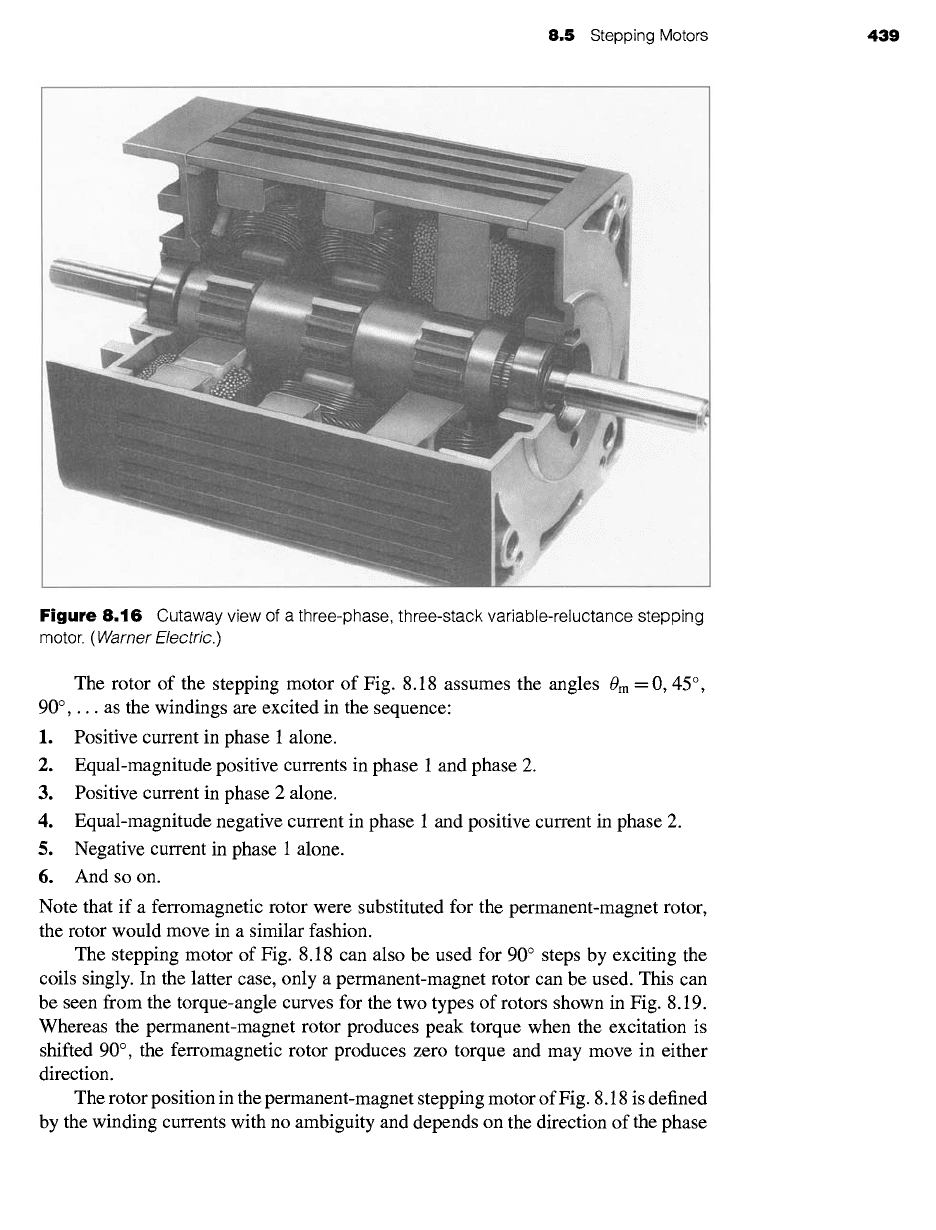
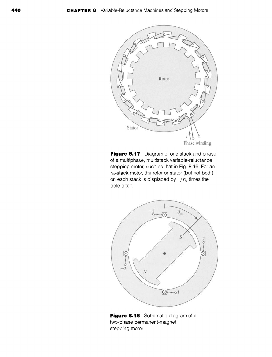
Figure 8.16 shows a multistack variable-reluctance stepping motor. This type of
motor consists of a series of stacks, each axially displaced, of identical geometry and
each excited by a single phase winding, as shown in Fig. 8.17. The motor of Fig. 8.16
has three stacks and three phases, although motors with additional phases and stacks
are common. For an n~-stack motor, the rotor or stator (but not both) on each stack is
displaced by 1 / n~ times the pole-pitch angle. In Fig. 8.16, the rotor poles are aligned,
but the stators are offset in angular displacement by one-third of the pole pitch. By
successively exciting the individual phases, the rotor can be turned in increments of
this displacement angle.
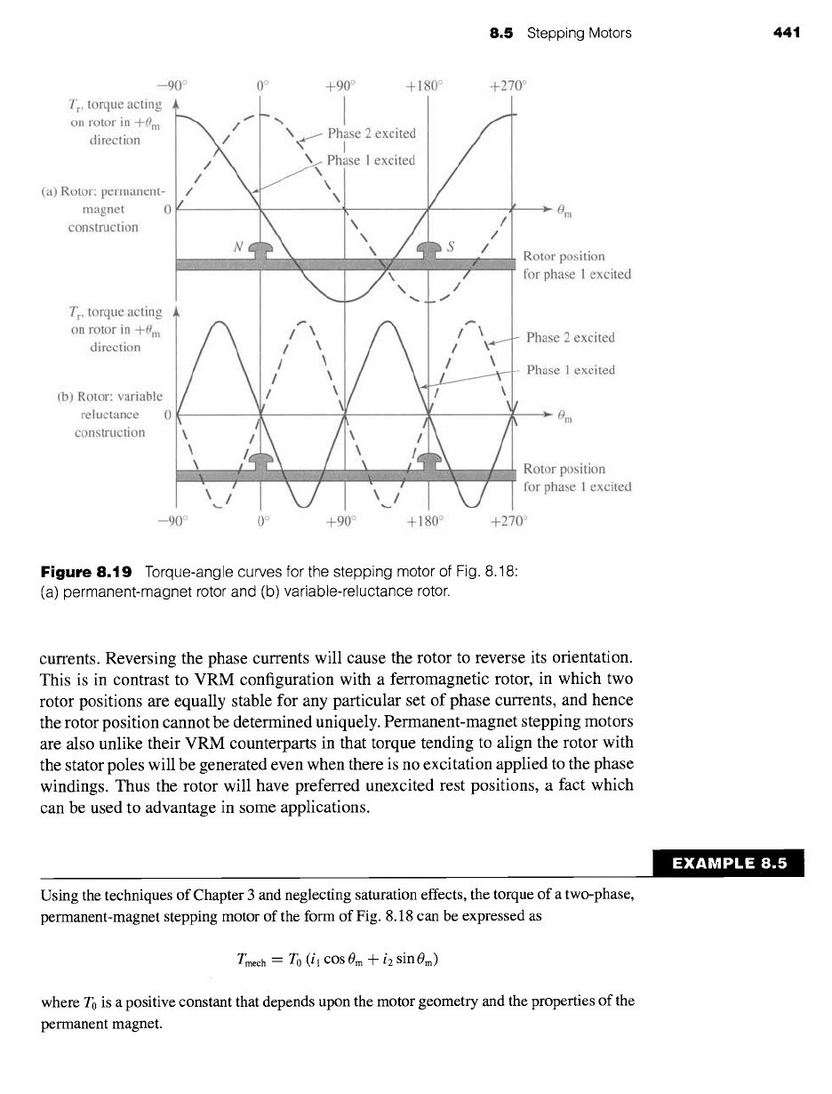
A schematic diagram of a two-phase stepping motor with a permanent-magnet,
two-pole rotor is shown in Fig. 8.18. Note that this machine is in fact a two-phase
synchronous machine, similar for example to the three-phase permanent-magnet
ac machine of Fig. 5.29. The distinction between such a stepping motor and a syn-
chronous motor arises not from the construction of the motor but rather from how the
motor is operated. The synchronous motor is typically intended to drive a load at a
specified speed, and the stepping motor is typically intended to control the position
of a load.
8.5 Stepping Motors 439
Figure 8.16
Cutaway view
of a
three-phase, three-stack variable-reluctance stepping
motor. (
Warner Electric.)
The rotor of the stepping motor of Fig. 8.18 assumes the angles 0m = 0, 45 °,
90°,... as the windings are excited in the sequence:
1. Positive current in phase 1 alone.
2. Equal-magnitude positive currents in phase 1 and phase 2.
3. Positive current in phase 2 alone.
4.
Equal-magnitude negative current in phase 1 and positive current in phase 2.
5. Negative current in phase 1 alone.
6. And so on.
Note that if a ferromagnetic rotor were substituted for the permanent-magnet rotor,
the rotor would move in a similar fashion.
The stepping motor of Fig. 8.18 can also be used for 90 ° steps by exciting the
coils singly. In the latter case, only a permanent-magnet rotor can be used. This can
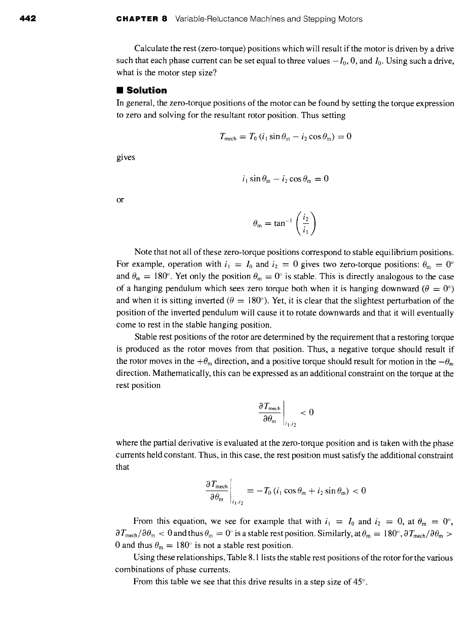
be seen from the torque-angle curves for the two types of rotors shown in Fig. 8.19.
Whereas the permanent-magnet rotor produces peak torque when the excitation is
shifted 90 °, the ferromagnetic rotor produces zero torque and may move in either
direction.
The rotor position in the permanent-magnet stepping motor of Fig. 8.18 is defined
by the winding currents with no ambiguity and depends on the direction of the phase
440 CHAPTER 8 Variable-Reluctance Machines and Stepping Motors
Phase winding
Figure 8.17 Diagram of one stack and phase
of a multiphase, multistack variable-reluctance
stepping motor, such as that in Fig. 8.16. For an
ns-stack motor, the rotor or stator (but not both)
on each stack is displaced by 1/ns times the
pole pitch.
i:!iiiiiii:iiiUiliiiiiiiiJiiiiiii~i~;
i :::~LiiiiiiiTiliiiiiiiiiiiTiiiiiiiiil
1: ¸
Figure 8.18 Schematic diagram of a
two-phase permanent-magnet
stepping motor.
8..5 Stepping Motors 441
--90 °
T r, torque acting
on rotor in +0 m
direction
(a) Rotor: permanent-
magnet 0
construction
T r, torque acting
on rotor in +0 m
direction
(b) Rotor: variable
reluctance
construction
0 °
i1
\~ Phpse 2 excited
P~ase 1 excited
...a ,,,,_,d,
/ \
/ \
/ \
/ \
0
'/
,,
--90 ° 0 o +90 °
+90 ° + 180 ° +270 °
i
~---~ Om
/
!
s / Rotor position
for 1 excited
phase
/ \ Phase 2 excited
~t
/ ~._ Phase 1 excited
'/'0m
Rotor position
for phase 1 excited
+ 180 ° +270 °
Figure
8.19 Torque-angle curves for the stepping motor of Fig. 8.18:
(a) permanent-magnet rotor and (b) variable-reluctance rotor.
currents. Reversing the phase currents will cause the rotor to reverse its orientation.
This is in contrast to VRM configuration with a ferromagnetic rotor, in which two
rotor positions are equally stable for any particular set of phase currents, and hence
the rotor position cannot be determined uniquely. Permanent-magnet stepping motors
are also unlike their VRM counterparts in that torque tending to align the rotor with
the stator poles will be generated even when there is no excitation applied to the phase
windings. Thus the rotor will have preferred unexcited rest positions, a fact which
can be used to advantage in some applications.
Using the techniques of Chapter 3 and neglecting saturation effects, the torque of a two-phase,
permanent-magnet stepping motor of the form of Fig. 8.18 can be expressed as
Tmech : To (il cos 0m n t- i2 sin 0m)
where To is a positive constant that depends upon the motor geometry and the properties of the
permanent magnet.
EXAMPLE 8.5
442 CHAPTER 8 Variable-Reluctance Machines and Stepping Motors
Calculate the rest (zero-torque) positions which will result if the motor is driven by a drive
such that each phase current can be set equal to three values -I0, 0, and I0. Using such a drive,
what is the motor step size?
II Solution
In general, the zero-torque positions of the motor can be found by setting the torque expression
to zero and solving for the resultant rotor position. Thus setting
Tmech --- To
(il sin 0m
- i2 cos 0m) "- 0
gives
i~ sin 0m - i2 cos 0m : 0
or
(i2)
0 m :
tan-~ i-~
Note that not all of these zero-torque positions correspond to stable equilibrium positions.
For example, operation with i~ - I0 and
i2 -
0 gives two zero-torque positions: 0m = 0 °
and 0m = 180 °. Yet only the position 0m = 0 ° is stable. This is directly analogous to the case
of a hanging pendulum which sees zero torque both when it is hanging downward (0 = 0 °)
and when it is sitting inverted (0 -- 180 °). Yet, it is clear that the slightest perturbation of the
position of the inverted pendulum will cause it to rotate downwards and that it will eventually
come to rest in the stable hanging position.
Stable rest positions of the rotor are determined by the requirement that a restoring torque
is produced as the rotor moves from that position. Thus, a negative torque should result if
the rotor moves in the +0m direction, and a positive torque should result for motion in the -0m
direction. Mathematically, this can be expressed as an additional constraint on the torque at the
rest position
OTm~h I
00|n il ,i2
<0
where the partial derivative is evaluated at the zero-torque position and is taken with the phase
currents held constant. Thus, in this case, the rest position must satisfy the additional constraint
that
0 Tmech
00,,
tl ,t2
--- -To (il
COS0m
-']- i2 sin 0m) < 0
From this equation, we see for example that with i~ = I0 and
i2 = 0,
at
0 m = 0 °,
OTmech/OOm < 0and thus0m = 0 ~ isastable rest position. Similarly, at0m = 180 °, OTmech/OOm >
0 and thus 0m --- 180 ~ is not a stable rest position.
Using these relationships, Table 8.1 lists the stable rest positions of the rotor for the various
combinations of phase currents.
From this table we see that this drive results in a step size of 45 °.
8.5
Stepping Motors 443
Table
8.1 Rotor rest positions for Example 8.5.
ii
il i2
0m
0 0
0 -Io 270 °
0 Io 90 °
-Io 0 180 °
-Io -Io 225 °
-Io Io 135 °
Io 0 0 o
Io -Io 315 °
Io I0 45 °
In order to achieve a step size of 22.5 °, the motor drive of Example 8.5 is modified so that each
phase can be driven by currents of magnitude 0,
+klo,
and 4-10. Find the required value of the
constant k.
Solution
k = tan -1 (22.5 °) = 0.4142
In Example 8.5 we see that stable equilibrium positions of an unloaded stepping
motor satisfy the conditions that there is zero torque, i.e.,
Tmech = 0 (8.20)
and that there is positive restoring torque, i.e.,
0Tmech
< 0 (8.21)
OOm il,i2
In practice, there will of course be a finite load torque tending to perturb the stepping
motor from these idealized positions. For open-loop control systems (i.e., control
systems in which there is no mechanism for position feedback), a high-degree of
position control can be achieved by designing the stepping motor to produce large
restoring torque (i.e., a large magnitude of
O Tmech/OOm).
In such a stepping motor,
load torques will result in only a small movement of the rotor from the idealized
positions which satisfies Eqs. 8.20 and 8.21.
Example 8.5 also shows how carefully controlled combinations of phase cur-
rents can enhance the resolution of a stepper motor. This technique, referred to as
microstepping,
can be used to achieve increased step resolution of a wide variety
of stepper motors. As the following example shows, microstepping can be used to
produce extremely fine position resolution. The increased resolution comes, however,
at the expense of an increase in complexity of the stepping-motor drive electronics
and control algorithms, which must accurately control the distribution of current to
multiple phases simultaneously.
444 CHAPTER 8 Variable-Reluctance Machines and Stepping Motors
EXAMPLE 8.6
Consider again the two-phase, permanent-magnet stepping motor of Example 8.5. Calculate
the rotor position which will result if the phase currents are controlled to be sinusoidal functions
of a reference angle 0rer in the form
il
= I0cOS0ref
i2 = I0 sin 0ref
II
Solution
Substitution of the current expressions into the torque expression of Example 8.5 gives
Tmech = To (il COS0m + i2 sin0m) =
Tolo
(cos 0r~rCOS0m + sin0r~f sin0m)
Use of the trigonometric identity cos (ol -/~) = cos ot cos/~ ÷ sin c~ sin ~ gives
Tmech --
Tolo
cos (Ore f -- 0m)
From this expression and using the analysis of Example 8.5, we see that the rotor equilib-
rium position will be equal to the reference angle, i.e., 0m = 0r~f. In a practical implementation,
a digital controller is likely to be used to increment
0re f
in finite steps, which will result in finite
steps in the position of the stepping-motor.
The
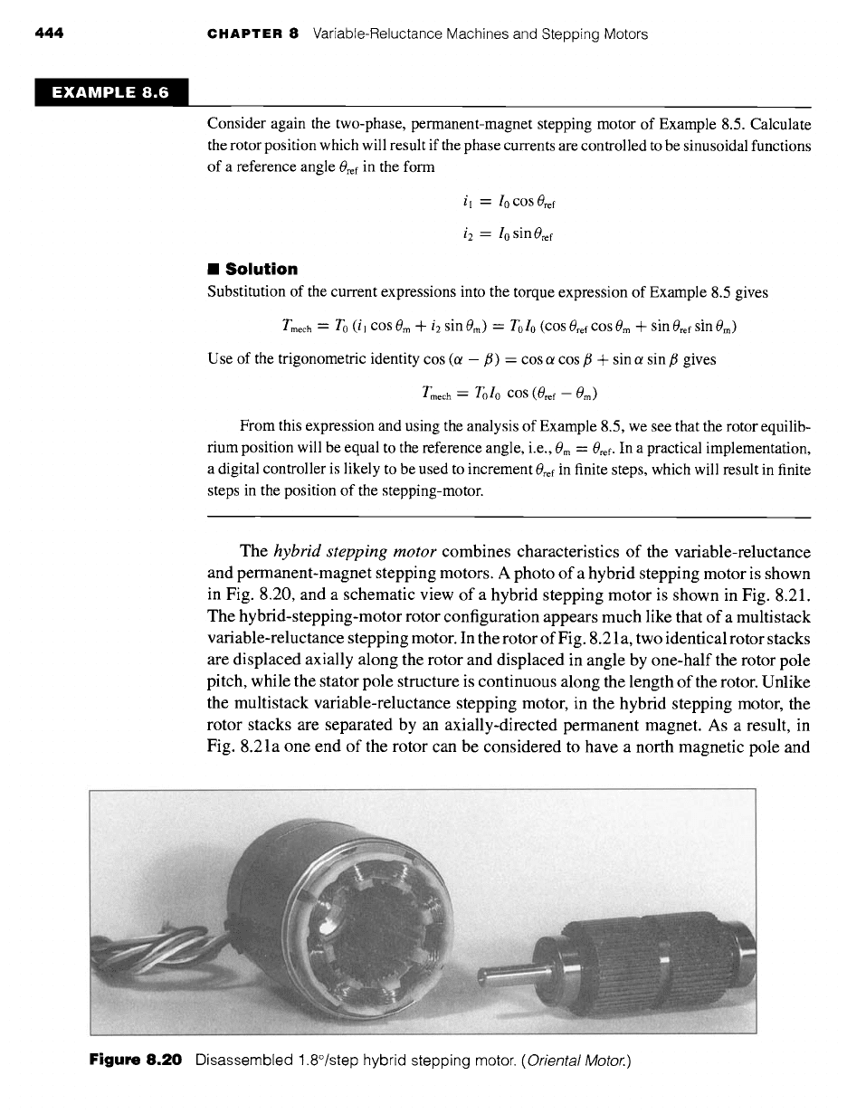
hybrid stepping motor
combines characteristics of the variable-reluctance
and permanent-magnet stepping motors. A photo of a hybrid stepping motor is shown
in Fig. 8.20, and a schematic view of a hybrid stepping motor is shown in Fig. 8.21.
The hybrid-stepping-motor rotor configuration appears much like that of a multistack
variable-reluctance stepping motor. In the rotor of Fig. 8.21 a, two identical rotor stacks
are displaced axially along the rotor and displaced in angle by one-half the rotor pole
pitch, while the stator pole structure is continuous along the length of the rotor. Unlike
the multistack variable-reluctance stepping motor, in the hybrid stepping motor, the
rotor stacks are separated by an axially-directed permanent magnet. As a result, in
Fig. 8.21 a one end of the rotor can be considered to have a north magnetic pole and
i ;:i, ~ : '(::~: !'ili i i liiii!iiiii::: ......
: i i :! i ¸ !!i! ¸¸ I
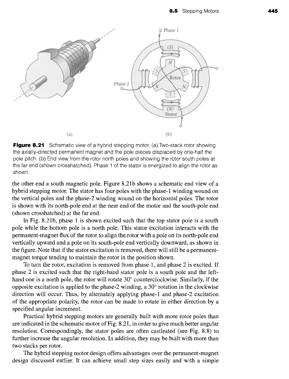
Figure
8.20 Disassembled 1.8°/step hybrid stepping motor.
(Oriental Motor.)
8.5 Stepping Motors 445
f
f
f
f
Phase 1
Phase 2
(a) (b)
Figure
8.21 Schematic view of a hybrid stepping motor. (a) Two-stack rotor showing
the axially-directed permanent magnet and the pole pieces displaced by one-half the
pole pitch. (b) End view from the rotor north poles and showing the rotor south poles at
the far end (shown crosshatched). Phase 1 of the stator is energized to align the rotor as
shown.
the other end a south magnetic pole. Figure 8.2 lb shows a schematic end view of a
hybrid stepping motor. The stator has four poles with the phase-1 winding wound on
the vertical poles and the phase-2 winding wound on the horizontal poles. The rotor
is shown with its north-pole end at the near end of the motor and the south-pole end
(shown crosshatched) at the far end.
In Fig. 8.21b, phase 1 is shown excited such that the top stator pole is a south
pole while the bottom pole is a north pole. This stator excitation interacts with the
permanent-magnet flux of the rotor to align the rotor with a pole on its north-pole end
vertically upward and a pole on its south-pole end vertically downward, as shown in
the figure. Note that if the stator excitation is removed, there will still be a permanent-
magnet torque tending to maintain the rotor in the position shown.
To turn the rotor, excitation is removed from phase 1, and phase 2 is excited. If
phase 2 is excited such that the fight-hand stator pole is a south pole and the left-
hand one is a north pole, the rotor will rotate 30 ° counterclockwise. Similarly, if the
opposite excitation is applied to the phase-2 winding, a 30 ° rotation in the clockwise
direction will occur. Thus, by alternately applying phase-1 and phase-2 excitation
of the appropriate polarity, the rotor can be made to rotate in either direction by a
specified angular increment.
Practical hybrid stepping motors are generally built with more rotor poles than
are indicated in the schematic motor of Fig. 8.21, in order to give much better angular
resolution. Correspondingly, the stator poles are often castleated (see Fig. 8.8) to
further increase the angular resolution. In addition, they may be built with more than
two stacks per rotor.
The hybrid stepping motor design offers advantages over the permanent-magnet
design discussed earlier. It can achieve small step sizes easily and with a simple