Fitzgerald A.E. Electric Machinery
Подождите немного. Документ загружается.

416 CHAPTER 8 Variable-Reluctance Machines and Stepping Motors
As in any engineering situation, the final design for a specific application will involve
a compromise between the variety of options available to the designer. Because VRMs
require some sort of electronics and control to operate, often the designer is concerned
with optimizing a characteristic of the complete drive system, and this will impose
additional constraints on the motor design.
VRMs can be built in a wide variety of configurations. In Fig. 8.1, two forms of
a 4/2 machine are shown: a singly-salient machine in Fig. 8.1a and a doubly-salient
machine in Fig. 8. lb. Although both types of design can be made to work, a doubly-
salient design is often the superior choice because it can generally produce a larger
torque for a given frame size.
This can be seen qualitatively (under the assumption of a high-permeability,
nonsaturating magnetic structure) by reference to Eq. 8.7, which shows that the torque
is a function of dLll (Om)/dOm, the derivative of the phase inductance with respect
to angular position of the rotor. Clearly, all else being equal, the machine with the
largest derivative will produce the largest torque.
This derivative can be thought of as being determined by the ratio of the maximum
to minimum phase inductances
Lmax/Lmin.
In other words, we can write,
dLll
(Om) ,~ Lmax -- Lmin
dOm
A0m
= A0m gmax (8.8)
where A0m is the angular displacement of the rotor between the positions of maximum
and minimum phase inductance. From Eq. 8.8, we see that, for a given Lmax and A0m,
the largest value of
Lmax/Lmin
will give the largest torque. Because of its geometry,
a doubly-salient structure will typically have a lower minimum inductance and thus
a larger value of Lmax/Lmin; hence it will produce a larger torque for the same rotor
structure.
For this reason doubly-salient machines are the predominant type of VRM, and
hence for the remainder of this chapter we consider only doubly-salient VRMs. In
general, doubly-salient machines can be constructed with two or more poles on each
of the stator and rotor. It should be pointed out that once the basic structure of a
VRM is determined,
Lmax
is fairly well determined by such quantities as the num-
ber of turns, air-gap length, and basic pole dimensions. The challenge to the VRM
designer is to achieve a small value of
Lmi n.
This is a difficult task because
Lmin
is
dominated by leakage fluxes and other quantities which are difficult to calculate and
analyze.
As shown in Example 8.1, the geometry of a symmetric 4/2 VRM with a uniform
air gap gives rise to rotor positions for which no torque can be developed for any
combination of excitation of the phase windings. These torque zeros can be seen to
occur at rotor positions where all the stator phases are simultaneously at a position of
either maximum or minimum inductance. Since the torque depends on the derivative of
inductance with respect to angular position, this simultaneous alignment of maximum
and minimum inductance points necessarily results in zero net torque.
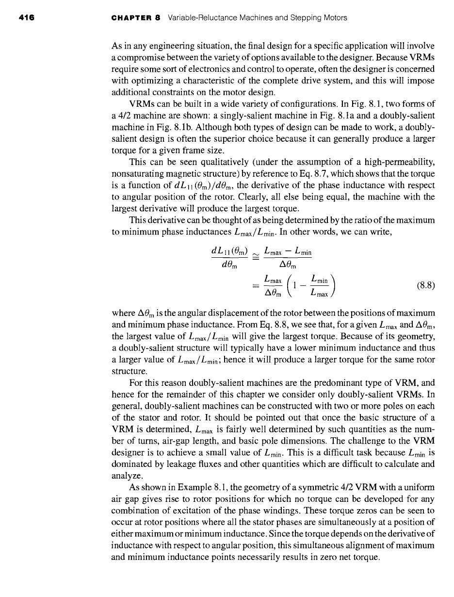
8.2 Practical VRM Configurations 417
Phase
1
ol
--3
--2
r b2
Phase 2
3o-.
Phase 3
-1
Figure
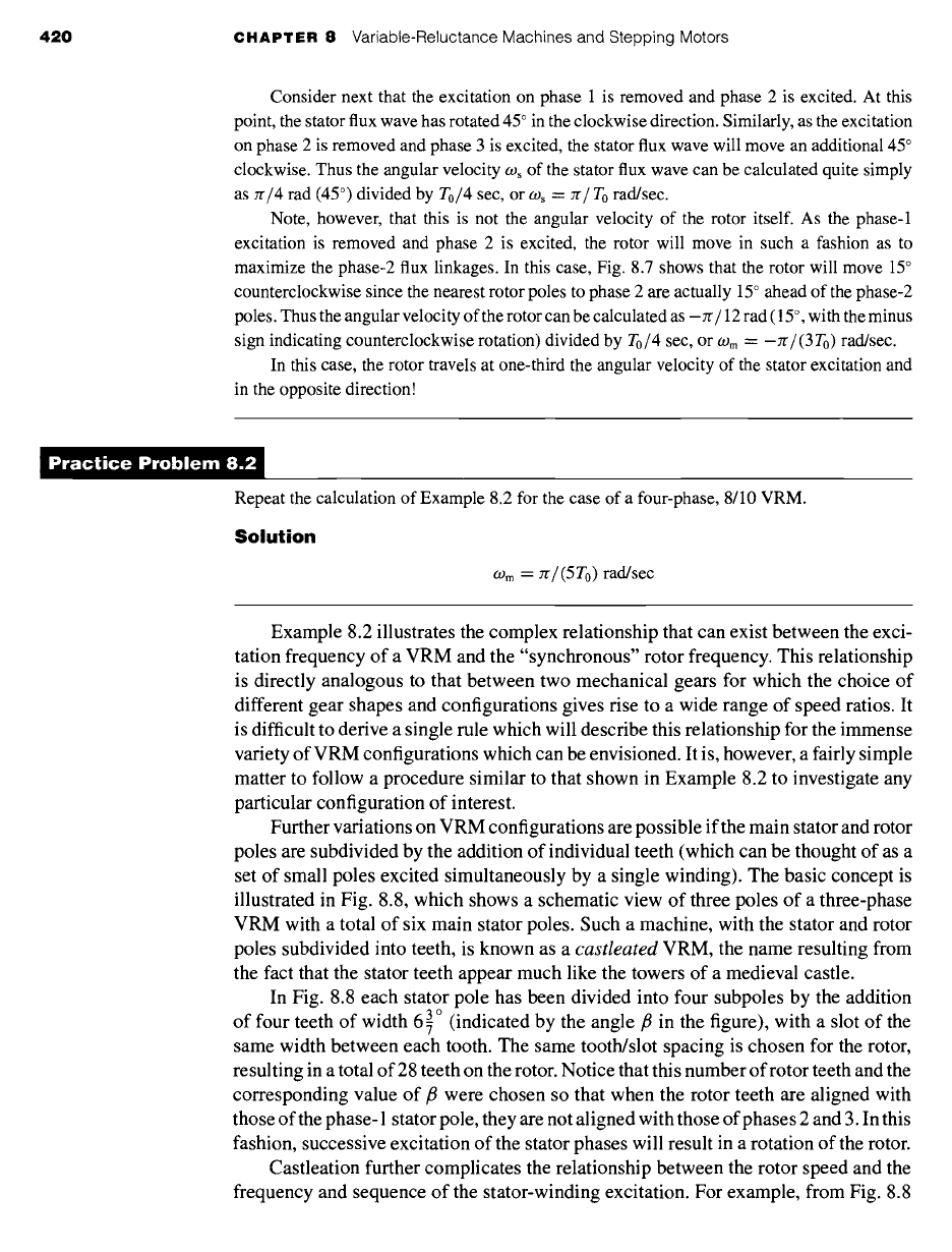
8.5 Cross-sectional view of a 6/4 three-phase VRM.
Figure 8.5 shows a 6/4 VRM from which we see that a fundamental feature
of the 6/4 machine is that no such simultaneous alignment of phase inductances is
possible. As a result, this machine does not have any zero-torque positions. This is a
significant point because it eliminates the possibility that the rotor might get stuck in
one of these positions at standstill, requiring that it be mechanically moved to a new
position before it can be started. In addition to the fact that there are not positions of
simultaneous alignment for the 6/4 VRM, it can be seen that there also are no rotor
positions at which only a torque of a single sign (either positive or negative) can be
produced. Hence by proper control of the phase currents, it should be possible to
achieve constant-torque, independent of rotor position.
In the case of a symmetric VRM with Ps stator poles and Pr rotor poles, a
simple test can be used to determine if zero-torque positions exist. If the ratio
Ps/Pr
(or alternatively
Pr/Ps
if Pr is larger than Ps) is an integer, there will be zero-torque
positions. For example, for a 6/4 machine the ratio is 1.5, and there will be no zero-
torque positions. However, the ratio is 2.0 for a 6/3 machine, and there will be zero-
torque positions.
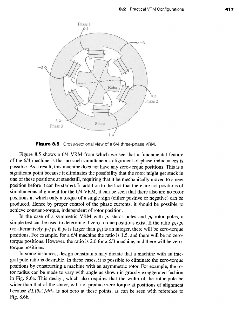
In some instances, design constraints may dictate that a machine with an inte-
gral pole ratio is desirable. In these cases, it is possible to eliminate the zero-torque
positions by constructing a machine with an asymmetric rotor. For example, the ro-
tor radius can be made to vary with angle as shown in grossly exaggerated fashion
in Fig. 8.6a. This design, which also requires that the width of the rotor pole be
wider than that of the stator, will not produce zero torque at positions of alignment
because
dL(Om)/dOm
is not zero at these points, as can be seen with reference to
Fig. 8.6b.
418 CHAPTER 8 Variable-Reluctance Machines and Stepping Motors
(a)
I l .. s I
--7l" I I I /
I I I I
I I I I
Ii
/
d L ( O m ) II I I
~...I
dO m
~..t
0 m
(b)
Figure
8.6 A 4/2 VRM with nonuniform air gap: (a) exaggerated
schematic view and (b) plots of L(0m) and
dL(Om)/dOm
versus 0m.
An alternative procedure for constructing an integral-pole-ratio VRM without
zero-torque positions is to construct a stack of two or more VRMs in series, aligned
such that each of the VRMs is displaced in angle from the others and with all rotors
sharing a common shaft. In this fashion, the zero-torque positions of the individual
machines will not align, and thus the complete machine will not have any torque zeros.
For example, a series stack of two two-phase, 4/2 VRMs such as that of Example 8.1
(Fig. 8.3) with a 45 ° angular displacement between the individual VRMs will result
in a four-phase VRM without zero-torque positions.
Generally VRMs are wound with a single coil on each pole. Although it is possible
to control each of these windings separately as individual phases, it is common practice
to combine them into groups of poles which are excited simultaneously. For example,
the 4/2 VRM of Fig. 8.3 is shown connected as a two-phase machine. As shown in
Fig. 8.5, a 6/4 VRM is commonly connected as a three-phase machine with opposite
poles connected to the same phase and in such a fashion that the windings drive flux
in the same direction through the rotor.
8.2 Practical VRM Configurations 419
In some cases, VRMs are wound with a parallel set of windings on each phase.
This configuration, known as a
bifilar winding,
in some cases can result in a simple
inverter configuration and thus a simple, inexpensive motor drive. The use of a bifilar
winding in VRM drives is discussed in Section 11.4.
In general, when a given phase is excited, the torque is such that the rotor is
pulled to the nearest position of maximum flux linkage. As excitation is removed
from that phase and the next phase is excited, the rotor "follows" as it is then pulled
to a new maximum flux-linkage position. Thus, the rotor speed is determined by the
frequency of the phase currents. However, unlike the case of a synchronous machine,
the relationship between the rotor speed and the frequency and sequence of the phase-
winding excitation can be quite complex, depending on the number of rotor poles and
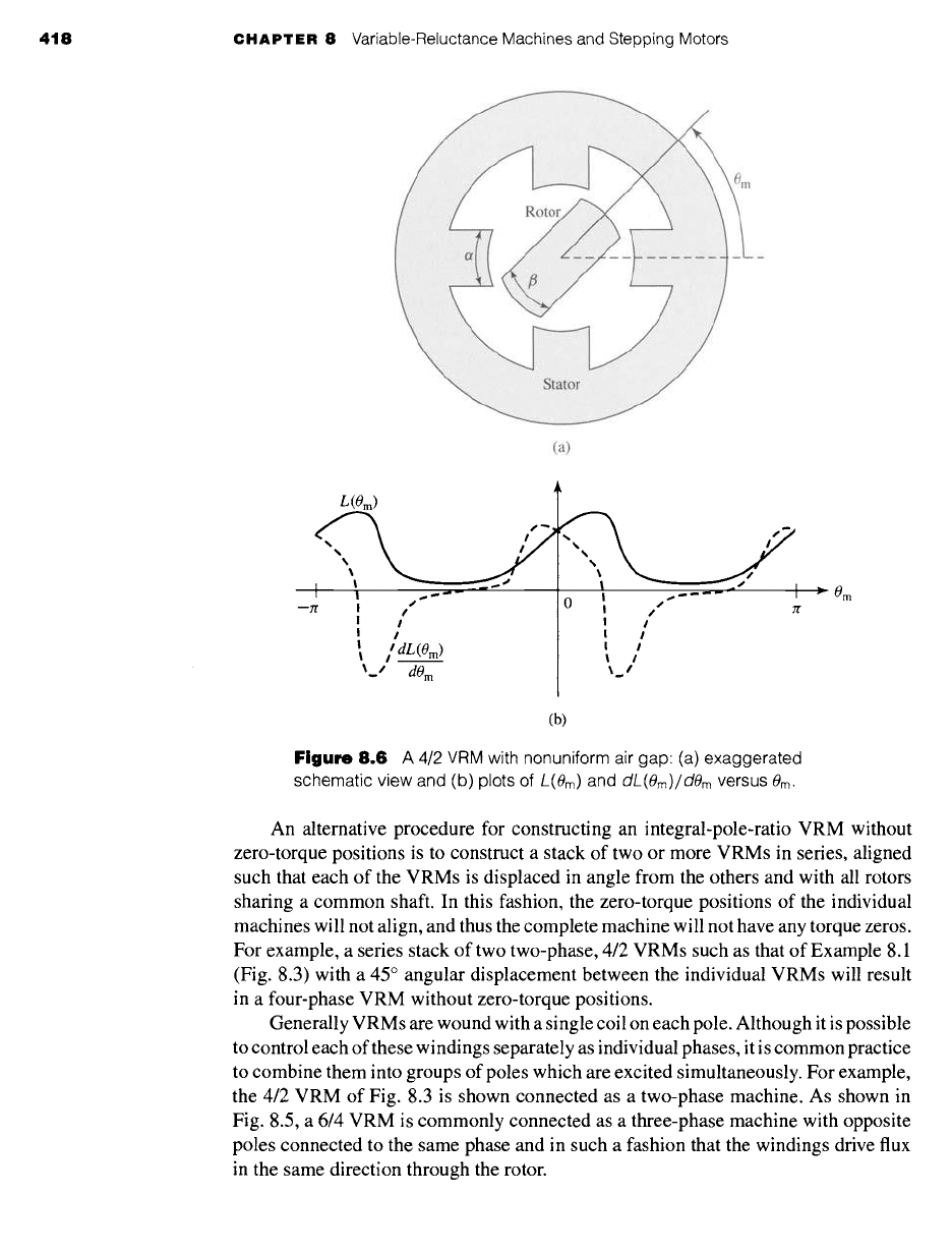
the number of stator poles and phases. This is illustrated in Example 8.2.
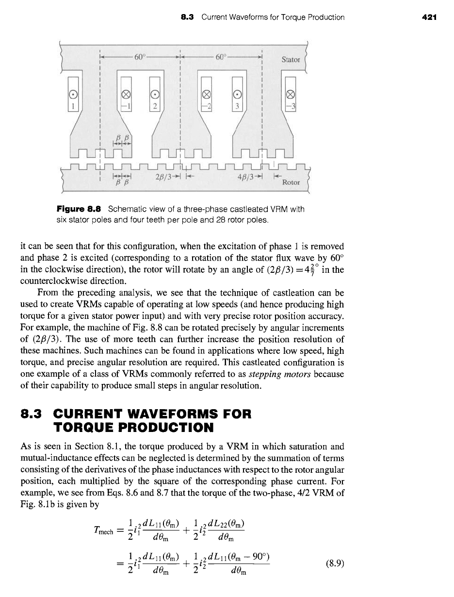
Consider a four-phase, 8/6 VRM. If the stator phases are excited sequentially, with a total time
of To sec required to excite the four phases (i.e., each phase is excited for a time of
To~4
sec),
find the angular velocity of the stator flux wave and the corresponding angular velocity of the
rotor. Neglect any system dynamics and assume that the rotor will instantaneously track the
stator excitation.
II Solution
Figure 8.7 shows in schematic form an 8/6 VRM. The details of the pole shapes are not of
importance for this example and thus the rotor and stator poles are shown simply as arrows
indicating their locations. The figure shows the rotor aligned with the stator phase-1 poles.
This position corresponds to that which would occur if there were no load on the rotor and the
stator phase-1 windings were excited, since it corresponds to a position of maximum phase-1
flux linkage.
EXAMPLE 8.2
Figure
8.7 Schematic view of a
four-phase 8/6 VRM. Pole locations
are indicated by arrows.
420
CHAPTER 8 Variable-Reluctance Machines and Stepping Motors
Consider next that the excitation on phase 1 is removed and phase 2 is excited. At this
point, the stator flux wave has rotated 45 ° in the clockwise direction. Similarly, as the excitation
on phase 2 is removed and phase 3 is excited, the stator flux wave will move an additional 45 °
clockwise. Thus the angular velocity Ogs of the stator flux wave can be calculated quite simply
as zr/4 rad (45 °) divided by To~4 sec, or w~ = re/To rad/sec.
Note, however, that this is not the angular velocity of the rotor itself. As the phase-1
excitation is removed and phase 2 is excited, the rotor will move in such a fashion as to
maximize the phase-2 flux linkages. In this case, Fig. 8.7 shows that the rotor will move 15 °
counterclockwise since the nearest rotor poles to phase 2 are actually 15 ° ahead of the phase-2
poles. Thus the angular velocity of the rotor can be calculated as -Jr/12 rad (15 °, with the minus
sign indicating counterclockwise rotation) divided by To~4 see, or
09 m =
-zr/(3T0) rad/sec.
In this case, the rotor travels at one-third the angular velocity of the stator excitation and
in the opposite direction!
)ractice Problem 8.:
Repeat the calculation of Example 8.2 for the case of a four-phase, 8/10 VRM.
Solution
09 m "-- n / (5 T 0)
rad/sec
Example 8.2 illustrates the complex relationship that can exist between the exci-
tation frequency of a VRM and the "synchronous" rotor frequency. This relationship
is directly analogous to that between two mechanical gears for which the choice of
different gear shapes and configurations gives rise to a wide range of speed ratios. It
is difficult to derive a single rule which will describe this relationship for the immense
variety of VRM configurations which can be envisioned. It is, however, a fairly simple
matter to follow a procedure similar to that shown in Example 8.2 to investigate any
particular configuration of interest.
Further variations on VRM configurations are possible if the main stator and rotor
poles are subdivided by the addition of individual teeth (which can be thought of as a
set of small poles excited simultaneously by a single winding). The basic concept is
illustrated in Fig. 8.8, which shows a schematic view of three poles of a three-phase
VRM with a total of six main stator poles. Such a machine, with the stator and rotor
poles subdivided into teeth, is known as a castleated VRM, the name resulting from
the fact that the stator teeth appear much like the towers of a medieval castle.
In Fig. 8.8 each stator pole has been divided into four subpoles by the addition
3 o (indicated by the angle/3 in the figure), with a slot of the
of four teeth of width 6 7
same width between each tooth. The same tooth/slot spacing is chosen for the rotor,
resulting in a total of 28 teeth on the rotor. Notice that this number of rotor teeth and the
corresponding value of/3 were chosen so that when the rotor teeth are aligned with
those of the phase- 1 stator pole, they are not aligned with those of phases 2 and 3. In this
fashion, successive excitation of the stator phases will result in a rotation of the rotor.
Castleation further complicates the relationship between the rotor speed and the
frequency and sequence of the stator-winding excitation. For example, from Fig. 8.8
8.3
Current Waveforms for Torque Production 421
I
Figure 8.8
Schematic view of a three-phase castleated VRM with
six stator poles and four teeth per pole and 28 rotor poles.
it can be seen that for this configuration, when the excitation of phase 1 is removed
and phase 2 is excited (corresponding to a rotation of the stator flux wave by 60 °
2 °
in the clockwise direction), the rotor will rotate by an angle of (2fl/3) = 4 7 in the
counterclockwise direction.
From the preceding analysis, we see that the technique of castleation can be
used to create VRMs capable of operating at low speeds (and hence producing high
torque for a given stator power input) and with very precise rotor position accuracy.
For example, the machine of Fig. 8.8 can be rotated precisely by angular increments
of (2fl/3). The use of more teeth can further increase the position resolution of
these machines. Such machines can be found in applications where low speed, high
torque, and precise angular resolution are required. This castleated configuration is
one example of a class of VRMs commonly referred to as
stepping motors
because
of their capability to produce small steps in angular resolution.
8.3 CURRENT WAVEFORMS FOR
TORQUE PRODUCTION
As is seen in Section 8.1, the torque produced by a VRM in which saturation and
mutual-inductance effects can be neglected is determined by the summation of terms
consisting of the derivatives of the phase inductances with respect to the rotor angular
position, each multiplied by the square of the corresponding phase current. For
example, we see from Eqs. 8.6 and 8.7 that the torque of the two-phase, 4/2 VRM of
Fig. 8.1b is given by
1 2dLll(Om)
Tmech -- ~
i 1
d0 m
+ ~i 2dL22(Om)
dOrn
1
i2dL11(Om)
~ dL
(Om --
90 °)
-- 2
1
dOm +
i2
11
dOm
(8.9)
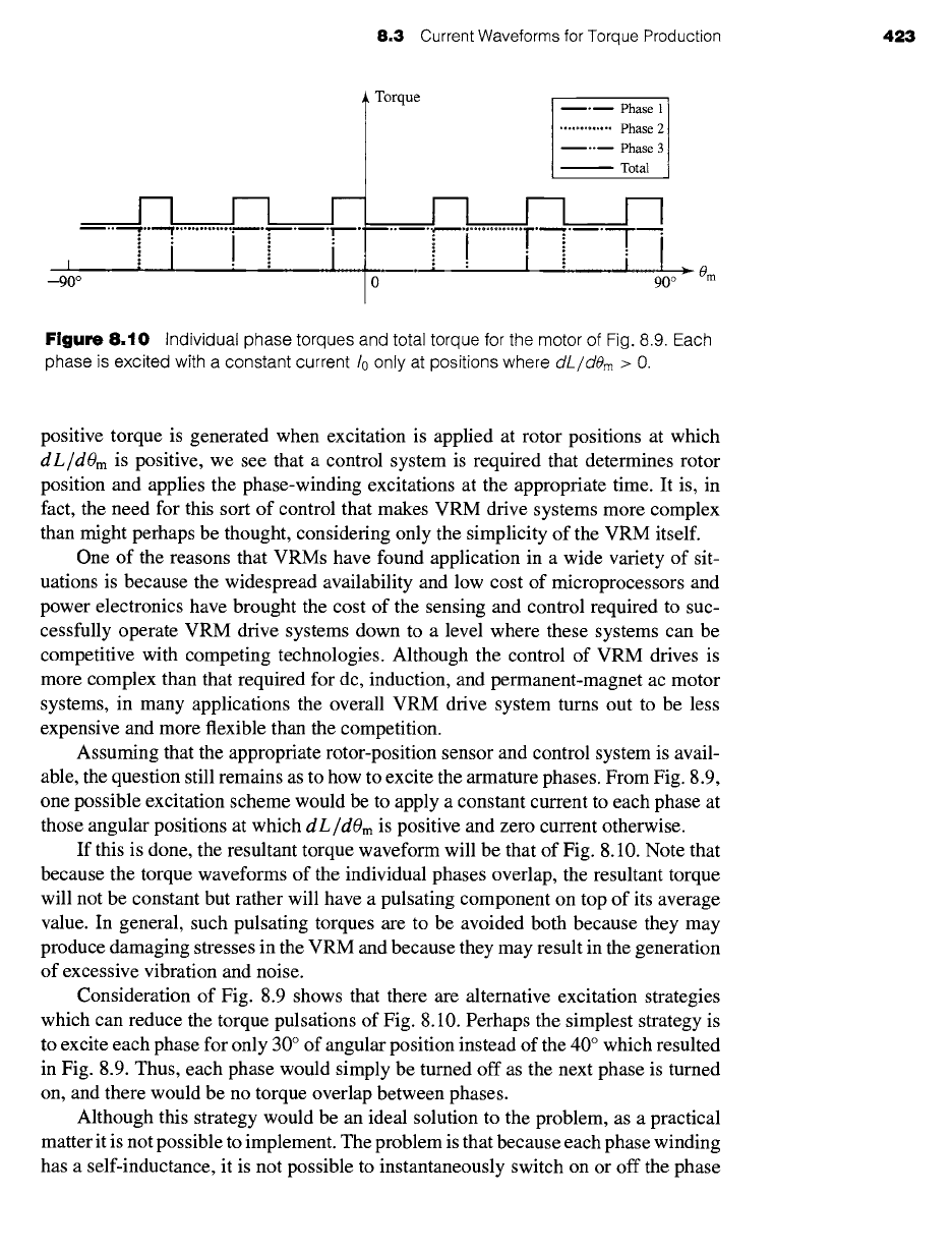
422 CHAPTER 8
Variable-Reluctance Machines and Stepping Motors
~ Phase 1
-9o o -5ooi - o
50 ° 90 °
e2
[
'-
I
, , t I I
-90 ° ! -70 t-30 ° I0 t lO °20 ° t60 ° 90 °
------I L __1 I .........
~Om
~Om
--1'0 ° 0 :30 ° 70 °;
_900 _6o0,, 'oo Io o ooi
F .. ,,.,
80 ° 90 °
• 0 m
Figure 8.9
Idealized inductance and
dL/dern
curves for a three-phase 6/4 VRM with
40 ° rotor and stator poles.
For each phase of a VRM, the phase inductance is periodic in rotor angular
position, and thus the area under the curve of
d L/dOm
calculated over a complete
period of L(0m) is zero, i.e.,
fo rt/pr dOm L(2rc/pr) -
L(0) = 0 (8.10)
d L ( Om.______~)
i
dOm
where Pr is the number of rotor poles.
The average torque produced by a VRM can be found by integrating the torque
equation (Eq. 8.9) over a complete period of rotation. Clearly, if the stator currents
are held constant, Eq. 8.10 shows that the average torque will be zero. Thus, to
produce a time-averaged torque, the stator currents must vary with rotor position. The
desired average output torque for a VRM depends on the nature of the application. For
example, motor operation requires a positive time-averaged shaft torque. Similarly,
braking or generator action requires negative time-averaged torque.
Positive torque is produced when a phase is excited at angular positions with
positive
d L/dOm
for that phase, and negative torque is produced by excitation at
positions at which
dL/dOm
is negative. Consider a three-phase, 6/4 VRM (similar to
that shown in Fig. 8.5) with 40 ° rotor and stator poles. The inductance versus rotor
position for this machine will be similar to the idealized representation shown in
Fig. 8.9.
Operation of this machine as a motor requires a net positive torque. Alternatively,
it can be operated as a generator under conditions of net negative torque. Noting that
8.3 Current Waveforms for Torque Production 423
I .....
--90 °
I I I I
i I
." .. :
Torque
Phase 1
............. Phase 2
Phase 3
Total
__1--1_____i--I_____1--I
0
90 °
Figure
8.10 Individual phase torques and total torque for the motor of Fig. 8.9. Each
phase is excited with a constant current/o only at positions where
dL/dOm > O.
positive torque is generated when excitation is applied at rotor positions at which
d L/dOm
is positive, we see that a control system is required that determines rotor
position and applies the phase-winding excitations at the appropriate time. It is, in
fact, the need for this sort of control that makes VRM drive systems more complex
than might perhaps be thought, considering only the simplicity of the VRM itself.
One of the reasons that VRMs have found application in a wide variety of sit-
uations is because the widespread availability and low cost of microprocessors and
power electronics have brought the cost of the sensing and control required to suc-
cessfully operate VRM drive systems down to a level where these systems can be
competitive with competing technologies. Although the control of VRM drives is
more complex than that required for dc, induction, and permanent-magnet ac motor
systems, in many applications the overall VRM drive system turns out to be less
expensive and more flexible than the competition.
Assuming that the appropriate rotor-position sensor and control system is avail-
able, the question still remains as to how to excite the armature phases. From Fig. 8.9,
one possible excitation scheme would be to apply a constant current to each phase at
those angular positions at which
dL/dOm
is positive and zero current otherwise.
If this is done, the resultant torque waveform will be that of Fig. 8.10. Note that
because the torque waveforms of the individual phases overlap, the resultant torque
will not be constant but rather will have a pulsating component on top of its average
value. In general, such pulsating torques are to be avoided both because they may
produce damaging stresses in the VRM and because they may result in the generation
of excessive vibration and noise.
Consideration of Fig. 8.9 shows that there are alternative excitation strategies
which can reduce the torque pulsations of Fig. 8.10. Perhaps the simplest strategy is
to excite each phase for only 30 ° of angular position instead of the 40 ° which resulted
in Fig. 8.9. Thus, each phase would simply be turned off as the next phase is turned
on, and there would be no torque overlap between phases.
Although this strategy would be an ideal solution to the problem, as a practical
matter it is not possible to implement. The problem is that because each phase winding
has a self-inductance, it is not possible to instantaneously switch on or off the phase
424 CHAPTER 8
Variable-Reluctance Machines and Stepping Motors
EXAMPLE 8.3
currents. Specifically, for a VRM with independent (uncoupled) phases, 2 the voltage-
current relationship of the jth phase is given by
d)~j
vj = Rjij + dt
(8.11)
where
Thus,
~.j = Ljj(Om)ij
(8.12)
d
vj = Rjij + --d~[Ljj(Om)ij]
(8.13)
Equation 8.13 can be rewritten as
vj = Rj + -~[Ljj(Om)] ij + Ljj(Om)~
or
dij
(8.14)
dt
dLjj(Om) dOm ] dij
vj = Rj +
d(0m)
dt ij + Ljj(Om) d----t
(8.15)
Although Eqs. 8.13 through 8.15 are mathematically complex and often require
numerical solution, they clearly indicate that some time is required to build up cur-
rents in the phase windings following application of voltage to that phase. A similar
analysis can be done for conditions associated with removal of the phase currents. The
delay time associated with current build up can limit the maximum achievable torque
while the current decay time can result in negative torque if current is still flowing
when dL(0m)/dOm reverses sign. These effects are illustrated in Example 8.3 which
also shows that in cases where winding resistance can be neglected, an approximate
solution to these equations can be found.
Consider the idealized 4/2 VRM of Example 8.1. Assume that it has a winding resistance of
R -- 1.5 ~2/phase and a leakage inductance Lt = 5 mH in each phase. For a constant rotor
speed of 4000 r/min, calculate (a) the phase-1 current as a function of time during the interval
-60 ° < 0m < 0 °, assuming that a constant voltage of V0 -- 100 V is applied to phase 1 just as
d L
1~ (0m)/d0m becomes positive (i.e., at 0m = --60 ° = --rr/3 rad), and (b) the decay of phase-1
current if a negative voltage of -200 V is applied at 0m = 0 ° and maintained until the current
reaches zero. (c) Using MATLAB t, plot these currents as well as the corresponding torque.
Also calculate the integral under the torque-versus-time plot and compare it to the integral
under the torque-versus-time curve for the time period during which the torque is positive.
2 The reader is reminded that in some cases the assumption of independent phases is not justified, and then
a more complex analysis of the VRM is required (see the discussion following the derivation of Eq. 8.5).
t MATLAB is a registered trademark of The MathWorks, Inc.
8,3
Current Waveforms for Torque Production
425
II
Solution
a. From Eq. 8.15, the differential equation governing the current buildup in phase 1 is given
by
dL11
(0m)
dOm ] dil
Pl =
R + dOm d--i- il +
L11(0m)
d-T
At 4000 r/min,
dOm Jr
O)m
d t
= 4000 r/min x 30
rad/sec
r/min
400zr
3
rad/sec
From Fig. 8.4 (for -60 ° < 0m < 0 °)
gmax( ~)
L11(Om ) ---
tl .qt_ _.~ Om .qt_ _~
= 0.005 + 0.122(0m + ~/3)
Thus
and
dL11(Om)
d0m
= 0.122 H/rad
dL11
(0m)
dOm
dOm dt
-- 51.1
which is much greater than the resistance R = 1.5 f2
This will enable us to obtain an approximate solution for the current by neglecting
the
Ri
term in Eq. 8.13. We must then solve
d(Lllil)
1) 1
dt
for which the solution is
Substituting
Vldt
Vot
il(t) = ~,u
_
Lll(t)
L11(t)
7t"
Om -- --~- +OOmt
into the expression for
Lll
(0m)
then gives
100t
il(t) = A
0.005 + 51.1t
which is valid until 0m = 0 ° at t = 2.5 msec, at which point
il
(t) = 1.88 A.
b. During the period of current decay the solution proceeds as in part (a). From Fig. 8.4,
for0 ° _< 0m _< 60 °,
dLll(Om)/dt
= -51.1 f2 and the
Ri
term can again be ignored in
Eq. 8.13.
Thus, since the applied voltage is -200 V for this time period (t >_ 2.5 msec until
il (t) = 0) in an effort to bring the current rapidly to zero, since the current must be