Gasch R., Twele J. (Eds.) Wind Power Plants: Fundamentals, Design, Construction and Operation
Подождите немного. Документ загружается.

3.2 Drive train
82
Torque support
Spur gear, 1st stage
Planet
Fast shaft
Fixed
hollow wheel
Hollow shaft (connection to
rotor shaft)
Sun wheel
Spur gear, 2nd stage
Torque support
Spur gear, 1st stage
Planet
Fast shaft
Fixed
hollow wheel
Hollow shaft (connection to
rotor shaft)
Sun wheel
Spur gear, 2nd stage
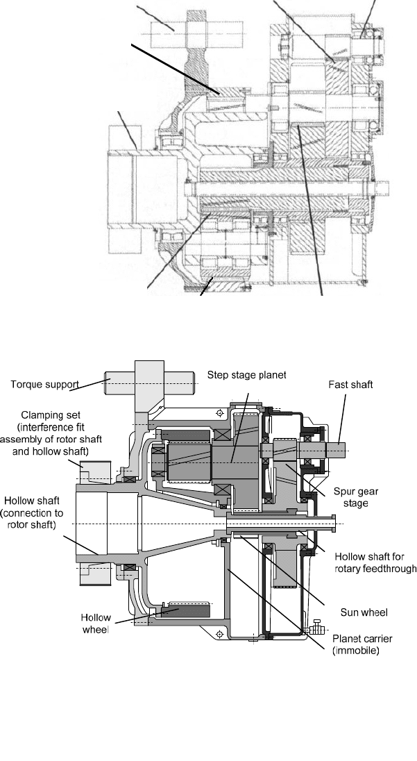
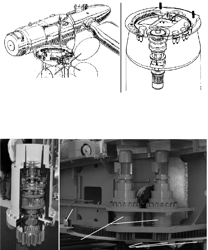
Fig. 3-39 Three-stage gearbox for wind turbines with fixed hollow wheel (Metso)
Fig. 3-40 Two-stage gearbox for wind turbines: one step stage epicyclic gear stage with rotating
hollow wheel and one spur gear stage (Renk)
3 Wind turbines - design and components
83
The advantage of the planetary gear is that the tangential force per teeth contact is
reduced by the number of planets. With three planet wheels it is F/3 under 120° at
the sun wheel and under 180° (sun and hollow wheel contact) at each planet
wheel, table 3.4. The design with a rotating hollow wheel is more complicated, but
less noise propagates directly into the casing than in the case of a fixed hollow
wheel [14].
The gearbox has to meet various demands: it should certainly operate without
any problems, have small weight and dimensions, have a low noise emission level
(above all without tonality), survive even greater damages and also be mainte-
nance-friendly [e.g. 15]. Moreover, the required lubrication has to be assured
under very different operating states, also at very low speeds (idling, start-up) [10]
and under difficult climatic conditions. These demands partially conflict in course
of the design procedure and require a very high effort when calculating statics,
dynamics, material strength and service life [15…17]. This is even increased by
the insights gained in the course of operating experience and can only be per-
formed by extensive PC based numerical calculations.
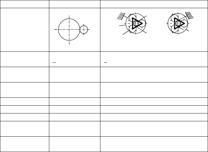
Table 3.4 Comparison of spur gears and planetary gears
Type Spur gear Planetary gear
Scheme
n
1
n
2
n
1
n
2
Planet
wheel
Rotating
planet
carrier
Sun
wheel
Hollow
wheel
Rotating
hollow
wheel
Planet
wheel
Rotating
planet
carrier
Sun
wheel
Hollow
wheel
Rotating
hollow
wheel
Hollow wheel fixed Planet carrier fixed
Transmission
ratio
<
1:5 < 1:7
Force per teeth
contact
F F/3 (with 3 planets)
Teeth contact
frequency
1 n 3 n
Weight high low
Dimensions big small
Noise emission high low
Efficiency
approx. 98% per
stage
approx. 99% per stage
Costs
Favourable for P <
500 kW
Minimum 1 planetary stage
favourable for P > 500 kW
3.2 Drive train
84
A
B
O
O
A
B
B1
A1
r
HW
r
Pc
r
Sun
Planet
Hollow wheel
Sun
Planet carrier
n
Pc
A
B
O
O
A
B
B1
A1
r
HW
r
Pc
r
Sun
Planet
Hollow wheel
Sun
Planet carrier
n
Pc
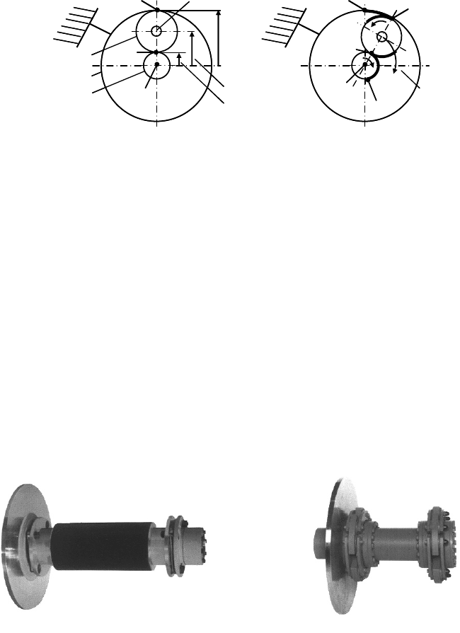
Fig. 3-41 Relations in a planetary gear with fixed hollow wheel and rotating planet carrier
3.2.3 Couplings and brakes
Due to the enormous torque, there is a rigid coupling between rotor shaft and slow
gearbox shaft. In drive trains with a three-point support of the rotor shaft, the latter
is fixed in the hollow shaft of the gearbox by an interference fit assembly (Fig.
3-40), either by shrinkage or force fitting which is easier to dismantle.
Between the fast shaft of the gearbox and the generator, only a slender shaft is
required to transmit the smaller toque. But these two shafts require an elastic cou-
pling since there may be a misalignment between the gearbox and the generator.
Moreover, both drive train components are elastically mounted on noise and vibra-
tion absorbing damper elements. So the coupling used is torsion proof but elastic
with respect to bending (multi-disk clutch, disks or steel bolts in rubber eyes),
Figs. 3-42 and 3-43. In order to protect gearbox and generator, an overload protec-
tion is often integrated in the fast shaft coupling (slipping clutch or shear bolts).
Fig. 3-42 Coupling shaft between gearbox and generator with brake disc and two couplings, left:
in leakage current isolating version, right: flexical GKG link type coupling (Winergy)
The certification guidelines of the German Lloyd [15] require two independent
braking systems. At least one of them has to act on the aerodynamic side at the
rotor. At stall-controlled wind turbines this is done by the tip brakes, i.e. the turnable
3 Wind turbines - design and components
85
blade tips (Figs. 3-2 and 3-13), whereas pitch-controlled wind turbines rotate the
entire blade (cf. chapter 3.1). The second braking system tends to be a mechanical
disk brake. At smaller wind turbines (< 600 kW) it is either found at the fast shaft
or at the low speed shaft (Fig. 3-38) which has the advantage that the loads do not
pass the gearbox when braking the rotor. But with increasing wind turbine size the
braking torque increases strongly, as does the required disk diameter. One of the
biggest commercial wind turbines with the mechanical disk brake on the low-
speed side of the gearbox is the TW-600 manufactured by Tacke (today GE
Wind).
Commercial wind turbines of more than 500 kW tend to have the disk brake on
the fast shaft, Fig. 3-43 and Figs. 3-31 to 3-35. The brake is dimensioned for ex-
treme load cases with emergency stops where the rotor has to be brought from full
load operation or over speeding to standstill within seconds. During normal opera-
tion (no emergency stop) the braking procedure activates the aerodynamic brake at
first and then the mechanical brake at small remaining torque, in order to stop the
rotor completely.
In principle, wind turbines with individual blade pitch systems do not need a
mechanical brake because the aerodynamic braking system is redundant due to
autonomous pitch drives. Basically, pitching only one blade to feather is enough to
brake the rotor from full load to standstill.
However, a mechanical brake and a rotor lock with fastening bolts are required
for maintenance and repair at the rotor and in the nacelle. In all wind turbines,
whenever staff are working at the rotor or in the hub, the rotor lock must be used
for safety purposes.
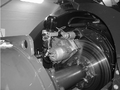
Fig. 3-43 Disc brake at the fast shaft of a gearbox (Svenborg)
3.3 Auxiliary aggregates and other components
86
3.2.4 Generators
A detailed discussion of the generators and their electrical characteristics is found
in chapter 11. So this section treats only aspects of the generator types relevant for
the drive train design. The pole number, together with the grid frequency, deter-
mines the generator speed and whether a gearbox is required or not. Asynchronous
generators which are coupled directly to the grid, employed in stall-controlled
wind turbines usually have 4, 6 or 8 poles. From a grid frequency of 50 Hz then
follows a super synchronous generator speed slightly above 1500, 1000 or 750
rpm (depending on the slip). Suitable gearbox types and their transmission ratio
were discussed in chapter 3.2.2.
Doubly-fed asynchronous generators have a variable speed but the operating
speed range is in a similar order. Only low-speed multi-pole ring generators
(separately excited or permanently magnetic excited synchronous generators) may
operate without a gearbox, Fig. 3-30.
A hybrid type is the medium-speed generator of the Multibrid M5000 with a
moderate pole number driven by a planetary gearbox, with a generator speed of
approx. 150 rpm, cf. Fig. 3-37.
With generator power of more than 1 MW, air cooling reaches its limits. So,
water cooled generators are also applied. The ring generators of gearless wind
turbines, Fig. 3-30, are large enough for effective air cooling, but the noise genera-
tion in the small gap between rotor and stator of the generator has to be
minimized.
3.3 Auxiliary aggregates and other components
3.3.1 Yaw system
In the case of historical windmills, major effort was required for the orientation of
the rotor perpendicular to the wind. The miller had the troublesome task of
pushing the tailpole in order to adjust the rotor to the variable wind direction, see
chapter 2. Only in the middle of the 18
th
century, did the invention of the fantail
allow the yawing process to be automated. Even today the yaw system is a “non-
trivial” functional subsystem of the wind turbine.
Wind turbines with a horizontal rotor axis orientation allow either
x passive yaw systems - e.g. autonomous yawing of a turbine with a
downwind rotor or windvanes at upwind rotor turbines - or
3 Wind turbines - design and components
87
x active yaw systems are applied - e.g. a fantail or yaw drives driven by
external energy (also known as azimuth drives).
As already explained in section 3.1, the downwind rotor (leeward in relation to
the tower, e.g. SÜDWIND; Fig. 3-18) is suitable for autonomous passive yawing
of the wind turbine because if the wind direction is not parallel to the rotor axis,
the force from the wind pressure on the rotor causes a yaw moment around the
tower axis which adjusts the rotor to the wind direction, similar to a windvane. But
for wind turbines with a high tip speed ratio, which have a relatively low solidity
of the rotor area, this works only when the rotor is turning. Hence, for low wind
speeds either the nacelle housing itself has a passive function as a kind of addi-
tional “windvane”, or an active drive is required.
The windvane for passive yawing of upwind rotor turbines is a characteristic of
the Western mill, cf. Figs. 2-10, 3-1 and chapter 12. Due to its simple system de-
sign and the fact that neither external energy nor control is required, it is also
commonly used in other small wind turbines, especially battery chargers.
Passive yaw systems have to be designed in such a way that sudden changes in the
wind direction do not provoke fast yaw movements producing strong additional
loads due to gyroscopic forces. At single- and two-bladed rotors the situation is
even worse. The inertia against yawing depends on the angular rotor blade posi-
tion which increases the strong dynamic loads. Therefore, the application of pas-
sive yaw systems is limited in general to a rotor diameter of up to 10 m.
Active yaw systems position the nacelle using drive units and are applied in
wind turbines of both upwind and downwind rotor configuration. No external
energy is needed if the wind itself is driving the fantail, orientated perpendicular
to the rotor as in the Dutch smock windmills, Figs. 2-8 and 2-12. The torque from
this small auxiliary rotor (rosette), Fig. 3-44, is transmitted using a worm gear
with a high transmission ratio (up to 4,000) to the rotating assembly of the yaw
system.
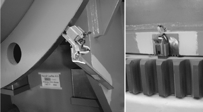
A yaw system with one or more electrical or hydraulic yaw drives is most
common for larger wind turbines. They are controlled using the signal from a
small windvane on top of the nacelle, Figs. 3-30 and 3-32, and act on the spur gear
of the big rotating assembly at the tower-nacelle connection, Figs. 3-44 right and
3-45 right. Multi-MW wind turbines may have up to eight yaw drives.
Since there is always an unavoidable clearance in this spur gear system, nacelle
oscillations, which would increase wear of the teeth flanks, have to be prevented.
For this purpose, the nacelle is either fixed by yaw brakes which are released only
during a yawing movement, and/or additional friction brakes are permanently act-
ing. The yaw drive then has to work against this friction force. If several electrical
yaw drives are installed, another possibility is locking the yaw system “on the
electrical side”: when the yaw movement is completed, half of the drives get the
signal to “try to turn” into the other direction. The drives work against each other,
and the fixing torque assures in each yaw gear teeth contact on a defined flank.
When designing the wind turbine, the fact that the active yaw system couples
3.3 Auxiliary aggregates and other components
88
nacelle and tower rigidly has to be taken into account. Torsional oscillations of the
tower are transferred into the nacelle.
Fig. 3-44 Left: wind turbine with rosette for yawing (Allgaier) [19]; right: yaw bearing with yaw
drive and yaw brakes (Wind World)
Yaw drives Yaw brakes
Nacelle frame
Yaw angle
sensor
Yaw drives Yaw brakes
Nacelle frame
Yaw angle
sensor
Yaw drives Yaw brakes
Nacelle frame
Yaw angle
sensor
Fig. 3-45 Left: section of a yaw drive with multi-stage planetary gear, motor removed
(Liebherr); right: electrical yaw drive, yaw brakes and yaw angle sensor (REpower)
3 Wind turbines - design and components
89
3.3.2 Heating and cooling
Wind turbines have to operate within a large temperature range based on the cli-
matic conditions on site. Moreover, the heat losses of gearbox and generator heat
up the nacelle. The temperatures should not exceed the admissible operating range
of the installed components, above all the sensible electronics. For a defined heat
removal, the air flow is directed by special ventilation systems. Their design has to
consider also the minimisation of noise emission and airborne sound propagation.
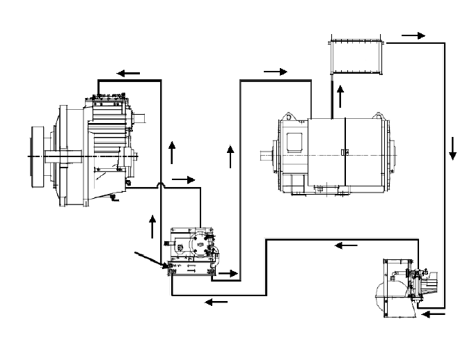
Apart from the cooling system for the nacelle itself, there are separate coolers
e.g. for the drive train components gearbox and generator, Figs. 3-34 and 3-36.
Since the admissible temperature level of the generator is often higher than that of
the gearbox, a combined oil-water-cooling cycle may be used, Fig. 3-46. The
water-air cooler is often located outside the nacelle, which may then be encapsulated
completely, e.g. for air conditioning in offshore applications. If the gearbox oil is
overheated, the lubrication properties may degrade due to the destruction of the
additives, and the service life of the gearbox may be reduced significantly.
In the winter time, the ambient temperatures may fall below 0°C, even outside
of cold climate sites. After a longer standstill, the gearbox oil also becomes cold
and its viscosity increases, causing lubrication problems during the wind turbines’
start-up. To assure good lubrication, additional heaters are then installed. More-
over, the temperatures in the electronic cabinets should not go below the allowed
range. An encapsulation of the nacelle or entire wind turbine e.g. with shutters at
all ventilation openings is suitable, but the effective cooling of the nacelle should
not be disturbed in summertime.
Moreover, rotor blade heating systems are installed, if there is increased risk of
icing. Ice on the blades changes the aerodynamic characteristics drastically and
causes increased vibrations due to the additional mass unbalance of the rotor.
Negative influences of condensation water in the blade are also reduced by the
rotor blade heating, which is either done electrically with heating wires in the
blade laminate or by blowing hot air from the nacelle into the hub and blades.
Heated anemometers and wind vanes are also useful under icing conditions. A
frozen anemometer would cause e.g. yield loss because the wind turbine cannot
start despite good wind speed. A frozen windvane may suggest, depending on the
relative angle to the rotor axis, a permanently occurring deviation of the wind
direction causing permanent yawing - or it may hide existing wind direction devia-
tions causing yaw angle errors with additional loads. Both pose a potential
dangerous to the wind turbine, see e.g. [20].
3.3 Auxiliary aggregates and other components
90
Gear oil
Cooling water
Cooling water
Plate heat exchanger
Oil - water
Gearbox
Generator
Water - air - Cooler
Pump station
Gear oil
Cooling water
Cooling water
Plate heat exchanger
Oil - water
Gearbox
Generator
Water - air - Cooler
Pump station
Fig. 3-46 Combined Oil - water - cooling cycle for gearbox and generator (Nordex)
3.3.3 Lightning protection
Lightning is a potential danger to wind turbines because of their large total height
and their installation at exposed sites. Accordingly, there are guidelines for the de-
sign of the lightning system, e.g. IEC 61400-24, see table 9.1. Statistically, a wind
turbine in Germany is only struck once every 10 years by lightning [21, 22], but at
exposed sites in the German highlands this number is significantly higher. Often,
the flash strikes the turbine at the highest point, i.e. the blade tip. However, in the
case of large wind turbines of the MW class, a flash may be propagate upwards
from the turbine into the clouds.
Rotor blades are often equipped with special lightning receptors in the blade tip
area. These are metal disks of approx. 5 cm diameter integrated into the blade sur-
face. Other manufacturers install several receptors along the blade radius. Or the
blade tip as well as the leading and trailing edge are made from aluminium. The
high lightning currents (up to 1000 kA) are conducted in a defined way e.g. by
metal cables inside the rotor blade. If condensation water in the rotor blade were
to heat up and evaporate by lightning energy, the blade would explode. Many
blade manufacturers install lightning registration cards at each blade root to record
3 Wind turbines - design and components
91
the currents. Later analysis provides the basis for detecting potential blade
damage.
In order to protect the entire wind turbine against lightning damage the currents
have to be conducted further down into the ground. It is important to protect the
bearings as the high currents would point-weld together the balls and the running
surface.
Fig. 3-47 Components of the lightning protection system for the protection of the bearings; left:
sliding brush contact on the main shaft, right: on the yaw drive, combined with spark gaps (RE-
power)
To prevent this, spark gaps and/or sliding contacts with carbon brushes are in-
stalled, Fig. 3-47. The first crucial point in a wind turbine with a pitch system is
the blade bearing between rotor blade and hub, the second is the rotor bearing be-
tween hub and nacelle frame, and the third is the yaw bearing between nacelle
frame and tower. The scheme of the lightning protection system with the different
lightning protection zones (LPZ) is shown in Fig. 3-48. LPZ 0, e.g., means that the
object (rotor, nacelle top with wind sensors) may be directly hit by the strike.
From inside the tower down to the earth rod, the required protection measures are
the same as for technical buildings. Electronic components, the control, switch-
gear, transformers, etc. have additional surge and lightning protection.
Only approx. 30% of the lightning damages at wind turbines in Germany result
from direct strikes, while approx. 60% are caused by strikes into the power and
telecommunication lines. Therefore, an entire lightning protection concept accord-
ing to the standards is required [21]. A periodic inspection of the grounding resis-
tance is required to assure that the lightning protection system functions properly
under operation from the rotor blade down to the ground.