Gasch R., Twele J. (Eds.) Wind Power Plants: Fundamentals, Design, Construction and Operation
Подождите немного. Документ загружается.

3.1 Rotor
52
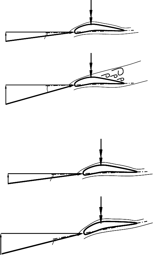
the flow remains attached to the profile, however larger pitch angles are required..
Fig. 3-7 shows the comparison of typical power curves for these two concepts of
power limitation. Both methods of pitching the blade – to stall or to feather - are
extensively discussed in chapters 6 and 12.
v
v = 8 m/s
:
D
A
u = const
w
v
v = 16 m/s
:
D
A
u = const
w
v
v = 8 m/s
:
D
A
u = const
w
v
v = 8 m/s
:
D
A
u = const
w
v
v = 16 m/s
:
D
A
u = const
w
v
v = 16 m/s
:
D
A
u = const
w
Fig. 3-5 Schematic view of the stall effect (limiting power at wind speed higher than rated wind
speed)
v
v = 8 m/s
:
D
A
u
w
v
v = 16 m/s
:
u = const
w
D
A
v
v = 8 m/s
:
D
A
u
w
v
v = 8 m/s
:
D
A
u
w
v
v = 16 m/s
:
u = const
w
D
A
v
v = 16 m/s
:
u = const
w
D
A
Fig. 3-6 Schematic view of “Pitching to feather” (limiting power at wind speed higher than rated
wind speed)
3 Wind turbines - design and components
53
0
100
200
300
400
500
600
700
0 2 4 6 8 10 12 14 16 18 20
Windgeschwindigkeit v in m/s
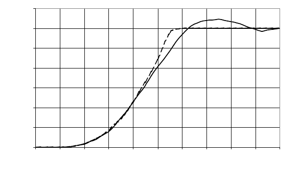
Leistung P in kW .
stall
pitch
Wind speed v [m/s]
Power P [kW]
0
100
200
300
400
500
600
700
0 2 4 6 8 10 12 14 16 18 20
Windgeschwindigkeit v in m/s
Leistung P in kW .
stall
pitch
Wind speed v [m/s]
Power P [kW]
Fig. 3-7 Comparison of stall and pitch control: Power curves of two 600 kW wind turbines, data
from type approval test reports; e.g. in [24]
3.1.1 Rotor blade
The design of the single rotor blade is determined by the selected aerodynamic
profiles, the inner and outer geometry and as well as the chosen materials.
As it will be discussed in detail in chapter 5, the required quality of the aero-
dynamic profile depends on the chosen design tip speed ratio. Western mills (Fig.
3-3, left) only require the profile of a cambered plate, whereas wind turbines for
electricity generation require high-quality profiles with a high ratio of lift and drag
coefficient (i.e. high lift/drag ratio).
The aerodynamic profiles of the NACA44XX and NACA63XXX series are
very common, but today there are also aerodynamic profiles developed specifi-
cally for wind turbine rotors, see Fig. 3-8.
Above all, a high lift/drag ratio is important in the area of the blade tip. The
circumferential speed in the inner blade part is smaller, which leads to a smaller
local relative velocity and local speed ratio. Therefore, the profile chord length has
to be larger which allows thicker profiles to be applied in this rotor section, (cf.
chapter 5). This is helpful for the reduction of the large material’s stress, as the
highest loads are found at the blade root. Hence, different aerodynamic profiles
are used in the inner and outer part of the rotor blade. Fig. 3-8 shows a typical dis-
tribution of different profile geometries along the blade radius.

3.1 Rotor
54
Fig. 3-8 Different blade profiles along the radius of a blade, (EUROS)
Center of elasticity
30% c
Center of gravity
Radial line (often pitch axis)
Aerodynamic
pressure line
Airfoil cord length c
Suction side
Pressure side
BondingBonding
Belt Web
Center of elasticity
30% c 30% c
Center of gravity
Radial line (often pitch axis)
Aerodynamic
pressure line
Airfoil cord length c
Suction side
Pressure side
BondingBonding
Belt Web
Fig. 3-9 Blade section - characteristic lines of the blade dynamics
In the design calculations of rotor blades (statics, vibrations, flutter etc.) the posi-
tion of four lines, which pass radially along the blade, Fig. 3-9, is of great impor-
tance:
x The radial line is the axis of rotation of the blade pitch mechanism, resp.
the line in the blade flange centre perpendicular to the rotor shaft axis
x The elastic line (centre of elasticity) is the position of the shear centre
line in the supporting structure (approx. centre of gravity of the main
3 Wind turbines - design and components
55
spar). The elastic deformations of the flap- and edge-wise movements are
counted from here as well as the twist of the blade section caused by tor-
sional moments
x The line of the centres of gravity represents the points of action of forces
resulting from inertia and weight
x The pressure line consists of the points of attack of the lift and drag
forces. When the flow is attached, it is approx. 30% of the chord length.
If e.g. the stall effect occurs when exceeding the rated wind speed the
pressure line will move which may cause the rotor blade to vibrate (stall
flutter). These vibrations can be reduced by vibration dampers (contain-
ing liquids) in the blade tip. In order to provoke the stall effect along a
defined line on the blade surface and prevent it from oscillating, some
stall-regulated wind turbines are equipped with vortex generators (stall
stripes) on their blade surface.
The necessary quality of the aerodynamic profile generates requirements in rela-
tion to the production process and the applied materials of the rotor blade. The
simple profile of a Western mill, Fig. 3-3 left, is manufactured from cambered
steel plates.
The rotor blades for electricity generating wind turbines, designed with a high
tip speed ratio, Fig. 3-3 middle and right, have to meet higher demands. Their pro-
files are mostly laminated with glass fibre reinforced plastics (GFRP), and, most
recently, with carbon fibre reinforced plastics (CFRP). The latter are more expen-
sive, but their admissible material strength is up to three times higher than that of
GFRP, Fig. 3-10. Their fatigue strength also tends to be higher which is ideal for
lightweight design.
The separate moulds for the suction and pressure side of the blade (Fig. 3-11)
are covered with the woven fibre fabrics (rovings), which are then soaked with
polyester or epoxy resin. Today, this is mostly done automatically in a vacuum
process in order to reduce the adverse health effects for the workers, prevent air
bubbles which reduce the material strength and achieve a more defined material
usage. After evacuating the mould sealed with a plastic film, the resin is pumped
into the mould at defined points. Some rovings types are delivered already soaked
with resin (so-called “pre-pregs”). Moreover, some manufacturers use so-called
sandwich-constructions where balsa wood is located in between the inner and
outer rovings. In a defined heating cycle the resin is hardened, and finally the two
halves of the blade are bonded together. The spar of the GFRP blade, which pro-
vides defined geometry and material strength, is filled with foam and/or addition-
ally stiffened by GFRP ribs, webs and belts (Fig. 3-9). The final coating has to be
weather-proof and UV resistant.
Erosion protection film is attached to the leading edge to reduce the abrasive
material removal under operation. Flow controlling elements are applied on the
blades, e.g. vortex generators, to assure defined flow conditions and flow direction
despite the wind fluctuating by time and once per revolution due to the wind
profile.
3.1 Rotor
56
Stiffness in GPa
Tensile strength in MPa
Glass fibre
Carbon fibre
Stiffness in GPa
Tensile strength in MPa
Glass fibreGlass fibre
Carbon fibreCarbon fibre
Fig. 3-10 Material strength values of glass and carbon fibres, (EUROS)
Fig. 3-11 Blade production, separate moulds for suction side and pressure side, mould in front:
soaking of the laminate with epoxy resin by a vacuum process (NOI)
3 Wind turbines - design and components
57
Fig. 3-12 Connection of rotor blade at hub: left “IKEA-bolts” (Bonus), right: bolt sleeves
(Vestas)
Blade tip
activated by
centrifugal force
Pre-stressing
spring
Return cylinder
Hydraulic
pipe
Blade tip
activated by
centrifugal force
Pre-stressing
spring
Return cylinder
Hydraulic
pipe
Fig. 3-13 Rotor blade with tip brake (turning the blade tip) (LM, [6])

3.1 Rotor
58
The load transmission from the GFRP rotor blade to the metal flange of the hub is
a tricky issue (Fig. 3-12). For this screw connection with the hub, there are used
either sleeves for stud bolts laminated into the blade root, or the so-called “Ikea-
connection” with a cross bolt
Another design detail which needs special attention is the turnable blade tip of
stall-regulated rotors which serves as an aerodynamic brake. Activated by cen-
trifugal forces, it deploys when the rotor is over-speeding (Fig. 3-2 and 3-13). For
braking, a threaded guidance turns the blade tip by 90°, so it is nearly perpendicu-
lar to the relative velocity. Since the turnable blade tip is located at the maximum
radius, the affected ring section, and as well the resulting braking force and torque,
are very large.
The specific blade properties change with increasing size. Light weight design
is an imperative, above all for the rotor blades of the Megawatt turbines. If the
rotor blades were scaled up using the laws of similarity (cf. chapter 7), the weight
of the rotor blades would increase with the cube of the blade radius (m ~ r³). The
large weight would cause enormous bending forces and correspondingly high
stress causing problems with the material strength. Fig. 3-14 shows the blade mass
of commercial rotor blades versus the rotor diameter. The interpolation curves
have an exponent of approx. 2.2 instead of 3.0, thanks to the lightweight design.
Moreover, the diagram illustrates that when it comes to the rotor blade weight, it is
advantageous to use epoxy instead of polyester resin.
Rotor blade weight/ (kg)
Fig. 3-14 Rotor blade weight depending on rotor diameter and material, (EUROS)
3 Wind turbines - design and components
59
3.1.2 Hub
There are various possibilities for the design of the hub and the attachment of the
blades. Most of them were tested in the 1980s at prototype turbines of different
sizes. In the following, these variants are presented. Although the rigid hub is used
nearly exclusively for commercial wind turbines (Figs. 3-15 and 3-23). Perhaps
the other hub types will be considered again during future developments because
they help to reduce stress and thus component weight.
The rotor blade connection to the hub can be made
- rigid or
- flexible by using a hinge (flapping), see Fig. 3-16. Another special hub type
can be used at two-bladed rotors where the two blades are fixed together rigidly
and have a common hinge in the hub, called the teetering hinge. All of these three
types of blade-hub connection may be combined with a controlled pitching of the
blade around its axis for power and rotor speed limitation. Theoretically, move-
ment can also occur around the third axis at the blade-hub connection, the slewing
axis. However, this is not used in practice. Instead, in order to compensate alter-
nating loads (torque peaks) in this direction, additional components are included in
the drive train (special couplings or the elastic support of the gearbox). Fig. 3-17
gives an overview of different hub types and the stress relief achieved in the blade
root and rotor shaft.
Fig. 3-15 Nacelle with rigid hub of a three-bladed rotor (photo by company Zollern)

3.1 Rotor
60
:
Fig. 3-16 Denomination of the axes at the blade flange
The flapping hinge rotor is a characteristic of the SÜDWIND 1237 which has a
downwind rotor (Fig. 3-18). The flapping hinge at each rotor blade relieves the
blade root and the rotor shaft from all bending stress around the flapping axis.
Such bending stress results from the ‘wind pressure’ (i.e. thrust) and the three-
dimensional non-uniform wind velocity field (Fig. 3-19). At a hub with rigid blade
connection the stochastic spatial fluctuations of the wind in the rotor swept area
cause an eccentricity of the point of action of the resultant forces from the rotor
axis leading to bending stress in the rotor shaft. This is also avoided by flapping
hinges.
During operation, a balance is created between the centrifugal forces F
C
and the
thrust F
T
at the rotor, Fig. 3-21. This causes a self-adjusting of the flapping angle
and also its limitation, typically below 10°. Larger cone angles only occur if the
centrifugal forces are too small due to low rotor speed, i.e. shortly before rotor
standstill. Additional components in the rotor are therefore required - e.g. return
springs (SÜDWIND), stoppers, gear or hydraulic components - to assure the start
up of the wind turbine. These components are complicated and costly, hence the
flapping hinge principle is seldom applied to larger rotors [7].

3 Wind turbines - design and components
61
v
O
v
Blattanschluss ... starr starr und pitchend schlagend
Blade-hub
connection …
rigid
rigid with
pitch
flapping teetering
Reduces all flapwise
bending moments in the
blade root and also the
alternating bending
moments in the rotor shaft
due to the spatially
inhomogeneous wind field
High, alternating
bending loads in the
rotor shaft and
alternating flapwise
bending loads at the
blade root
Reduces in all turbine
components at strong
wind and storm the
loads due to the mean
aerodynamic forces
Reduces the alternating
bending moments in the
rotor shaft due to the
spatially inhomogeneous
wind field and reduces also
the dynamic components of
the flapwise bending
moment in the blade root
:
v
v
v
O
v
Blattanschluss ... starr starr und pitchend schlagend
Blade-hub
connection …
rigid
rigid with
pitch
flapping teetering
Reduces all flapwise
bending moments in the
blade root and also the
alternating bending
moments in the rotor shaft
due to the spatially
inhomogeneous wind field
High, alternating
bending loads in the
rotor shaft and
alternating flapwise
bending loads at the
blade root
Reduces in all turbine
components at strong
wind and storm the
loads due to the mean
aerodynamic forces
Reduces the alternating
bending moments in the
rotor shaft due to the
spatially inhomogeneous
wind field and reduces also
the dynamic components of
the flapwise bending
moment in the blade root
:
v
v
Fig. 3-17 Different hub design types