Gasch R., Twele J. (Eds.) Wind Power Plants: Fundamentals, Design, Construction and Operation
Подождите немного. Документ загружается.

3.1 Rotor
62
v
Return spring
v
Return spring
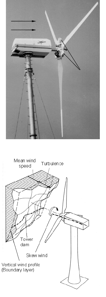
Fig. 3-18 Wind turbine SÜDWIND 1237, downwind rotor with flapping hinge
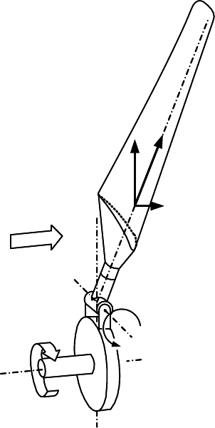
Fig. 3-19 Three-dimensional wind velocity field in front of the wind turbine, [6] modified
3 Wind turbines - design and components
63
:
F
C
F
T
F
r
v
M
B
= 0
:
F
C
F
T
F
r
v
M
B
= 0
Fig. 3-20 Equilibrium of forces at the flapping hinge rotor
The flapping hinge reduces in the blade root the bending stress around the profile
chord where the section modulus is small due to the slender profile sections. This
way, the rotor blade weight may be reduced by up to 75%. At least for the design
point, rotors with a rigid hub may also benefit from the effect of the partial com-
pensation of thrust forces and the centrifugal forces, used at flapping hinge rotors.
A fixed flapping angle may be introduced, which is then called cone angle.
A design which was developed specifically for to the two-bladed rotor is the
teetering hub (Figs. 3-17 and 3-21). It reduces loads arising from spatial fluctua-
tions of the wind. The rotor shaft is primarily relieved of the corresponding bend-
ing stress. At the rotor blade root, only the dynamic portion of the flapwise bend-
ing moment is reduced. The design principle of the teetering hub has been applied
mainly for large downwind turbines, e.g. GROWIAN (Fig. 3-21) and WTS-3. Due
to the large size of the turbine, the atmospheric boundary layer led to a signifi-
cantly different wind speed at the top and bottom position of the blade thus chang-
ing flow conditions during the rotation. Due to the downwind position of the rotor,
3.1 Rotor
64
this asymmetry is even increased. This is primarily because, at its bottom position,
the blade passes through the velocity deficit of the tower wake.
The effect of the teetering hub even improves if coupled with blade pitching.
This was successfully done at the Maglarp wind turbine (WTS-3) and in the 1940s
at the Smith-Putnam turbine (Fig. 2-15).
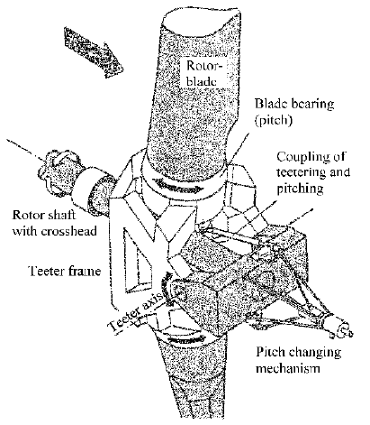
The coupling of teetering and pitch movement - which is called G
3
-coupling in
accordance with the corresponding principle in helicopter design - is also used for
hubs of one-bladed rotors. Its design is similar to that of the teetering hub. How-
ever, the physical principle is a combination of flapping hub and pitch hub. Fig.
3-22 shows that it is relatively easy to build such a complex hub by using a car-
danic suspension. However, the cardanic suspension is imperative for this design,
due to its dynamic particularities [8, 9].
Allowing an additional degree of freedom in the connection between rotor
blade and hub has mainly the effect of stress reduction in the whole drive train, on
the one hand. On the other, in the case of wind turbines in the MW range, the re-
quired construction is costly and susceptible to faults due to the heavy rotor
weight and the big loads. Therefore, the concept of the rigid hub (Figs. 3-15 and
3-23) is preferred in practice, apart from some wind turbines for research and
some other prototypes. There are two types of mounting the blades to a rigid hub:
x fixed blade angle, i.e. no blade pitching (stall concept) and
x variable blade angle by pitching the rotor blades (pitch concept).
Fig. 3-21 Teetering hub of GROWIAN [26]
3 Wind turbines - design and components
65
Flapping
Pitching
Pitch
mechanism
į
3
Flapping
Pitching
Pitch
mechanism
į
3
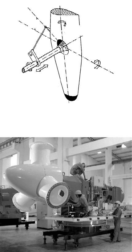
Fig. 3-22 Flapping pitch hub with cardanic suspension of FLAIR [8]
Fig. 3-23 350 kW wind turbine with rigid hub and integrated drive train (Suzlon)
The weight of the hub increases significantly with the growing size of the wind
turbine. Due to their size, casting of the hub is limited to a few foundries. The
material is nodular graphite cast iron (e.g. EN-GJS-400-18-LT, formerly known as
GGG-40.3). A spherical hub has a comparatively small hub weight, but it is dis-
advantageous as far as stress-minimising design is concerned. Some hub designs
include an extender to reach larger higher rotor diameters with the same hub and
rotor blade.
3.1 Rotor
66
For hub design optimisation FEM software is used. This results in topologically
shaped hubs and achieves weight and stress reduction, cf. Fig. 9-9 in chapter 9.4.
By pitching the blade around its blade axis (Figs. 3-16, 3-17 and 3-22), the
blade pitch angle and consequently the angle of attack and the aerodynamic forces
are changed. Pitching influences the power output, as described in Figs. 3-6 and
3-7, and is therefore suitable for power limitation.
Pitching the blade in the direction of the feather position not only reduces the
driving forces but all forces at the rotor blade and therefore also the resulting
stress. By ‘pitching to feather’ the quasi static loads from the mean aerodynamic
forces are reduced at strong wind conditions and during storm. The construction of
the blade pitch system is described in the following section.
3.1.3 Blade pitch system
A significant effort is needed to build a rotor with a pitchable blade, regardless of
whether it is to be pitched to feather (reduction of lift force) or to flow separation,
i.e. stall (‘active stall’). The blade bearing and the pitch drive have to be designed;
moreover the blade has to be positioned precisely and firmly.
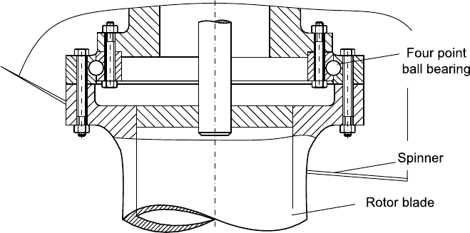
The blade bearing, Fig. 3-24, transfers the driving torque and the thrust as well
as the centrifugal force and the bending moment from the blade weight. Single or
double row four-point ball bearings are common.
The blade pitch system is driven by mechanical, hydraulic or electrical energy.
In normal operation, a synchronous pitching has to be assured, no matter which
drive concept is applied, else the aerodynamic forces become asymmetrically
causing an aerodynamic unbalance.
Fig. 3-24 Section of a blade pitch four point ball bearing (INA)
3 Wind turbines - design and components
67
:
Normalbetrieb Regeln Sturmstellung
Vorspannfeder Fliehgewicht
v
u
c
:
Normalbetrieb Regeln Sturmstellung
Vorspannfeder Fliehgewicht
:
Normalbetrieb Regeln Sturmstellung
Vorspannfeder Fliehgewicht
v
u
c
v
u
v
u
c
Normal Operation Pitch control Storm
Pre-loading spring Flyball weight
:
v
w
u
:
Normalbetrieb Regeln Sturmstellung
Vorspannfeder Fliehgewicht
v
u
c
:
Normalbetrieb Regeln Sturmstellung
Vorspannfeder Fliehgewicht
:
Normalbetrieb Regeln Sturmstellung
Vorspannfeder Fliehgewicht
v
u
c
v
u
v
u
c
Normal Operation Pitch control Storm
Pre-loading spring Flyball weight
:
v
w
u
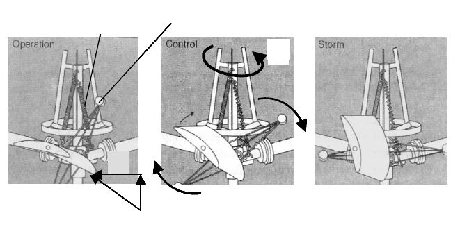
Fig. 3-25 Brümmer hub with blade pitch control by flyball weights
The synchronous pitch is achieved either with a central drive unit acting simulta-
neously on all three rotor blades (e.g. Adler 25, ENERCON E-32, DEwind D4,
Vestas V44 or Zond 750), cf. Figs. 3-26 and 3-29. Or the pitch angles of the three
blades are measured separately, and the controller adjusts the individual blade
pitch, cf. Figs. 3-27 and 3-30.
Recently, more complex control systems were developed, and are now being
applied at some Multi-MW wind turbines, which measure the loads at the blade
and consider them in the individual blade pitch control. This reduces the dynamic
loads significantly.
Moreover, the blade pitch system has to be designed as a “fail-safe system”
since it is often one of the two required safety braking systems. When a dangerous
operating state occurs (e.g. over-speeding or emergency stop), the blade pitch has
to bring the rotor blade to the feather position immediately. In the case of shortage
of the external energy, this is done by stored mechanical, electrical or hydraulic
energy.
Using mechanical energy for the blade pitch is more suitable at smaller wind
turbines (rated power less than 100 kW). Either the blade weight itself or addi-
tional fly weights are used to create the acting centrifugal forces. Fig. 3-25 shows
the design of a mechanically driven blade pitch with additional fly weights. The
fly ball weights are specially arranged in order to create the acting torque (propel-
ler moment) around the blade axis. A pre-stressed spring creates a defined counter
torque to determine the start of pitching. Since the acting centrifugal forces origin
from the rotation of the fly ball weights, the requirement of being a fail-safe sys-
tem is always fulfilled. The rotor is protected against over-speeding without any
need for an external energy supply.
3.1 Rotor
68
Pitch mechanism
Hydraulic
aggregate
Central hydraulic
pitch cylinder
Return spring
Push rod
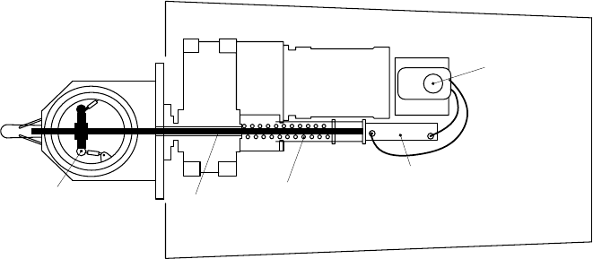
Fig. 3-26 Wind turbine Windmaster, central hydraulic pitch mechanism with push rod [6]
A hydraulic blade pitch system is applied at wind turbines with rated power from
the 300 kW to the Multi-MW range. Fig. 3-26 shows a hydraulic central pitch sys-
tem with a push rod transferring the pitch movement to the three rotor blades. Hy-
draulic drives are also used in some individual blade pitch systems (Südwind S.46,
Vestas V52 to V90/ 3 MW). The weak points are the rotary joints and the leak-
tightness in the rotating system. The required back-up energy for the fail-safe sys-
tem is stored in hydraulic pressure accumulators in the hub. Additional safety
measures have to be taken in order to prevent, in case of leakage or damage to the
hydraulic system, the area and soil around the wind turbine suffering any ecologi-
cally problematic consequences.
An electrical blade pitch system is common to most of the wind turbine types.
Nearly all manufacturers trust in this solution for the pitch, especially for larger
wind turbines (rated power above 500 kW). A central pitch system is no longer
suitable in this case due to the high acting forces and the space required. There-
fore, the pitching of the three rotor blades is performed by three individual gear
motors, Figs. 3-27 and 3-30. At wind turbines above 500 kW the rotor blade pitch-
ing speed is in the range of 5° to 10° per second. Therefore, the gear motors need a
very high transmission ratio created by multi-stage planetary gears or worm gears.
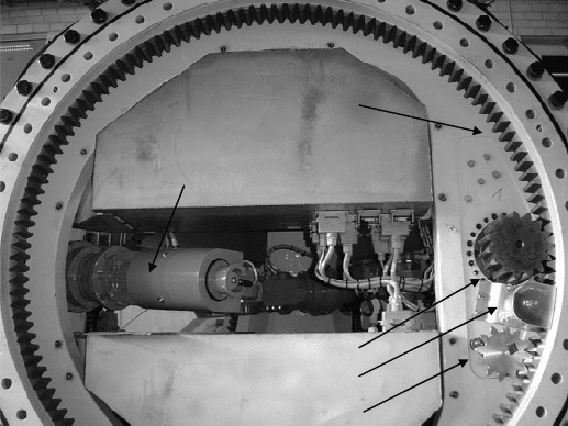
For an exact positioning of the rotor blades, angular encoders are required to
measure the actual blade position and report it to the pitch controller. The latter is
often located in the rotating hub to prevent disturbances resulting from the signal
transfer between the stationary nacelle and the rotating system of the rotor. For the
fail-safe requirement of the electrical pitch system, the accumulators have to be in-
tegrated in the rotor hub. This location has disadvantages for the maintenance and
the required periodical exchange of the accumulators due to their limited lifetime.
3 Wind turbines - design and components
69
Internal gear wheel
Rotating accumulator
and pitch control unit
Electrical pitch motor
Positioning pinion
Lubrication
Pitch angle sensor
Internal gear wheel
Rotating accumulator
and pitch control unit
Electrical pitch motor
Positioning pinion
Lubrication
Pitch angle sensor
Fig. 3-27 Hub of a pitch-controlled 1,5 MW wind turbine with electrical gear motors (REpower)
Alternatively, the application of super capacitors is on the rise. The amount of
stored energy has to serve for only one complete pitch movement to the feather
position (park position). Another advantage of three individual pitch drives is that
if one pitch drive fails the remaining two are still effective enough to protect the
wind turbine against over-speeding and bring the rotor to stop.
3.2 Drive train
3.2.1 Concepts
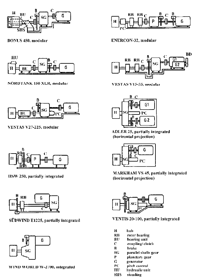
There are different ways of drive train component arrangements (Fig. 3-28). Con-
sidering the development of commercial wind turbines from the 1980s on, there is
no obvious “ultimate solution”. However, the design engineers of different manu-
facturers seem to have different design philosophies. Several manufacturers even
changed their drive train design with the growth in wind turbine size. The two
basic concepts are
x the integrated drive train where different components with their different
functions are fixed directly together and
x the modular drive train where most of the components are fixed sepa-
rately on the nacelle frame.
3.2 Drive train
70
Fig. 3-28 Drive train concepts for various turbines
A mixed type is the partially integrated drive train where the rotor shaft support
and the gearbox support are combined.
3 Wind turbines - design and components
71
At the beginning of the 1990s, most of the Danish manufacturers trusted in the
modular drive train design with a separate bearing unit for the rotor. Gearbox and
generator were also fixed separately on the nacelle frame, Figs. 3-2 and 3-29. The
advantages of this drive train type are the good accessibility of all components and
the possibility of exchanging the gearbox without having to take down the rotor.
The disadvantages include potential damages resulting from assembly faults: mis-
alignment of the components and other assembly tolerances perhaps causing un-
expected additional loads and accelerate wear.
Typical examples of the integrated drive train design are the wind turbines by
ENERCON (Fig. 3-30). First presented in 1992 with the E-40 (rotor diameter
40m and rated power 500 kW), the gearless wind turbine type is nowadays the
standard of the ENERCON design philosophy. Using a multi-pole ring generator
there is no need for a gearbox. The nacelle is very compact in length with the hub
directly fixed at the generator. So they are rotating together at low rotor speed on
the conical axial pin.
The integrated design concept was also preferred in some wind turbines with a
gearbox. Figs. 3-31 and 3-32 show two examples of this drive train design. The
advantages, especially for wind turbine export and licensed manufacturing, are
fewer transport problems due to the compact dimensions and easy assembly due to
well defined positions of the drive train components. The disadvantages are that
the gearbox requires a very stiff design because the complete rotor bearing support
is integrated which causes correspondingly high loadings and, secondly, that the
gearbox exchange requires dismantling the complete drive train.
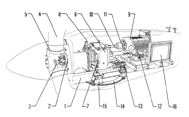
Fig. 3-29 Vestas V27-225, modular drive train; 1 nacelle frame, 2 main shaft, 3 pitch mecha-
nism, 4 rotor blade, 5 cast steel hub, 6 spur gearbox, 7 torsionally elastic gear suspension, 8
brake, 9 pole-switchable asynchronous generator, 10 fast shaft with coupling, 11sliding clutch,
12 hydraulic unit, 13 yaw drive, 14 yaw ring, 15 power cable twist control, 16 top control unit