Harris C.M., Piersol A.G. Harris Shock and vibration handbook
Подождите немного. Документ загружается.


Analogously, the time function obtained by an inverse Fourier transformation of
a one-sided spectrum (positive frequencies only) is complex, but the imaginary part
is the Hilbert transform of the real part. Such a complex time signal is known as an
analytic signal.
An analytic signal can be thought of as a rotating vector (or phasor) described by
the formula A(t)e
j φ(t)
whose amplitude A(t) and rotational speed ω(t) = dφ(t)/dt, in gen-
eral, vary with time. Analytic signals are useful in vibration studies to describe modu-
lated signals. For example, a phase-coherent signal [Eq. (22.3)] can be represented as
the real part of an analytic signal, in which case the imaginary part can be obtained by
a Hilbert transform.Therefore, from a measured time signal, a(t), it is possible to obtain
the amplitude and phase (or frequency) modulation components from the relationship
A(t)e
j φ(t)
= a(t) + jã(t) (14.12)
where ã(t) is the Hilbert transform of a(t).
The Hilbert transform may be evaluated directly from the equation
ã(t) =
∞
−∞
a(τ) dτ (14.13)
but it can be more readily evaluated by a phase shift in the frequency domain, in par-
ticular in an FFT analyzer.
16
An alternative way of generating analytic signals using
an FFT analyzer is by an inverse Fourier transformation of the equivalent one-sided
spectrum formed from the spectrum of the real part only. The time signals resulting
from the real-time zoom process (described above) automatically have the same
amplitude function A(t) as the equivalent bandpass-filtered analytic signal, since
they are obtained from the positive frequency components only (Fig. 14.16).The fre-
quency-shifting operation affects only the phase function e
j φ(t)
.
The major applications of Hilbert transform techniques in vibration studies
involve either amplitude demodulation or phase demodulation.
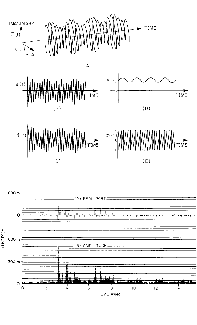
Amplitude Demodulation. Figure 14.33 shows the analytic signal for the case
of single-frequency amplitude modulation of a higher-frequency carrier component.
The imaginary part is the Hilbert transform of the real part; this manifests itself as a
90° phase lag.The amplitude function is the envelope of both the real and imaginary
parts and represents the modulating signal plus a dc offset. The phase function is a
linear function of time (whose slope represents the speed of rotation, or frequency,
of the carrier component); it is, however, shown modulo 2π, as is conventional.
One area of application of amplitude demodulation where it is advantageous to
view the signal envelope rather than the time signal itself is in the interpretation of
such oscillating time functions as autocorrelation and crosscorrelation functions
(see Chap. 22). Figure 14.34
18
shows a typical case where peaks indicating time
delays are difficult to identify in a crosscorrelation function as defined in Eq. (22.48),
because of the oscillating nature of the basic function (Fig. 14.34A). The peaks are
much more easily seen in the envelope or magnitude of the analytic signal (Fig.
14.34B). Another advantage of the analytic signal is that its magnitude can be dis-
played on a logarithmic axis; this allows low-level peaks to be detected and converts
exponential decays to straight lines.
18
Another area of application of amplitude demodulation is in envelope analysis
(discussed in Chap. 13 in the section on Envelope Detectors). In particular, when the
signal is to be bandpass-filtered before forming the envelope, this can be done by
real-time zoom in the appropriate passband. Figure 14.35 shows an example from
the same vibration source as was analyzed in Fig. 14.31. Figure 14.35A shows a typi-
cal envelope signal obtained from zooming in a 1600-Hz band centered at 3 kHz.
1
t −τ
1
π
14.38 CHAPTER FOURTEEN
8434_Harris_14_b.qxd 09/20/2001 11:12 AM Page 14.38
VIBRATION ANALYZERS AND THEIR USE 14.39
FIGURE 14.33 Analytic signal for simple amplitude modulation. (A) Analytic signal a(t) +
jã(t) = A(t)e
jφ(t)
.(B) Real part a(t). (C) Imaginary part ã(t). (D) Amplitude A(t). (E) Phase φ(t).
FIGURE 14.34 Example of a crosscorrelation function expressed as follows:
18
(A) The real part of an
analytic signal, i.e., the normal definition [Eq. (22.48)]. (B) The amplitude of the analytic signal. The
peaks corresponding to time delays are more easily seen in this representation. The signal was obtained
by bandpass filtering (using FFT zoom) in the frequency range from 512 to 13,312 Hz.
8434_Harris_14_b.qxd 09/20/2001 11:12 AM Page 14.39
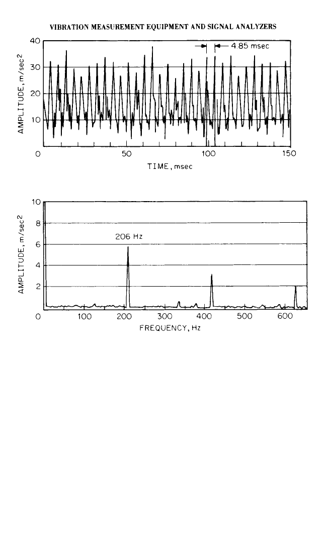
The spectrum of Fig. 14.31A shows that this frequency range is dominated by the
harmonic family which results from a fault in a bearing. Consequently, the corre-
sponding envelope signal (Fig. 14.35A) indicates a series of bursts with the same
period, 4.85 milliseconds (compare with the cepstrum of Fig. 14.31C). Figure 14.35B
shows the average spectrum of a number of such envelope signals; this gives a fur-
ther indication that the dominant periodicity is 206 Hz.
Phase Demodulation. For a purely phase-modulated signal, the amplitude
function A(t) is constant and the phase function φ(t) is given by the sum of a carrier
component of constant frequency f
c
and the modulation signal φ
m
(t). Thus
φ(t) = 2πf
c
t +φ
m
(t) (14.14)
14.40 CHAPTER FOURTEEN
FIGURE 14.35 Envelope analysis using Hilbert transform techniques. (A) Typical
envelope signal showing bursts with a period of 4.85 milliseconds from a fault in a ball
bearing. (B) Average spectrum of the envelope signal showing corresponding harmonics
of 206 Hz. Signal obtained by bandpass filtering (using FFT zoom) in the frequency range
from 2200 to 3800 Hz (compare with Fig. 14.31A, which shows a baseband analysis of this
same signal).
8434_Harris_14_b.qxd 09/20/2001 11:12 AM Page 14.40
Real-time zoom analysis centered on frequency f
0
subtracts this frequency from all
components in the signal; consequently, by zooming at the carrier frequency f
c
, only
the modulation signal φ
m
(t) remains. In general it is possible to zoom exactly at the
carrier frequency only when the latter is made to coincide exactly with an analysis
line (for example, by employing order tracking). Otherwise, the small difference in
frequency gives a residual slope to the phase signal.
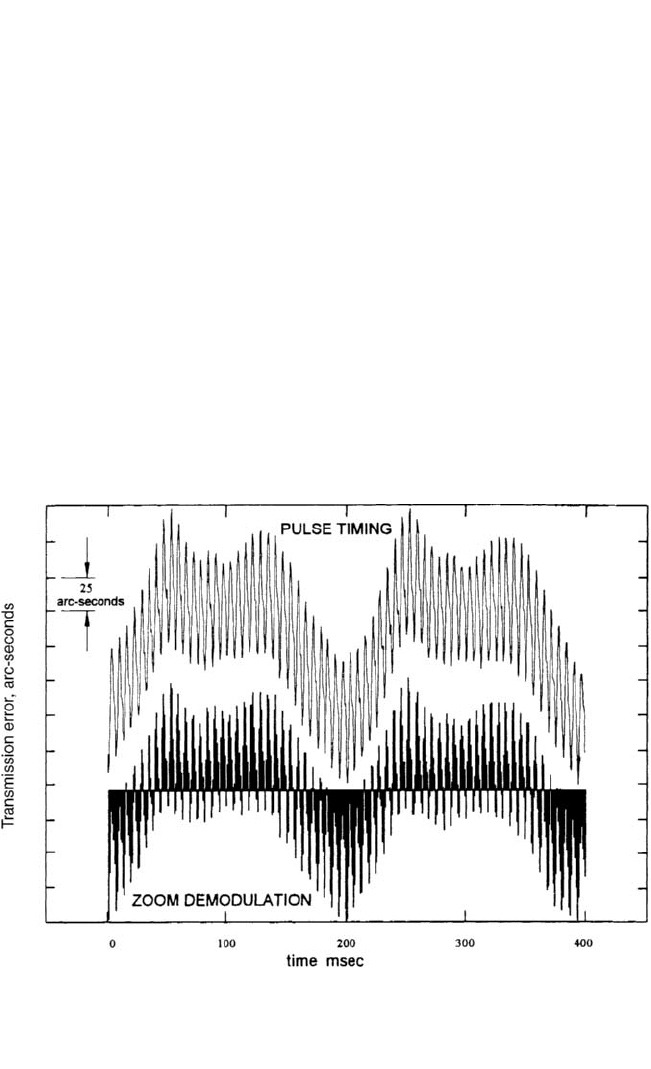
Figure 14.36 shows an example of the application of this technique to the meas-
urement of gear transmission error.
19
This can be obtained as the difference in tor-
sional vibration (i.e., phase modulation) of the two gears in mesh, after appropriate
compensation for the gear ratio (in this particular case the ratio is unity). The tor-
sional vibrations were measured by demodulating the output signals from optical
encoders attached to each shaft. The encoders give 16,000 pulses per revolution, but
this was divided down to 4000 for the results shown here (and for the zoom demod-
ulation technique even further decimation would be possible). The result obtained
by zoom demodulation, including digital tracking, was produced by an advanced
FFT analyzer, and is compared with a result obtained using a 100-MHz clock to time
the intervals between pulses and thus measure phase modulation somewhat more
directly. The two results are virtually identical, and are accurate to within a few arc-
seconds. Similar methods have been used to detect cracks in gears by amplitude and
phase demodulation of the tooth-meshing signal.
20
VIBRATION ANALYZERS AND THEIR USE 14.41
FIGURE 14.36 Gear dynamic transmission error measured using the zoom demodulation tech-
nique compared with direct measurement by timing the intervals between shaft encoder pulses.
19
Measurements were made with two 32-tooth gears, although the method is not limited to unity-ratio
gears. Note the periodic repetition once per revolution of the gears (200 milliseconds) and the higher-
frequency component corresponding to tooth-meshing.
8434_Harris_14_b.qxd 09/20/2001 11:12 AM Page 14.41

REFERENCES
1. Cooley, J. W., and J. W. Tukey: Math. Computing, 19(90):297 (1965).
2. Cooley, J. W., P. A. W. Lewis, and P. D. Welch: J. Sound Vibration, 12(3):315 (1970).
3. Brigham, E. O.: “The Fast Fourier Transform,” Prentice-Hall, Inc., Englewood Cliffs, N.J.,
1974.
4. Thrane, N.: “Zoom-FFT,” Brüel & Kjaer Tech. Rev., (2) (1980).
5. Sloane, E.A.: IEEE Trans. Audio Electroacoust., AU-17(2):133 (1969).
6. Welch, P. D.: IEEE Trans. Audio Electroacoust., AU-15(2):70 (1967).
7. Randall, R. B.: “Frequency Analysis,” Brüel & Kjaer, Naerum, Denmark, 1987.
8. Mitchell, J. S.: “An Introduction to Machinery Analysis and Monitoring,” Penwell Publish-
ing Company, Tulsa, Okla., 1981.
9. Bogert, B. P., M. J. R. Healy, and J. W. Tukey: In M. Rosenblatt (ed.), “Proceedings of the
Symposium on Time Series Analysis,” John Wiley & Sons, Inc., New York, 1963, pp.
209–243.
10. Childers, D. G., D. P. Skinner, and R. C. Kemerait: Proc. IEEE, 65(10):1428 (1977).
11. Randall, R. B.: Maintenance Management Int., 3:183 (1982/1983).
12. Oppenheim, A. V., R. W. Schafer, and T. G. Stockham Jr.: Proc. IEEE, 56(August):1264
(1968).
13. Gao, Y., and R. B. Randall: Mechanical Systems and Signal Processing, 10(3):293–317,
319–340 (1996).
14. Lyon, R. H., and A. Ordubadi: J. Mech. Des., 104(Trans. ASME)(April):303 (1982).
15. DeJong, R. G., and J. E. Manning: “Gear Noise Analysis using Modern Signal Processing
and Numerical Modeling Techniques,” SAE Paper No. 840478, 1984.
16. Papoulis, A.: “The Fourier Integral and Its Applications,” McGraw-Hill Book Company,
Inc., New York, 1962.
17. Thrane, N.: Brüel & Kjaer Tech. Rev., (3) (1984).
18. Herlufsen, H.: Brüel & Kjaer Tech. Rev., (1 and 2) (1984).
19. Sweeney, P. J., and R. B. Randall: Proc. I. Mech. E., Part C, J. Mech. Eng. Sc., 210(C3):201–213
(1996).
20. McFadden, P.: J. Vib. Acoust. Stress & Rel. Des., 108(Trans. ASME)(April):165 (1986).
14.42 CHAPTER FOURTEEN
8434_Harris_14_b.qxd 09/20/2001 11:12 AM Page 14.42

CHAPTER 15
MEASUREMENT TECHNIQUES
Cyril M. Harris
INTRODUCTION
Earlier chapters describe equipment used in vibration measurements. For example,
detailed information concerning transducers, their characteristics, and how these
characteristics are influenced by environmental factors is given in Chap. 12. The var-
ious measurement system components and the characteristics which determine their
selection are described in Chaps. 13 and 14.The use of such measurement systems in
vibration problems may involve only one or two engineers as in monitoring the con-
dition of machinery in a factory (Chap. 16), in some problems in modal testing
(Chap. 21), in measurements in building structures (Chap. 24), in measuring tor-
sional vibration in reciprocating and rotating engines (Chap. 38), and in the balanc-
ing of rotating machinery (Chap. 39). In contrast, in the aerospace industry, some
measurement problems are so complex that teams of engineers and several divisions
of the company may be involved. Yet all these examples share certain basic meas-
urement procedures. It is these basic procedures (rather than measurement details,
which vary from problem to problem) that are considered here. Thus, this chapter
includes a general discussion of (1) planning measurements to achieve stated objec-
tives, (2) selecting the type of measurements which should be made to achieve these
objectives, (3) selecting transducers, (4) mounting transducers, (5) mounting cable
and wiring (including shielding and grounding), (6) selecting techniques for the field
calibration of the overall measurement system, (7) collecting and logging the data
obtained, and (8) conducting a measurement error analysis.
The best method of analyzing the vibration measurement data, once they have
been acquired, depends on a number of factors, including the quantity of data to be
processed, the objectives of the measurements, test criteria, specifications, and the
accuracy required.These factors are discussed in Chaps. 14, 20, 22, 23, 27, and 28.
MEASUREMENT PLANNING
Careful pretest planning (and, in the case of a complex measurement program,
detailed documentation) can save much time in making measurements and in ensur-
ing that the most useful information is obtained from the test data. In many cases, as
15.1
8434_Harris_15_b.qxd 09/20/2001 11:10 AM Page 15.1

in environmental testing, measurement procedures are contained in test specifica-
tions to ensure that a specification or legal requirement has been met. In other cases
(as in balancing rotating machinery), measurement procedures are outlined in detail
in national or international standards. In general, the first step in planning is to
define the purpose of the test and to define what is to be measured. Planning should
start with a clear definition of the test objectives, including the required accuracy
and reliability. The second step is to define those non-equipment-related factors
which influence the selection of measurement equipment and measurement tech-
niques.These include availability of trained personnel; cost considerations; length of
time available for measurements; scheduling considerations; and available tech-
niques for data analysis, validation, and presentation.
Next, the various factors listed in Table 15.1 should be considered. For example,
it is important to have some estimate of the characteristics of the motion to be meas-
ured—e.g., its frequency range, amplitude, dynamic range, duration, and principal
direction of motion. Such information is needed to provide the basis for the opti-
mum selection of measurement equipment. Yet often very little is known about the
characteristics of the motion to be measured. Previous experience may provide a
guide in estimating signal characteristics. Where this is not available, preliminary
measurements may be carried out to obtain information which serves as a guide for
further measurements. For example, suppose preliminary measurements show a fre-
quency spectrum having considerable content in the region of the lowest frequency
measured. This would indicate that the instrumentation capability should be
extended to a somewhat lower frequency in subsequent measurements. Thus an iter-
ative process often takes place in a shock and vibration measurement program. To
speed this process, it is helpful to employ equipment whose characteristics cover a
wide range and which has considerable flexibility. Failure to take this feedback
process into account can sometimes result in the acquisition of meaningless test
results. For example, a measurement program was carried out by one organization
over a period of many weeks. The objective was to correlate building vibration data,
measured in the organization’s own laboratories, with the acceptability of these lab-
oratories as sites for ultrasensitive galvanometers and other motion-sensitive equip-
ment. No correlation was found, and the entire measurement program was a waste
of time, for two reasons: (a) The measurements were made with equipment with a
frequency limit which was not sufficiently low, so that important spectral compo-
nents of building vibration could not be measured. (b) Measurements were made
only in the vertical direction, whereas it was the horizontal component which was
dominant and which made certain laboratory areas unacceptable for the location of
vibration-sensitive equipment.
Many of the various factors, listed in Table 15.1, which should be considered in
planning instrumentation for shock and vibration measurements are discussed in
earlier chapters and are cross-referenced, rather than repeated, here. For example,
Chap. 12 discusses the effects of environmental conditions on transducer character-
istics; Chap. 13 describes various components which follow the transducer in a meas-
urement system (such as preamplifiers, signal conditioners, filters, analyzers, and
recorders). Chapter 14 describes the selection of the appropriate analyzer band-
width, frequency scale, amplitude scale, selection of data windows, etc.
Before making measurements, it is usually important to establish a measurement
protocol—the more complex the measurements to be made, the more formal and
detailed the measurement protocol should be. It is also important to make an error
analysis, i.e., (a) to estimate the error introduced into the data acquisition and analy-
sis by each individual item of equipment, and (b) to determine the total error by cal-
culating the square root of the sum of the squares of the individual errors. For
15.2 CHAPTER FIFTEEN
8434_Harris_15_b.qxd 09/20/2001 11:10 AM Page 15.2

TABLE 15.1 Factors Which Are Important Considerations in the Selection of Measurement
Equipment and Measurement Techniques for Mechanical Shock and Vibration Measurements
Parameter to be measured
Acceleration Strain
Velocity Force
Displacement Mechanical impedance
Characteristics of motion to be measured
Frequency range Direction of motion
Amplitude range Transient characteristics
Phase Duration
Environmental conditions
Temperature (ambient and transient) Magnetic and radio-frequency fields
Humidity Corrosive and abrasive media
Ambient pressure Nuclear radiation
Acoustic noise Sustained acceleration
Transducer characteristics (see Chap. 12)
Electrical characteristics (sensitivity, resolution, cross-axis sensitivity, amplitude linearity,
dynamic range, frequency response, phase response, effects of environment on the transducer)
Physical characteristics (e.g., size and mass)
Self-generating or auxiliary power required
Electrically grounded to case, or isolated
Self-contained amplifier
Transducer mountings and locations of mountings
Effect of mounting on transducer characteristics
Effect of mounting on vibratory characteristics of item under test
Number of measurement locations
Space availability for measurement locations
Availability of well-regulated power, free of voltage spikes
Ease of installation
Possibility of mounting misalignment with respect to intended direction of measurement
System components (preamplifiers, signal conditioners, filters, analyzers) (see Chaps. 13 and 14)
Electrical characteristics (e.g., input and output impedances)
Power availability
Noise interference (shielding, avoidance of ground loops)
Number of channels required for measurement and recording: maximum duration of
measurements, tape storage requirements
Possible requirement for real-time information
Method of data transmission
Coaxial cable
Twisted pair of wires
Telemetry (channels assigned)
Optical fiber
Recording equipment (see Chap. 13)
Recording-time capability
Electrical characteristics (e.g., signal-to-noise ratio)
Portability; power requirements
Correlation between recorded information and physical phenomena
Redundancy to minimize the risk of loss of vital information
15.3
8434_Harris_15_b.qxd 09/20/2001 11:10 AM Page 15.3

example, such an analysis may discover that an individual item of equipment is pri-
marily responsible for introducing a significant total error, suggesting that perhaps it
should be replaced. Furthermore,such a determination will indicate whether the total
error is within the bounds of acceptability, thereby avoiding useless measurements.
SELECTION OF THE PARAMETER
TO BE MEASURED
Often, the selection of the parameter to be measured (displacement, velocity, accel-
eration, or strain) is predetermined by specifications or by standards. When this is
not the case, it is often helpful to apply the considerations given in Table 15.2 or to
apply the flattest spectrum rule described in Chap. 16. According to this rule, the best
motion parameter to use is the one whose spectrum is closest to being uniform (i.e.,
the one having the flattest spectrum). This is important for two reasons: If the spec-
trum is relatively flat, then (1) an increase at any frequency has a roughly even
chance of influencing overall vibration levels, and (2) minimum demands are placed
on the required dynamic range of the equipment which follows the transducer. For
example, Fig. 16.2 shows two spectra obtained under identical conditions—one a
velocity spectrum, the other a displacement spectrum. The spectrum obtained using
a velocity transducer is the more uniform of the two; therefore, velocity would be the
appropriate motion parameter to select.
SELECTING THE TRANSDUCER
In selecting the transducer best suited for a given measurement, the various factors
listed in Table 15.1 must be taken into consideration, particularly those under
Parameter to Be Measured, Characteristics of Motion to Be Measured, Environmen-
tal Conditions, and Transducer Characteristics. Each of these factors (as well as cost
and availability) influences the selection process. If consideration of different factors
leads to recommendations which are in opposition, then the relative importance of
each factor must be determined and a decision made on this basis. For example, con-
sider two factors which enter into the selection of a piezoelectric accelerometer, sen-
sitivity and mass. Sensitivity considerations would suggest that a transducer of large
size be selected since transducer sensitivity generally increases with size (and there-
fore with mass) for an accelerometer of this type. In contrast, mass considerations
would suggest that a transducer of small size be selected in order to minimize the
mass loading on the test item; a small size is advantageous since, as Eq. (12.13) indi-
15.4 CHAPTER FIFTEEN
TABLE 15.1 Factors Which Are Important Considerations in the Selection of Measurement
Equipment and Measurement Techniques for Mechanical Shock and Vibration Measurements
(Continued)
Field calibration
Transducers
Over-all measurement system
Data analysis, presentation, and validation
Manual or automatic (Chap. 14); computer (Chaps. 22, 23, 27, and 28)
Type of presentation required
8434_Harris_15_b.qxd 09/20/2001 11:10 AM Page 15.4

cates, the natural frequency of a structure is lowered by the addition of mass. There-
fore in this case one should choose the most sensitive transducer (and therefore the
largest size) which produces no significant mass loading. In special cases, even the
smallest transducer may result in an unacceptable load. Then one of the devices
described in Chap. 12 which make no contact with the test surface may be selected.
Consider another example. Suppose a specification requires that vibration dis-
placement be measured. It is reasonable to assume that a displacement transducer
(such as the one described in Chap. 12) should be chosen since (depending on the
frequency spectrum) such a selection could yield the highest signal-to-noise ratio.
On the other hand, in many measurement problems it is more convenient and
equally satisfactory to select an accelerometer having a wide dynamic range and to
employ an electric circuit which obtains displacement by double integration of the
signal from the transducer’s output.
TRANSDUCER MOUNTINGS
Various methods of mounting a transducer on a test surface include (1) screwing the
transducer to the test surface by means of a threaded stud, (2) cementing the trans-
ducer to the test surface, (3) mounting the transducer on the test surface by means
MEASUREMENT TECHNIQUES 15.5
TABLE 15.2 A Guide for the Selection of the Parameter to Be Measured
Acceleration measurements
Used at high frequencies where acceleration measurements provide the highest signal outputs
Used where forces, loads, and stresses must be analyzed—where force is proportional to
acceleration (which is not always the case)
Used where a transducer of small size and small mass is required, since accelerometers
usually are somewhat smaller than velocity or displacement pickups
Velocity measurements
Used where vibration measurements are to be correlated with acoustic measurements since
sound pressure is proportional to the velocity of the vibrating surface
Used at intermediate frequencies where displacement measurements yield transducer
outputs which may be too small to measure conveniently
Used extensively in measurements on machinery where the velocity spectrum usually is more
uniform than either the displacement or acceleration spectra
Used where vibration measurements on resonant structures are to be correlated with modal
stress, since modal stress is proportional to modal velocity at resonance frequencies
Displacement measurements
Used where amplitude of displacement is particularly important—e.g., where vibrating parts
must not touch or where displacement beyond a given value results in equipment damage
Used where the magnitude of the displacement may be an indication of stresses to be analyzed
Used at low frequencies, where the output of accelerometers or velocity pickups may be too
small for useful measurement
Used to measure relative motion between rotating bodies and structure of a machine
Strain measurements
Used where a portion of the specimen being tested undergoes an appreciable variation in
strain caused by vibration—usually limited to low frequencies
8434_Harris_15_b.qxd 09/20/2001 11:10 AM Page 15.5