Harris C.M., Piersol A.G. Harris Shock and vibration handbook
Подождите немного. Документ загружается.


of a layer of wax, (4) attaching the transducer to a ferromagnetic surface by means
of a permanent magnet, (5) mounting the transducer on a bracket which, in turn, is
mounted on the test surface, and (6) holding the transducer against the test surface
by hand. Several of these mounting techniques are illustrated in Fig. 15.1, and their
frequency response characteristics are shown in Fig. 15.2. Two types of mechanical
brackets are illustrated in Fig. 15.3.
The method of mounting affects the resonance frequency and, hence, the useful fre-
quency range of the transducer. Therefore it is important to ensure that the frequency
response is adequate before measurements are taken. Each of the above methods of
mounting has its advantages and disadvantages. The appropriate choice for a given
measurement problem depends on a number of factors, including the following:
Effect of the mounting on the useful frequency range of the transducer
Effect of mass loading of the transducer mounting on the test surface
Maximum level of vibration the mounting can withstand
Maximum operating temperature
Measurement accuracy
Repeatability of measurements (Can the transducer be remounted at exactly the
same position with the same orientation?)
Stability of the mounting with time
Requirement that the test surface not be damaged by screw holes
Requirement for electrical insulation of the transducer
Time required for preparation of test surface
Time required to prepare mounting
Time required to remove mounting
Difficulty in cleaning the transducer after removal from test surface
Difficulty in cleaning test surface after transducer removed
Skill required to prepare mounting
Cost of mounting
Environmental problems (dirt, dust, oil, moisture)
For example, the above “requirement for electrical insulation of the transducer”
would be a major consideration in the selection of a method of mounting if the insu-
lation so obtained would result in the breaking of a ground loop, as explained in a
following section.
Stud Mounting. Figure 15.1A illustrates a typical stud-mounted transducer; the
transducer is fixed to the test surface by means of a threaded metal screw. One
method of insulating the stud-mounted transducer from the test surface is shown in
Fig. 15.1B. The metal stud is replaced with one which is fabricated of insulating
material, and a mica washer is inserted between the transducer and the test surface.
Other manufacturers employ a threaded, insulated stud with a flange made of the
same material; the flange, midway along the length of the stud, serves as the base for
the accelerometer. The entire base of the transducer should be in intimate contact
with the test surface. The mounting stud must be of the correct length, incorporating
a flange to prevent “bottoming” of the stud which may result in strain-induced
errors.
15.6 CHAPTER FIFTEEN
8434_Harris_15_b.qxd 09/20/2001 11:10 AM Page 15.6

FIGURE 15.1 Various methods of mounting a transducer on a test surface:
(A) Stud mounting; transducer
screws directly to the surface by a threaded stud. (B) Same as (A) but with a transducer insulated from test sur-
face by use of stud fabricated of insulating material and by a mica washer between the surface and transducer
.
(C) Cement mounting of a transducer; the cement bonds the transducer directly to the surface. (D) Similar to
(C), but here cement bonds the surface to a cementing stud screwed into the transducer
. (E) Transducer
mounted to surface by means of double-sided adhesive tape or disc
. (F ) Transducer mounted to surface by
means of a magnet. (Courtesy of Brüel & Kjaer.)
15.7
8434_Harris_15_b.qxd 09/20/2001 11:10 AM Page 15.7
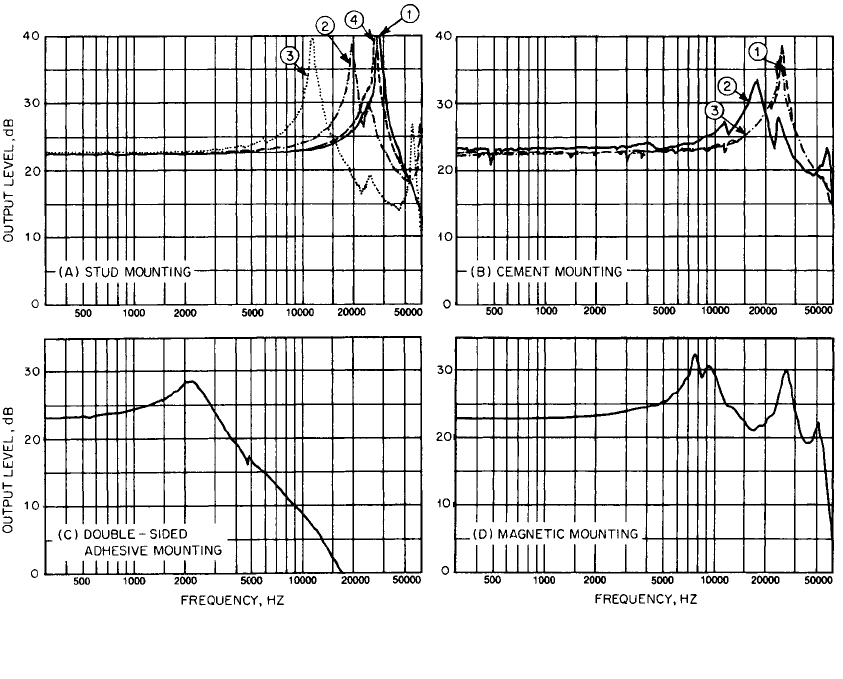
FIGURE 15.2 Frequency-response curves for the same piezoelectric accelerometer mounted by the different
methods illustrated in Fig. 15.1: (A) stud mounting; (B) cement mounting; (C) double-sided adhesive mounting;
(D) magnetic mounting. (Courtesy of Brüel & Kjaer.)
15.8
8434_Harris_15_b.qxd 09/20/2001 11:10 AM Page 15.8

Where stud mounting is practical, it is the best type to use for the following reasons:
1. It provides the highest resonance frequency (up to 100 kHz) of any of the mount-
ing techniques and, therefore, the widest possible measurement frequency range
(up to 50 kHz).
2. It permits measurements at very high vibration levels without the loosening of
the transducer from the test surface.
3. It does not reduce the maximum permissible operating temperature at which
measurements can be made.
4. It permits accurate and reproducible results since the measurement position can
always be duplicated.
In preparing a stud mounting, the test
surface must be drilled and tapped.
A standard 10-32 thread is widely
used. (Also see International Standards
Organisation Standard ISO 1101.) Dis-
tortion of the transducer as mounted
may produce strains that affect the
transducer’s response. Therefore, it is
important (1) to ensure that the test sur-
face is very flat (which can be done by
grinding or lapping), (2) to prevent the
mounting stud from bottoming in the
transducer case—this can lead to strain,
and (3) to screw the stud into the hole in the test surface, and then the accelerome-
ter onto the stud using a torque wrench to ensure repeatability in installation of the
transducers and to prevent thread damage; use the torque recommended by the
transducer’s manufacturer. The application of a silicone grease (such as Dow-
Corning DC-4) or a light machine oil between the transducer and the test surface
usually provides better response at high frequencies—say, above 2000 Hz.The upper
temperature limit for the stud mounting of Fig. 15.1A is limited only by the
accelerometer, but with the mica washer insert shown in Fig. 15.1B, the upper limit
may be as low as 480°F (250°C).
Figure 15.2A shows response curves for a stud-mounted accelerometer for the
following conditions:
➀
spanner tight, which has the highest resonance frequency,
➁
finger tight,
➂
mounted with a mica washer to provide electrical insulation between
the transducer and the vibrating surface, and
➃
mounted on a somewhat thinner
mica washer—which results in a higher resonance frequency than for
➂
.
Cement Mountings. A cement is a substance that bonds two surfaces together
when the cement hardens; it acts as an adhesive.Where it is not possible to use a stud
mounting, a transducer can be bonded to a clean test surface by means of a thin layer
of cement (for example, a cyanoacrylate, dental cement, or epoxy cement), as shown
in Fig. 15.1C. If the test surface is not flat and a miniature accelerometer is used, it
is not difficult to build up a layer of dental cement around the accelerometer so as
to provide firm attachment for the accelerometer. In mounting the transducer, it
should be pressed firmly against the flat, smooth surface to ensure that the adhe-
sive layer is thin; excess adhesive around the perimeter should then be removed
immediately.
The cement method of mounting a transducer provides excellent frequency
response, as shown in Fig. 15.2B for three conditions:
➀
accelerometer cemented
MEASUREMENT TECHNIQUES 15.9
FIGURE 15.3 Two types of mounting brack-
ets. In this example, a velocity-type transducer is
shown; the arrows indicate the direction of
sensed motion.
8434_Harris_15_b.qxd 09/20/2001 11:10 AM Page 15.9

directly to test surface,
➁
accelerometer cemented with a “soft” adhesive (not rec-
ommended), and
➂
accelerometer with a cementing stud which is cemented to the
surface with a hard cement.
This type of mounting may be used at high levels of vibration if the cementing
surfaces are carefully prepared, following the manufacturer’s instructions. Cement
mounting may or may not provide electrical insulation; if insulation is required, the
electrical resistance between the transducer and the test surface should be checked
with an ohmmeter.The maximum temperature at which measurements can be made
is limited by the physical characteristics of the cement employed—usually about
176°F (80°C), although some cements such as 3M Cyanolite 303 have an upper limit
as high as 390°F (200°C). At room temperature, it has the best coupling characteris-
tics over a wide frequency range. This type of mounting has good stability with time.
Where a transducer has been attached to a surface by the use of a cement, exercise
considerable caution in removing the transducer from the surface to avoid damag-
ing it; application of a solvent to soften the cement is strongly recommended.
Methyl cyanoacrylate cements [such as Eastman Kodak 910 (no longer available
from Eastman, but obtainable as a somewhat similar generic substitute, often with
poorer characteristics), 3M Cyanolite 101, and Permabond 747] dry much more rap-
idly than epoxy cements and therefore require less time to mount a transducer.They
may be removed easily and the surface cleaned with a solvent such as acetone.
Removal of epoxy from the test surface and from the transducer may be time-
consuming. In fact, the epoxy bond may be so good that the transducer can be dam-
aged in removing it from the test surface. When encased in epoxy, an accelerometer
may be subject to considerable strain, which will significantly alter its characteristics.
On the other hand, unless the cemented surfaces are very smooth, an epoxy can pro-
vide a superior bond since it will fill in a rough surface far better than a cyanoacry-
late cement. With either bonding agent, the surfaces must be very clean before
application of the cement. This mounting technique is not recommended for condi-
tions of prolonged high humidity or for pyroshock measurements.
Commercial adhesives are obtainable for use in very hot or in very cold environ-
ments. For cryogenic applications, a two-component epoxy resin, room-temperature-
cured, is available that is effective down to −200ºC and is able to withstand cryogenic
thermal shock without cracking. For use at very high temperatures (up to 700ºC)
ceramic-based adhesives are available that are effective, but require so high a curing
temperature that their use is usually restricted to high-temperature applications.
Several epoxy resins are commercially available that are cured at room temperature
and can operate at temperatures as high as 260ºC.
2
Wax Mounting. Beeswax or a petroleum-based petrowax may be used to attach
a transducer to a flat test surface. If the bonding layer is thin (say, no greater than 0.2
mm), it is possible to obtain a resonance frequency almost as high as that for the stud
mounting, but if the test surface is not smooth, a thicker wax layer is required and
the resonance frequency will be reduced. If the mating surfaces are very clean and
free from moisture, the transducer can be mounted fairly easily, although some prac-
tice may be required. The transducer can be removed rapidly with a naphtha-type
solvent. Disadvantages include the possibility of disattachment of the transducer at
high vibration levels, a temperature limitation because of the relatively low melting
point of wax, and poor long-time stability of the mounting. The maximum tempera-
ture at which measurements can be made with this mounting technique is usually
about 100°F (40°C).
Adhesive-Tape Mounting. An adhesive is a substance used to bond two surfaces
together. The adhesive is usually applied to a tape or disc. In such application, this
15.10 CHAPTER FIFTEEN
8434_Harris_15_b.qxd 09/20/2001 11:10 AM Page 15.10

term is often used as a synonym for the word “cement.” An adhesive film may be
used to mount a small transducer on a flat, clean test surface—usually by means of a
double-sided adhesive tape. Double-sided adhesive discs are supplied by some
transducer manufacturers.This mounting technique, illustrated in Fig. 15.1E, is rapid
and easy to apply. Furthermore, such a mounting has the advantage of providing
electrical insulation between the transducer and the test surface, and it does not
require the drilling of a hole in the test surface; it is particularly applicable for use
with a transducer having no tapped hole in its base. Such adhesives can provide
secure attachment over a limited temperature range, usually below 200°F (95°C). In
preparing an adhesive mounting, it is important to clean both the accelerometer and
the test surface so that the adhesive will adhere firmly. When this is done, the fre-
quency response can be fairly good, as illustrated in Fig. 15.2C, but not as good as
with a wax mounting.
Another method of mounting is to use a cementing stud which is threaded into
the transducer; the flat side of the stud is then cemented to the test surface as shown
in Fig. 15.1D. This is a useful technique where repeated measurements at the same
point are required. The transducer may be removed for measurements elsewhere,
but the cementing stud is left in place. This provides assurance that future measure-
ments will be made at precisely the same point.
Magnetic Mounting. With magnetic mounting, illustrated in Fig. 15.1F, a perma-
nent magnet attaches the transducer to the test surface, which must be ferromag-
netic, flat, free from dirt particles, and reasonably smooth. Magnetic mounting is
useful in measuring low acceleration levels. The transducer can be attached to the
test surface easily and moved quickly from one measurement point to another. For
example, in a condition-monitoring system (described in Chap. 16) it can be used to
determine a suitable measurement location for a transducer to be mounted per-
manently on a large rotating machine. In a heavy machine of this type, the added
mass of the magnet is not important, but in other problems, the additional mass
loading on the test surface may make the use of magnetic mounting unacceptable.
Furthermore, if the acceleration levels are sufficiently high, as in impact testing, the
magnet may become loosened momentarily. This can result in an inaccurate read-
ing and possibly a slight change in the position of the transducer, which would also
change the reading. The frequency response for this type of mounting is fair, as
shown in Fig. 15.2D, but not as good as with the wax mounting. The magnet, often
available from the transducer’s manufacturer, usually is attached to the transducer
by means of (1) a projecting screw on the magnet, which is threaded into the base
of the transducer, or (2) a machine screw, one end of which is threaded into the
transducer and the other end into the magnet.Application of a light machine oil or
silicone grease usually improves the frequency response above about 2,000 Hz.The
maximum temperature at which measurements can be made with this mounting
technique is usually about 300°F (150°C). In attaching a magnetically mounted
transducer to a test surface, the magnetic force that pulls the assembly toward the
surface may sometimes be sufficiently high to result in a high level of mechanical
shock at the time of contact, causing damage to the sensing elements or its internal
electronics.
Mounting Blocks or Brackets. Physical conditions may make it impractical to
mount a transducer by any of the above methods. In such cases, a mounting bracket
or block that has been especially prepared for use on the test surface may be
employed. For example, if the structural surface is rounded, a solid mounting block
can be fabricated which is rounded to this same contour on one side and flat on the
other side for mounting the transducer.A mounting block also may be useful where
MEASUREMENT TECHNIQUES 15.11
8434_Harris_15_b.qxd 09/20/2001 11:10 AM Page 15.11
the surface is subject to structural bending; in this case, two accelerometers selected
to have the same characteristics may be attached to the mounting block to measure
bending-induced rotation. The effect of the mass of the mounting block is consid-
ered in Eq. (15.1).Two types of mounting brackets are illustrated in Fig. 15.3. Instead
of using a triaxial accelerometer, sometimes it is more convenient to mount three
transducers on a single block having sensitivities in three orthogonal directions.Any
such mounting must couple the transducer to the test surface so that the transducer
accurately follows the motion of the surface to which it is attached.This requires that
the effective stiffness of the transducer mounting be high so that the mounting does
not deflect under the inertial load of the transducer mass. This is not a problem in
many transducer installations.
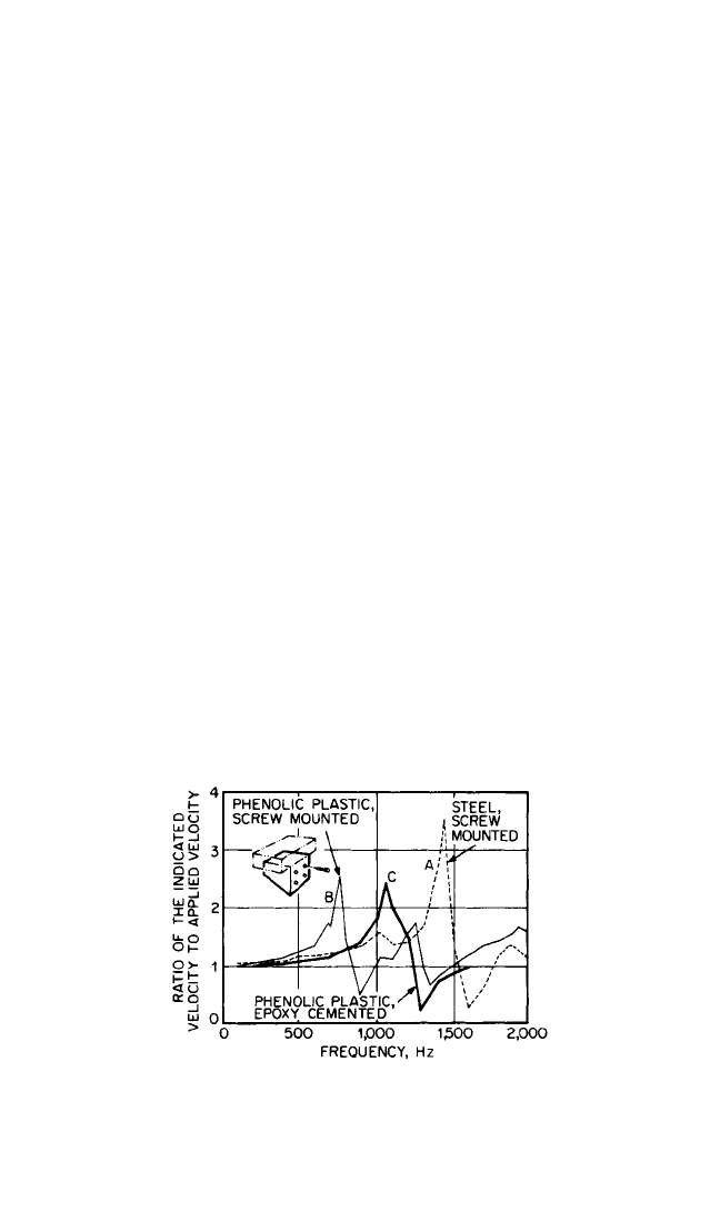
Mounting brackets may have resonance frequencies which are below 2,000 Hz
and have little damping. Under such conditions, their use may result in significant
measurement error as a result of resonant amplification or because of attenuation of
vibration in the mounting. This is illustrated in Fig. 15.4, which shows the frequency
response of a transducer mounted on brackets which are identical in geometry but
which are fabricated from different materials. Note that a change in material from
(A) steel to (B) a phenolic plastic halves the resonance frequency of the mounting.
A change in the method of attachment, from (B) screw mounting to (C) an epoxy
resin adhesive bond, significantly increases the frequency of the mounting reso-
nance. Although these results are not of a general nature, they show that such minor
variations in the transducer mounting may produce significant changes in the output
characteristics of the transducer. It is good practice to calibrate an accelerometer in
combination with its mounting block.
Hand-held Transducer. A transducer which is held against the test surface by
hand provides the poorest performance of any of the techniques described here, but
it sometimes can be useful in making a rapid survey of a test surface because the
measurement location can be changed more rapidly than with any other method of
mounting. Usually, a rod (called a probe), which is threaded at one end, is screwed
into the transducer; the other end has a tip that is pressed against the test surface.
15.12 CHAPTER FIFTEEN
FIGURE 15.4 Relative frequency response of a
velocity transducer mounted on three brackets which
have identical geometry but are fabricated of differ-
ent materials: (A) steel bracket, screw mounted, (B)
cloth-reinforced phenolic plastic bracket, screw
mounted, and (C) same as (B) but attached with
epoxy resin adhesive.
8434_Harris_15_b.qxd 09/20/2001 11:10 AM Page 15.12

The frequency response is highly restricted—about 20 to 1,000 Hz; furthermore this
technique should not be employed for accelerations greater than 1g. Thus, this tech-
nique is used when measurement accuracy is not essential, e.g., in finding the nodal
points on a vibrating surface.
Mass-Loading. The effect of the mounting on the accuracy of measurement can
be estimated roughly if it is assumed that the combination of the transducer (having
a mass m) and the mounting (having a stiffness k) behaves as a simple spring-mass
system driven at the spring end of the system. Then the acceleration of the trans-
ducer ¨x is given by
¨x = ü (15.1)
where ü is the acceleration of the test item, and f is its frequency of vibration. If the
acceleration of the transducer is to be within 10 percent of the acceleration of
the test item, then from Eq. (15.1), k must have a value at least 10 times greater than
the term m(2πf )
2
. Since the undamped natural frequency f
n
of the transducer-
mounting system is given by f
n
=
1
⁄2π(k/m)
1/2
, the value of the natural frequency of the
system must be at least 10 times the frequency of vibration of the test item—espe-
cially for the measurement of transients.
Alternatively, the unloaded dynamic environment at the mounting point can be
calculated from the measured dynamic environment using the mechanical imped-
ance ratio given by Eq. (3.4) of Ref. 2.
FIELD CALIBRATION TECHNIQUES
TRANSDUCERS
Various methods of calibrating transducers are described in Chap. 18. If a transducer
is to be used under unusual temperature conditions, it is important to perform the
calibration in the temperature range in which it will operate. Of these, the following
are particularly convenient for use in the field.
Comparison Method. This is a rapid and convenient method of obtaining the
sensitivity of a transducer. It is one of the most commonly used calibration tech-
niques. Calibration is obtained by a direct comparison of the output generated when
the transducer is attached to a vibration exciter with the output generated by a sec-
ondary standard transducer which is attached to the same vibration exciter and
which is subject to precisely the same motion. The two transducers are mounted
back to back, as illustrated in Fig. 18.3. Calibration by this method is limited to the
frequency and amplitude ranges for which the secondary standard has been cali-
brated and for which the vibration exciter has adequate rectilinear motion. The sec-
ondary standard accelerometer should be calibrated against a National Institute of
Standards and Technology (NIST) traceable reference, at least once a year, in com-
pliance with MIL-STD-45662A.
Free-fall Calibration Method. The gravimetric free-fall calibration method
(sometimes called a drop test) is a simple and rapid method of calibrating motion
and force sensors. The transducer under test is allowed to fall freely for an instant of
k
k + m(2πf )
2
MEASUREMENT TECHNIQUES 15.13
8434_Harris_15_b.qxd 09/20/2001 11:10 AM Page 15.13
time under the influence of gravity; the peak signal then is measured for an acceler-
ation of gravity having a value of 1g. This technique is illustrated in Fig. 18.5.
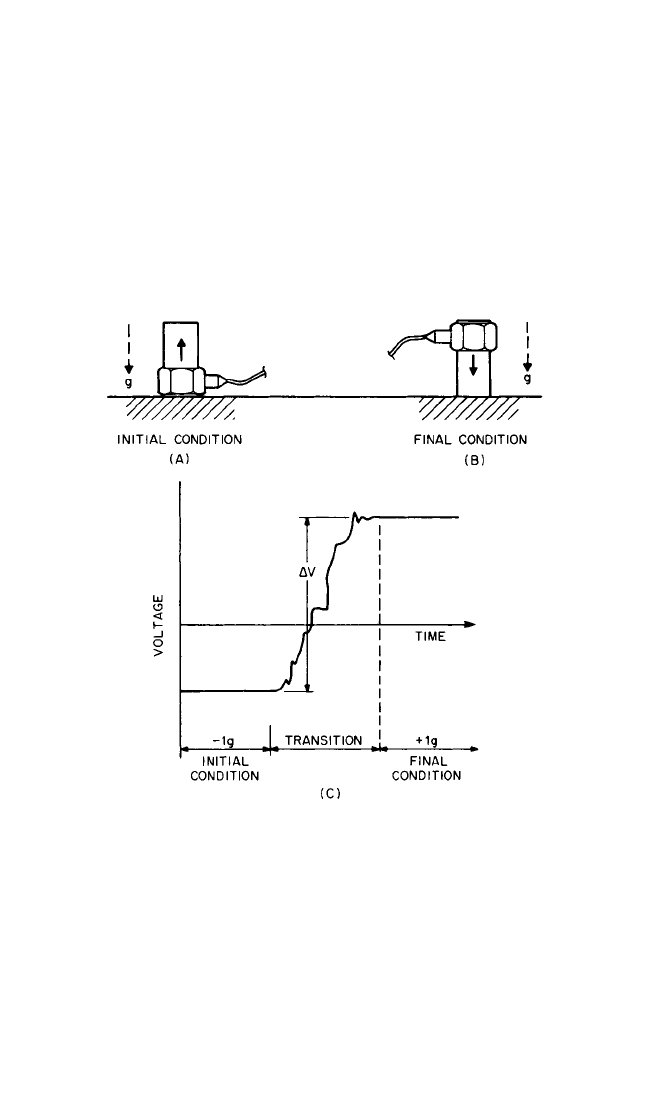
Earth’s Gravitational Field Method. In the following technique (sometimes
called the “inversion method” of calibration), the sensitive axis of the transducer is
first aligned vertically in one direction of the earth’s gravitational field, as shown in
Fig. 15.5A. Then it is inverted so that its sensitive axis is aligned in the opposite direc-
tion, as shown in Fig. 15.5B. The transducer output is observed for a 2g change in
acceleration, as shown in Fig. 15.5C. This method is limited in application to
accelerometers having sensitivity down to 0 Hz; it is not recommended for calibra-
tion of accelerometers having significant transverse sensitivity.
15.14 CHAPTER FIFTEEN
FIGURE 15.5 Gravitational field method (inversion test) for cal-
ibrating an accelerometer having useful sensitivity down to 0 Hz.
Inversion of the accelerometer, initially aligned in one direction, as
in (A), to the opposite direction, as in (B), produces a change in
acceleration of 2g. The transducer output for this change is meas-
ured in (C). (Courtesy of Quixote Measurement Dynamics, Inc.)
OVERALL SYSTEM
Calibration of a complete vibration measurement system usually is referred to as
overall calibration or end-to-end calibration. It is good practice to perform such a cal-
ibration at periodic intervals—particularly both before and after an extensive series
of measurements. In such a calibration, the amplitude characteristics, phase charac-
teristics, and linearity of the overall system are determined when the transducer is
8434_Harris_15_b.qxd 09/20/2001 11:10 AM Page 15.14
subject to a known acceleration, velocity, or displacement, for example, by means of
a field calibrator.
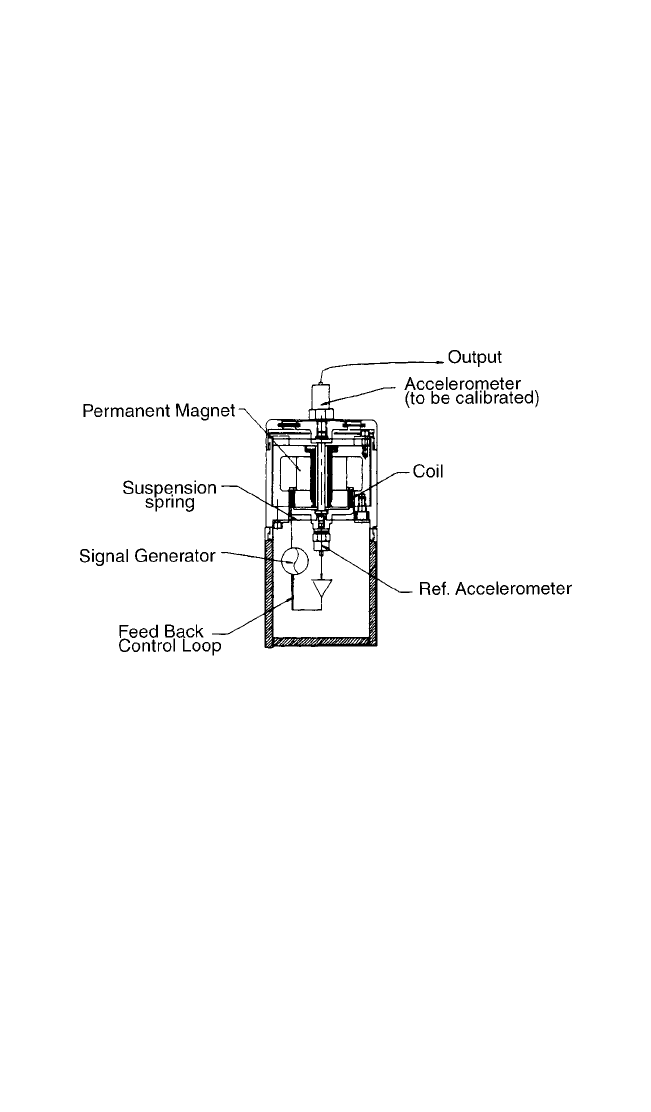
Field Calibrator. This is a portable device on which a transducer can be mounted
and subjected to a known acceleration, velocity, or displacement at a fixed fre-
quency. Such an instrument (essentially a small, portable, battery-powered shaker)
provides a convenient means for calibrating a transducer in the field and/or cali-
brating the overall vibration measurement system. For example, the hand-held
device shown in Fig. 15.6 can be used to calibrate a transducer weighing up to 85
grams at a frequency of 79.6 Hz. This device is furnished with an internal oscillator
and a stable, built-in reference accelerometer in a feedback loop controlling the
electrodynamic exciter; the exciter subjects the transducer under test to a constant
rms acceleration amplitude of 1g.
MEASUREMENT TECHNIQUES 15.15
FIGURE 15.6 A hand-held vibration calibrator especially designed for
field application. (Courtesy PCB Piezotronics, Inc.)
Combining Characteristics of Individual Components. When it is not possible
to subject the transducer to a known acceleration, velocity, or displacement, the
overall characteristics sometimes are determined by combining the characteristics
of the individual components of the system, as described below, or the system is cal-
ibrated employing a simulated transducer output [see Voltage Substitution Method
of Calibration below, and Calibration of Auxiliary Circuits (Chap. 18)].
There may be a significant electrical signal at the output of a measurement sys-
tem though no signal is supplied by the transducer to the input; such electrical sig-
nals, which represent noise, (1) may result from a coupling between circuits in the
measurement system with power circuits, (2) may be generated by vibration-
sensitive elements (such as cable) other than the transducer, or (3) may be the result
of improper selection of system components, or the improper setting of one or more
of these components, so that the signal-to-noise ratio that the overall system is capa-
ble of attaining is not achieved.
Where a single component of a measurement system is the source of noise, it can
sometimes be located by using an oscilloscope which is first connected to the trans-
ducer output with no vibration applied. Then the oscilloscope connection is moved,
component by component, through the measurement system until the noise is
8434_Harris_15_b.qxd 09/20/2001 11:10 AM Page 15.15