Heinrich J.G., Aldinger F. (Eds.) Ceramic Materials and Components for Engines
Подождите немного. Документ загружается.

99.9-
s
\
0.lL
I
‘1
‘
I
‘-I
4.8
4.9
5
5.1
5.2
(-1/2)lna
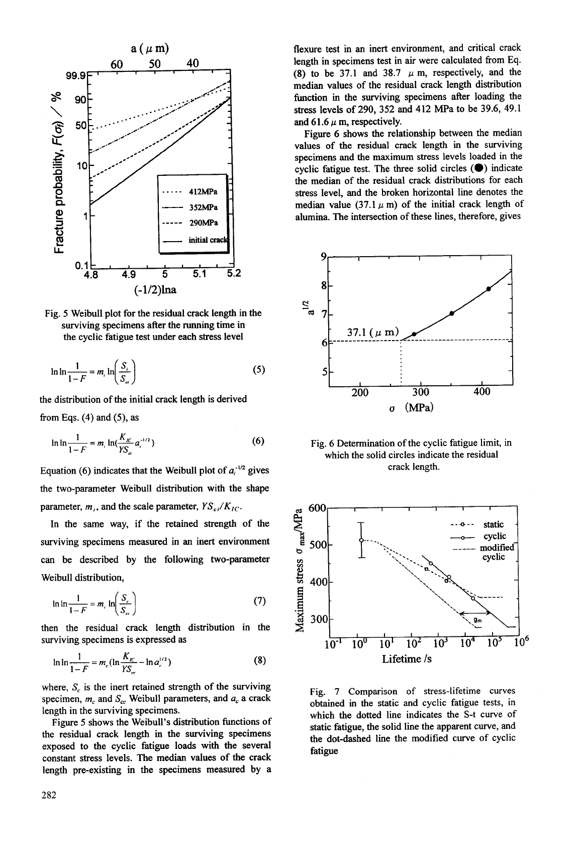
Fig.
5
Weibull plot for the residual crack length in the
surviving specimens after the running time in
the cyclic fatigue test under each stress level
Inln-=m,
1
In(?)
1-
F
the distribution of the initial crack length is derived
from Eqs.
(4)
and
(9,
as
Equation (6) indicates that the Weibull plot of
u;’”
gives
the two-parameter Weibull distribution with the shape
parameter,
m,,
and the scale parameter,
YS,,/K,,.
In the same way, if the retained strength of the
surviving specimens measured in an inert environment
can be described by the following two-parameter
Weibull distribution,
(7)
then the residual crack length distribution in the
surviving specimens is expressed
as
where,
S,
is the inert retained strzngth of the surviving
specimen,
m,
and
S,,
Weibull parameters, and
a,
a crack
length in the surviving specimens.
Figure
5
shows the Weibull’s distribution functions of
the residual crack length in the surviving specimens
exposed to the cyclic fatigue loads with the several
constant stress levels. The median values of the crack
length pre-existing in the specimens measured by a
flexure test
in
an inert environment, and critical crack
length in specimens test in air were calculated from Eq.
(8)
to be 37.1 and 38.7
p
m, respectively, and the
median values of the residual crack length distribution
function in the surviving specimens after loading the
stress levels
of
290, 352 and 412 MPa to be 39.6, 49.1
and
6
1.6
p
m, respectively.
Figure
6
shows the relationship between the median
values of the residual crack length in the surviving
specimens and the maximum stress levels loaded in the
cyclic fatigue test. The three solid circles
(0)
indicate
the median of the residual crack distributions for each
stress level, and the broken horizontal line denotes the
median value (37.1
,u
m) of the initial crack length of
alumina. The intersection of these lines, therefore, gives
s1
d
Fig. 6 Determination of the cyclic fatigue limit, in
which the solid circles indicate the residual
crack length.
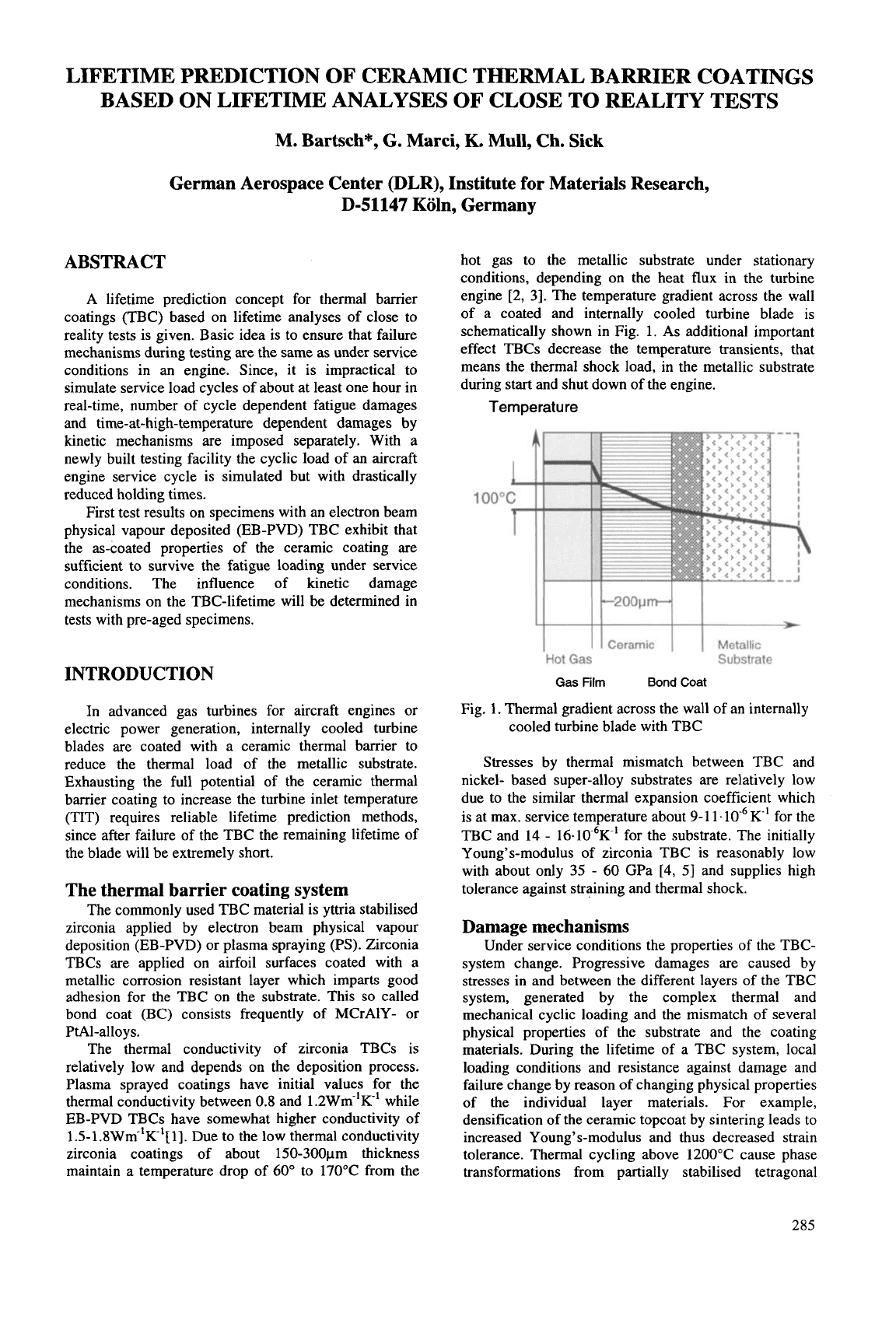
Fig.
7
Comparison of stress-lifetime curves
obtained in the static and cyclic fatigue tests, in
which the dotted line indicates the S-t curve of
static fatigue, the solid line the apparent curve, and
the dot-dashed line the modified curve of cyclic
fatigue
282
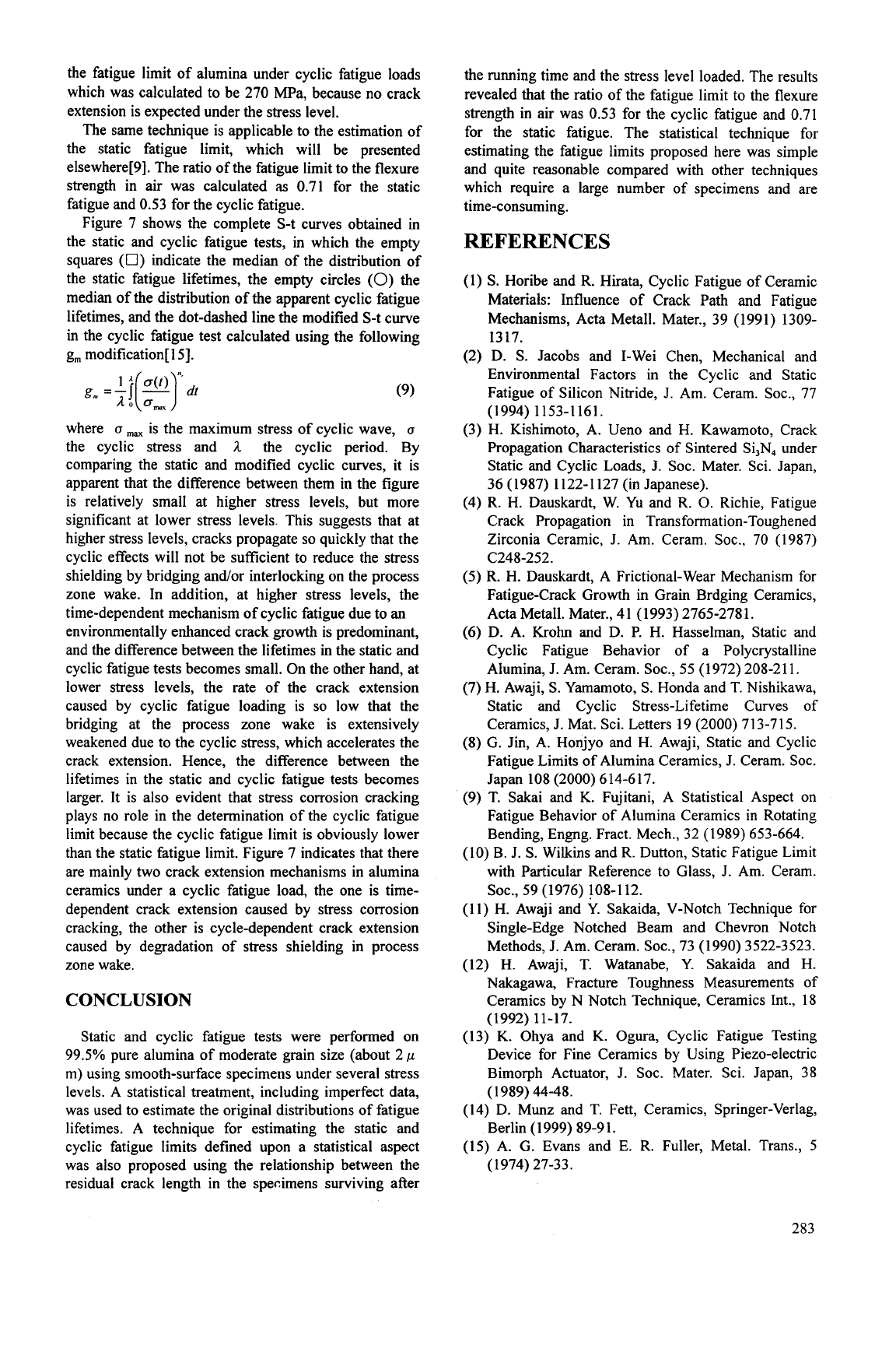
the fatigue limit of alumina under cyclic fatigue loads
which was calculated to be
270
MPa, because no crack
extension is expected under the stress level.
The same technique is applicable to the estimation of
the static fatigue limit, which will be presented
elsewhere[9]. The ratio of the fatigue limit to the flexure
strength in air was calculated
as
0.71 for the static
fatigue and 0.53 for the cyclic fatigue.
Figure 7 shows the complete S-t curves obtained in
the static and cyclic fatigue tests, in which the empty
squares
(0)
indicate the median of the distribution of
the static fatigue lifetimes, the empty circles
(0)
the
median of the distribution of the apparent cyclic fatigue
lifetimes, and the dot-dashed line the modified S-t curve
in the cyclic fatigue test calculated using the following
g, modification[ 151.
(9)
where
u
max
is the maximum stress of cyclic wave,
u
the cyclic stress and
;1
the cyclic period. By
comparing the static and modified cyclic curves, it is
apparent that the difference between them in the figure
is relatively small at higher stress levels, but more
significant at lower stress levels. This suggests that at
higher stress levels, cracks propagate
so
quickly that the
cyclic effects will not be sufficient to reduce the stress
shielding by bridging and/or interlocking on the process
zone wake. In addition, at higher stress levels, the
time-dependent mechanism of cyclic fatigue due to an
environmentally enhanced crack growth is predominant,
and the difference between the lifetimes in the static and
cyclic fatigue tests becomes small. On the other hand, at
lower stress levels, the rate of the crack extension
caused by cyclic fatigue loading is
so
low that the
bridging at the process zone wake is extensively
weakened due to the cyclic stress, which accelerates the
crack extension. Hence, the difference between the
lifetimes in the static and cyclic fatigue tests becomes
larger. It is also evident that stress corrosion cracking
plays no role in the determination of the cyclic fatigue
limit because the cyclic fatigue limit is obviously lower
than the static fatigue limit. Figure 7 indicates that there
are mainly two crack extension mechanisms in alumina
ceramics under a cyclic fatigue load, the one is time-
dependent crack extension caused by stress corrosion
cracking, the other is cycle-dependent crack extension
caused by degradation of stress shielding in process
zone wake.
CONCLUSION
Static and cyclic fatigue tests were performed on
99.5% pure alumina of moderate grain size (about 2
p
m)
using smooth-surface specimens under several stress
levels.
A
statistical treatment, including imperfect data,
was used to estimate the original distributions of fatigue
lifetimes.
A
technique for estimating the static and
cyclic fatigue limits defined upon a statistical aspect
was also proposed using the relationship between the
residual crack length in the specimens surviving after
the running time and the stress level loaded. The results
revealed that the ratio of the fatigue limit to the flexure
strength in air was 0.53 for the cyclic fatigue and 0.71
for the static fatigue. The statistical technique for
estimating the fatigue limits proposed here was simple
and quite reasonable compared with other techniques
which require a large number of specimens and are
time-consuming.
REFERENCES
(1)
S.
Horibe and R. Hirata, Cyclic Fatigue of Ceramic
Materials: Influence of Crack Path and Fatigue
Mechanisms, Acta Metall. Mater., 39 (1991) 1309-
1317.
(2) D.
S.
Jacobs and Lwei Chen, Mechanical and
Environmental Factors in the Cyclic and Static
Fatigue of Silicon Nitride,
J.
Am. Ceram. SOC., 77
(3) H. Kishimoto, A. Ueno and H. Kawamoto, Crack
Propagation Characteristics of Sintered Si,N, under
Static and Cyclic Loads, 3. SOC. Mater. Sci. Japan,
36 (1987) 1122-1127 (in Japanese).
(4) R. H. Dauskardt, W. Yu and R.
0.
Richie, Fatigue
Crack Propagation in Transformation-Toughened
Zirconia Ceramic, J. Am. Ceram. SOC., 70 (1987)
(5)
R.
H. Dauskardt, A Frictional-Wear Mechanism for
Fatigue-Crack Growth in Grain Brdging Ceramics,
Acta Metall. Mater., 4 1
(1
993) 2765-278 1.
(6)
D. A. Krohn and D. P.
H.
Hasselman, Static and
Cyclic Fatigue Behavior of a Polycrystalline
Alumina, J. Am. Ceram. SOC.,
55
(1972) 208-211.
(7)
H.
Awaji,
S.
Yamamoto,
S.
Honda and T. Nishikawa,
Static and Cyclic Stress-Lifetime Curves
of
Ceramics,
J.
Mat. Sci. Letters 19 (2000) 713-715.
(8)
G.
Jin, A. Honjyo and H. Awaji, Static and Cyclic
Fatigue Limits of Alumina Ceramics, J. Ceram. SOC.
Japan 108 (2000) 614-617.
(9) T. Sakai and K. Fujitani,
A
Statistical Aspect on
Fatigue Behavior of Alumina Ceramics in Rotating
Bending, Engng. Fract. Mech., 32 (1989) 653-664.
(10) B. J.
S.
Wilkins and
R.
Dutton, Static Fatigue Limit
with Particular Reference to Glass, J. Am. Ceram.
(1
1)
H.
Awaji and Y. Sakaida, V-Notch Technique for
Single-Edge Notched Beam and Chevron Notch
Methods, J. Am. Ceram. SOC., 73 (1990) 3522-3523.
(12)
H.
Awaji, T. Watanabe,
Y.
Sakaida and
H.
Nakagawa, Fracture Toughness Measurements
of
Ceramics by N Notch Technique, Ceramics Int., 18
(13)
K.
Ohya and K. Ogura, Cyclic Fatigue Testing
Device for Fine Ceramics by Using Piezo-electric
Bimorph Actuator, J. SOC. Mater. Sci. Japan, 38
(14) D. Munz and T. Fett, Ceramics, Springer-Verlag,
(15)
A. G. Evans and E. R. Fuller, Metal. Trans.,
5
(
1
994) 1
1
53-
1
1 6
1
.
C248-252.
SOC., 59 (1976) 108-112.
(1992) 11-17.
(1989) 44-48.
Berlin
(1
999) 89-9
1.
(1974) 27-33.
283

This Page Intentionally Left Blank
LIFETIME PREDICTION OF CERAMIC THERMAL BARRIER COATINGS
BASED ON LIFETIME ANALYSES OF CLOSE TO REALITY TESTS
M.
Bartsch",
G.
Marci,
K.
Mull, Ch. Sick
German Aerospace Center (DLR), Institute for Materials Research,
D-51147
Koln, Germany
ABSTRACT
A lifetime prediction concept for thermal barrier
coatings (TBC) based on lifetime analyses of close to
reality tests is given. Basic idea is to ensure that failure
mechanisms during testing are the same as under service
conditions in an engine. Since, it is impractical to
simulate service load cycles of about at least one hour in
real-time, number of cycle dependent fatigue damages
and time-at-high-temperature dependent damages by
kinetic mechanisms are imposed separately. With a
newly built testing facility the cyclic load of an aircraft
engine service cycle is simulated but with drastically
reduced holding times.
First test results on specimens with an electron beam
physical vapour deposited (EB-PVD) TBC exhibit that
the as-coated properties of the ceramic coating are
sufficient to survive the fatigue loading under service
conditions. The influence of kinetic damage
mechanisms on the TBC-lifetime will be determined in
tests with pre-aged specimens.
INTRODUCTION
In advanced gas turbines for aircraft engines
or
electric power generation, internally cooled turbine
blades are coated with
a
ceramic thermal barrier to
reduce the thermal load of the metallic substrate.
Exhausting the full potential of the ceramic thermal
barrier coating to increase the turbine inlet temperature
(TIT) requires reliable lifetime prediction methods,
since after failure of the TBC the remaining lifetime of
the blade will be extremely short.
The thermal barrier coating system
The commonly used TBC material is yttria stabilised
zirconia applied by electron beam physical vapour
deposition (EB-PVD) or plasma spraying (PS). Zirconia
TBCs are applied on airfoil surfaces coated with a
metallic corrosion resistant layer which imparts good
adhesion for the TBC on the substrate. This
so
called
bond coat (BC) consists frequently of MCrAlY- or
PtA1-alloys.
The thermal conductivity of zirconia TBCs is
relatively low and depends on the deposition process.
Plasma sprayed coatings have initial values for the
thermal conductivity between
0.8
and 1.2Wm-'K-' while
EB-PVD TBCs have somewhat higher conductivity of
1.5-1.8Wm-'R1[1]. Due to the low thermal conductivity
zirconia coatings of about 150-300pm thickness
maintain a temperature drop of 60" to 17OOC from the
hot gas to the metallic substrate under stationary
conditions, depending on the heat flux in the turbine
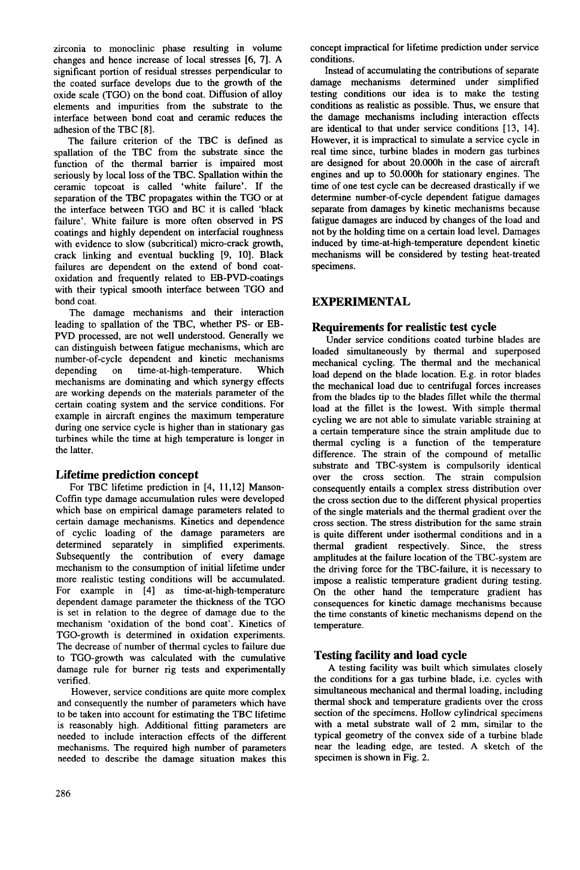
engine [2, 31. The temperature gradient across the wall
of a coated and internally cooled turbine blade is
schematically shown in Fig. 1. As additional important
effect TBCs decrease the temperature transients, that
means the thermal shock load,
in
the metallic substrate
during start and shut down of the engine.
Temperature
L
100°C
r
Ceramic Metallic
..
Hot
Gas
Substrate
Gas
Film
Bond
Coat
Fig. 1. Thermal gradient across the wall of an internally
cooled turbine blade with TBC
Stresses by thermal mismatch between TBC and
nickel- based super-alloy substrates are relatively low
due to the similar thermal expansion coefficient which
is at max. service temperature about 9-1 1.
K1
for the
TBC and 14
-
16.10-6K-' for the substrate. The initially
Young's-modulus
of
zirconia TBC is reasonably low
with about only 35
-
60 GPa
[4,
51
and supplies high
tolerance against straining and thermal shock.
Damage mechanisms
Under service conditions the properties of the TBC-
system change. Progressive damages are caused by
stresses in and between the different layers
of
the TBC
system, generated by the complex thermal and
mechanical cyclic loading and the mismatch of several
physical properties of the substrate and the coating
materials. During the lifetime of a TBC system, local
loading conditions and resistance against damage and
failure change by reason of changing physical properties
of the individual layer materials. For example,
densification of the ceramic topcoat by sintering leads to
increased Young's-modulus and thus decreased strain
tolerance. Thermal cycling above 1200°C cause phase
transformations from partially stabilised tetragonal
285
zirconia to monoclinic phase resulting in volume
changes and hence increase of local stresses
[6,
71.
A
significant portion of residual stresses perpendicular to
the coated surface develops due to the growth of the
oxide scale (TGO) on the bond coat. Diffusion of alloy
elements and impurities from the substrate to the
interface between bond coat and ceramic reduces the
adhesion of the TBC [8].
The failure criterion of the TBC is defined as
spallation of the TBC from the substrate since the
function of the thermal barrier is impaired most
seriously by local
loss
of the TBC. Spallation within the
ceramic topcoat is called ‘white failure’. If the
separation of the TBC propagates within the TGO or at
the interface between TGO and BC it is called ‘black
failure’. White failure is more often observed in PS
coatings and highly dependent on interfacial roughness
with evidence to slow (subcritical) micro-crack growth,
crack linking and eventual buckling
[9,
lo]. Black
failures are dependent on the extend of bond coat-
oxidation and frequently related to EB-PVD-coatings
with their typical smooth interface between TGO and
bond coat.
The damage mechanisms and their interaction
leading to spallation of the TBC, whether
PS-
or EB-
PVD processed, are not well understood. Generally we
can distinguish between fatigue mechanisms, which are
number-of-cycle dependent and kinetic mechanisms
depending on time-at-high-temperature. Which
mechanisms are dominating and which synergy effects
are working depends on the materials parameter of the
certain coating system and the service conditions. For
example in aircraft engines the maximum temperature
during one service cycle is higher than in stationary gas
turbines while the time at high temperature is longer in
the latter.
Lifetime prediction concept
For TBC lifetime prediction in [4, 11,121 Manson-
Coffin type damage accumulation rules were developed
which base on empirical damage parameters related to
certain damage mechanisms. Kinetics and dependence
of cyclic loading of the damage parameters are
determined separately in simplified experiments.
Subsequently the contribution of every damage
mechanism to the consumption of initial lifetime under
more realistic testing conditions will be accumulated.
For example
in
[4] as time-at-high-temperature
dependent damage parameter the thickness of the TGO
is set in relation to the degree of damage due to the
mechanism ‘oxidation of the bond coat’. Kinetics of
TGO-growth is determined in oxidation experiments.
The decrease of number of thermal cycles to failure due
to TGO-growth was calculated with the cumulative
damage rule for burner rig tests and experimentally
verified.
However, service conditions are quite more complex
and consequently the number of parameters which have
to be taken into account for estimating the TBC lifetime
is reasonably high. Additional fitting parameters are
needed to include interaction effects of the different
mechanisms. The required high number of parameters
needed to describe the damage situation makes this
concept impractical for lifetime prediction under service
conditions.
Instead of accumulating the contributions of separate
damage mechanisms determined under simplified
testing conditions our idea is to make the testing
conditions as realistic as possible. Thus, we ensure that
the damage mechanisms including interaction effects
are identical to that under service conditions [13, 141.
However, it is impractical to simulate a service cycle in
real time since, turbine blades in modern gas turbines
are designed for about 20.000h in the case of aircraft
engines and up to 50.000h for stationary engines. The
time
of
one test cycle can be decreased drastically if we
determine number-of-cycle dependent fatigue damages
separate from damages by kinetic mechanisms because
fatigue damages
are
induced by changes of the load and
not by the holding time
on
a certain load level. Damages
induced by time-at-high-temperature dependent kinetic
mechanisms will be considered by testing heat-treated
specimens.
EXPERIMENTAL
Requirements for realistic test cycle
Under service conditions coated turbine blades are
loaded simultaneously by thermal and superposed
mechanical cycling. The thermal and the mechanical
load depend on the blade location. E.g. in rotor blades
the mechanical load due to centrifugal forces increases
from
the
blades tip
to
the blades fillet while the thermal
load at the fillet is the lowest. With simple thermal
cycling we are not able
to
simulate variable straining at
a certain temperature since the strain amplitude due to
thermal cycling is a function of the temperature
difference. The strain of the compound of metallic
substrate and TBC-system is compulsorily identical
over the cross section. The strain compulsion
consequently entails a complex stress distribution over
the cross section due to the different physical properties
of the single materials and the thermal gradient over the
cross section. The stress distribution for the same strain
is quite different under isothermal conditions and in a
thermal gradient respectively. Since, the stress
amplitudes at the failure location of the TBC-system are
the driving force for the TBC-failure, it is necessary to
impose a realistic temperature gradient during testing.
On the other hand the temperature gradient has
consequences for kinetic damage mechanisms because
the time constants of kinetic mechanisms depend on the
temperature.
Testing facility and load cycle
A testing facility was built which simulates closely
the conditions for a gas turbine blade, i.e. cycles with
simultaneous mechanical and thermal loading, including
thermal shock and temperature gradients over the cross
section of the specimens. Hollow cylindrical specimens
with a metal substrate wall of 2 mm, similar to the
typical geometry of the convex side of a turbine blade
near the leading edge, are tested.
A
sketch of the
specimen is shown in Fig.
2.
286
M14x1
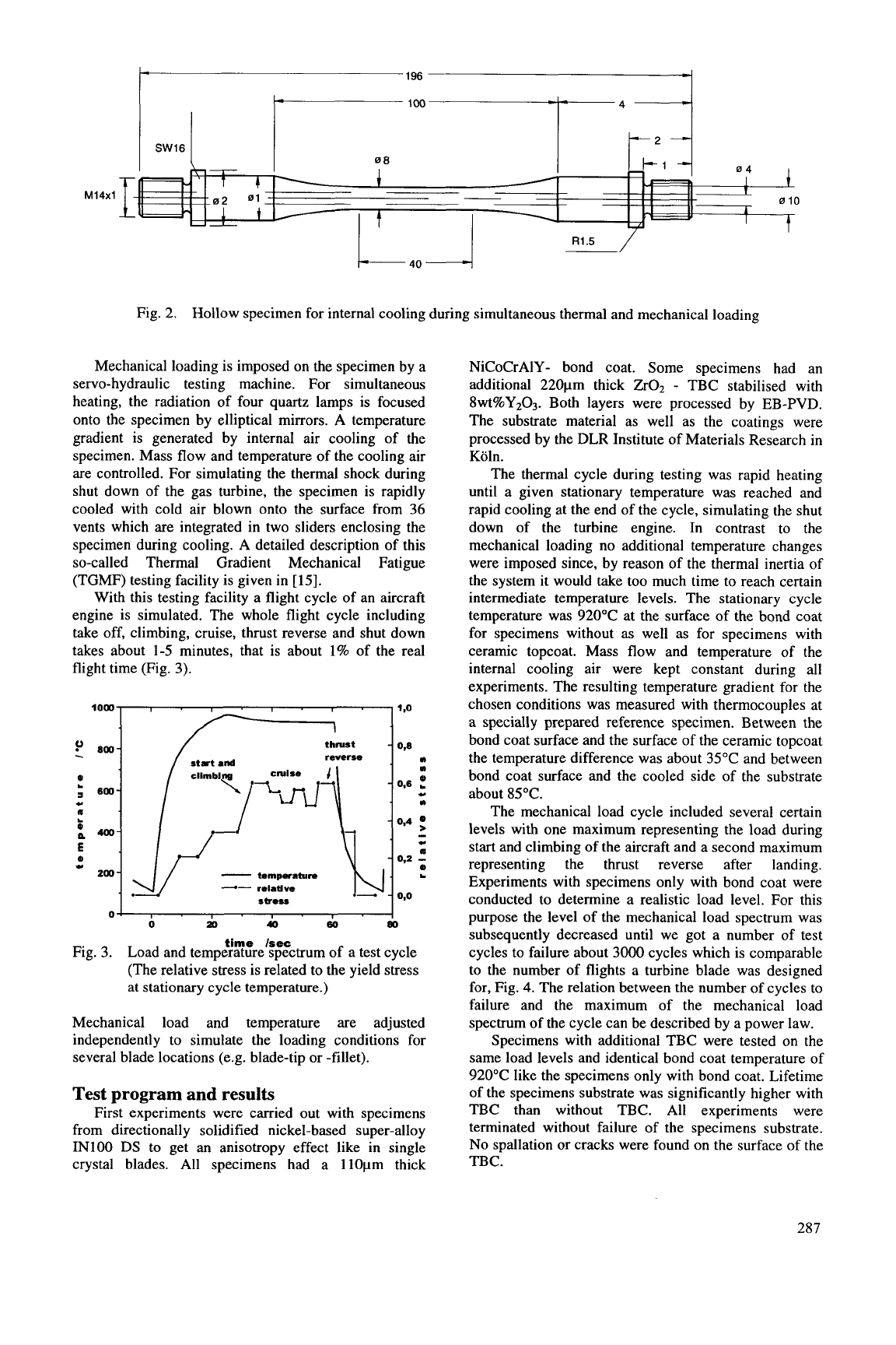
Fig.
2.
Hollow specimen for internal cooling during simultaneous thermal and mechanical loading
Mechanical loading is imposed on the specimen by a
servo-hydraulic testing machine. For simultaneous
heating, the radiation of four quartz lamps is focused
onto the specimen by elliptical mirrors.
A
temperature
gradient is generated by internal air cooling of the
specimen. Mass flow and temperature of the cooling air
are controlled. For simulating the thermal shock during
shut down of the gas turbine, the specimen is rapidly
cooled with cold air blown onto the surface from
36
vents which are integrated in two sliders enclosing the
specimen during cooling.
A
detailed description of this
so-called Thermal Gradient Mechanical Fatigue
(TGMF) testing facility is given in
[
151.
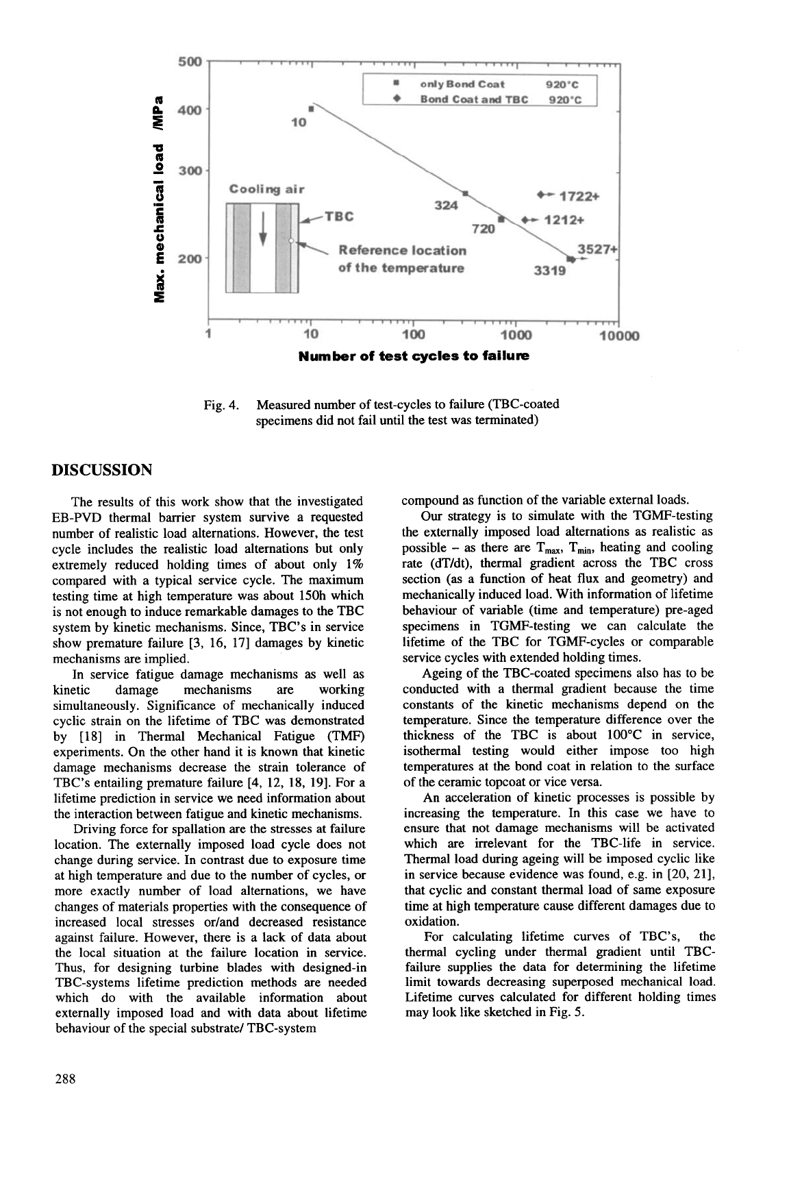
With this testing facility a flight cycle of an aircraft
engine is simulated. The whole flight cycle including
take off, climbing, cruise, thrust reverse and shut down
takes about 1-5 minutes, that is about
1%
of the real
flight time (Fig. 3).
-
tempwature
,JJ
--
relative
rbeu
-
0
do
io
w
i
Fig. 3. Load and temperature spectrum of a test cycle
(The relative stress is related to the yield stress
at stationary cycle temperature.)
time
lsec
Mechanical load and temperature are adjusted
independently to simulate the loading conditions for
several blade locations (e.g. blade-tip
or
-fillet).
Test
program
and
results
First experiments were carried out with specimens
from directionally solidified nickel-based super-alloy
IN100
DS
to get an anisotropy effect like in single
crystal blades. All specimens had a llOpm thick
NiCoCrAIY- bond coat. Some specimens had an
additional 220pm thick
ZrOz
-
TBC stabilised with
8wt%Y203.
Both layers were processed by EB-PVD.
The substrate material as well as the coatings were
processed by the DLR Institute of Materials Research
in
Koln.
The thermal cycle during testing was rapid heating
until a given stationary temperature was reached and
rapid cooling at the end of the cycle, simulating the shut
down of the turbine engine. In contrast to the
mechanical loading no additional temperature changes
were imposed since, by reason of the thermal inertia of
the system it would take too much time to reach certain
intermediate temperature levels. The stationary cycle
temperature was 920°C at the surface of the bond coat
for specimens without as well as for specimens with
ceramic topcoat. Mass flow and temperature of the
internal cooling air were kept constant during all
experiments. The resulting temperature gradient for the
chosen conditions was measured with thermocouples at
a specially prepared reference specimen. Between the
bond coat surface and the surface of the ceramic topcoat
the temperature difference was about 35°C and between
bond coat surface and the cooled side of the substrate
about 85°C.
The mechanical load cycle included several certain
levels with one maximum representing the load during
start and climbing of the aircraft and a second maximum
representing the thrust reverse after landing.
Experiments with specimens only with bond coat were
conducted to determine a realistic load level. For this
purpose the level of the mechanical load spectrum was
subsequently decreased until we got a number of test
cycles to failure about
3000
cycles which is comparable
to the number of flights a turbine blade was designed
for, Fig.
4.
The relation between the number
of
cycles to
failure and the maximum of the mechanical load
spectrum of the cycle can be described by a power law.
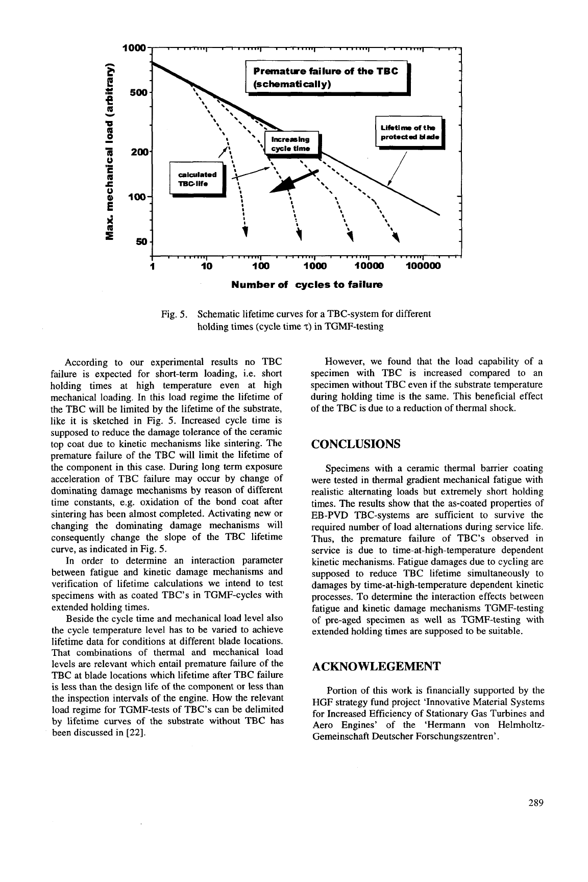
Specimens with additional TBC were tested on the
same load levels and identical bond coat temperature of
920°C like the specimens only with bond coat. Lifetime
of the specimens substrate was significantly higher with
TBC than without TBC. All experiments were
terminated without failure of the specimens substrate.
No
spallation
or
cracks were found on the surface of the
TBC.
287
I
I
I
I
onlyBondCoat 920-c
+
BondCogtandTBC 92O’C
m\
Cooling
air
+--
1722+
BC
Reference location
of
the temperature
3319
I
I I
1
10 100
I
000
14
Number
of
test
cycles
to
failure
Fig.
4.
Measured number of test-cycles to failure (TBC-coated
specimens did not fail until the test was terminated)
DISCUSSION
The results of this work show that the investigated
EB-PVD thermal barrier system survive a requested
number of realistic load alternations. However, the test
cycle includes the realistic load alternations but only
extremely reduced holding times of about only 1%
compared with a typical service cycle. The maximum
testing time at high temperature was about 150h which
is not enough to induce remarkable damages to the TBC
system by kinetic mechanisms. Since, TBC’s in service
show premature failure
[3,
16,
171 damages by kinetic
mechanisms are implied.
In service fatigue damage mechanisms as well as
kinetic damage mechanisms are working
simultaneously. Significance of mechanically induced
cyclic strain on the lifetime of TBC was demonstrated
by [18] in Thermal Mechanical Fatigue
(TMF)
experiments. On the other hand it is known that kinetic
damage mechanisms decrease the strain tolerance of
TBC’s entailing premature failure
[4,
12, 18, 191. For a
lifetime prediction in service we need information about
the interaction between fatigue and kinetic mechanisms.
Driving force for spallation are the stresses at failure
location. The externally imposed load cycle does not
change during service. In contrast due to exposure time
at high temperature and due to the number of cycles, or
more exactly number of load alternations, we have
changes of materials properties with the consequence of
increased local stresses or/and decreased resistance
against failure. However, there is a lack of data about
the local situation at the failure location in service.
Thus, for designing turbine blades with designed-in
TBC-systems lifetime prediction methods are needed
which do with the available information about
externally imposed load and with data about lifetime
behaviour of the special substrate/ TBC-system
compound as function of the variable external loads.
Our strategy is to simulate with the TGMF-testing
the externally imposed load alternations as realistic as
possible
-
as there are T,,, Tmi,, heating and cooling
rate (dT/dt), thermal gradient across the TBC cross
section (as a function of heat flux and geometry) and
mechanically induced load. With information of lifetime
behaviour of variable (time and temperature) pre-aged
specimens in TGMF-testing we can calculate the
lifetime of the TBC for TGMF-cycles or comparable
service cycles with extended holding times.
Ageing of the TBC-coated specimens also has to be
conducted with a thermal gradient because the time
constants of the kinetic mechanisms depend on the
temperature. Since the temperature difference over the
thickness of the TBC is about 100°C in service,
isothermal testing would either impose too high
temperatures at the bond coat in relation to the surface
of the ceramic topcoat or vice versa.
An acceleration of kinetic processes is possible by
increasing the temperature. In this case we have
to
ensure that not damage mechanisms will be activated
which are irrelevant for the TBC-life in service.
Thermal load during ageing will be imposed cyclic like
in service because evidence was found, e.g. in [20, 211,
that cyclic and constant thermal load of same exposure
time at high temperature cause different damages due to
oxidation.
For calculating lifetime curves of TBC’s, the
thermal cycling under thermal gradient until TBC-
failure supplies the data for determining the lifetime
limit towards decreasing superposed mechanical load.
Lifetime curves calculated for different holding times
may look like sketched in Fig.
5.
288
1
000
n
F
e
;t:
500-
e
a
U
v
8
I
1
200-
0
c
a
c
0
,I
100-
;
4
=
50-
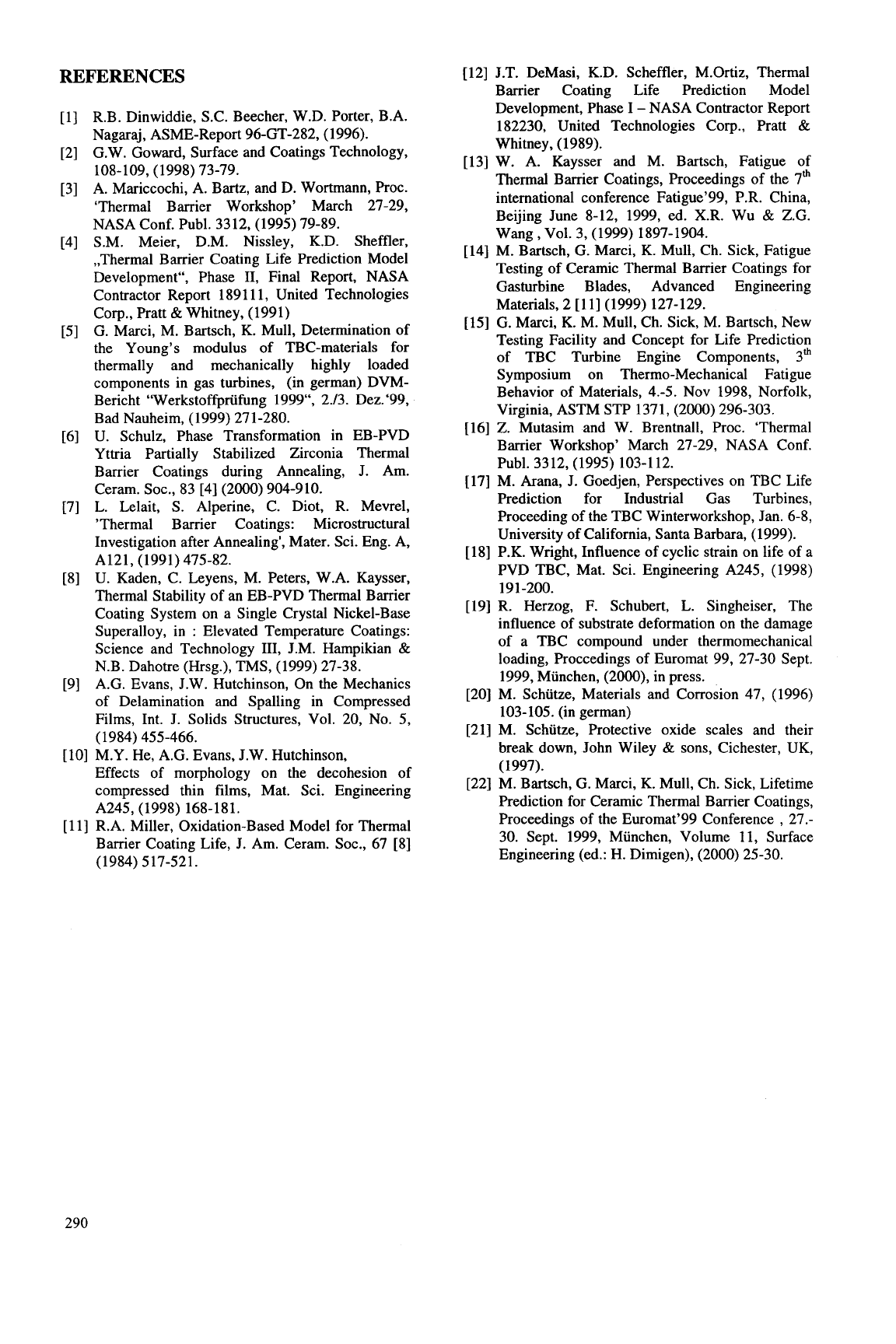
Fig.
5.
Schematic lifetime curves for a TBC-system for different
holding times (cycle time
2)
in TGMF-testing
I
' '
"""I
' '
"""I
'
'
"""I
' '
"""I
' '
'
I
'
' '
""'I
'
' '
""'I
' '
'
""'I
'
'
'
""'I
' '
"
I
10
100
1000
IOOW
100000
According to
our
experimental results no TBC
failure is expected for short-term loading, i.e. short
holding times at high temperature even at high
mechanical loading. In this load regime the lifetime of
the TBC will be limited by the lifetime of the substrate,
like it is sketched in Fig.
5.
Increased cycle time is
supposed to reduce the damage tolerance of the ceramic
top coat due to kinetic mechanisms like sintering. The
premature failure of the TBC will limit the lifetime of
the component in this case. During long term exposure
acceleration of TBC failure may occur by change of
dominating damage mechanisms by reason of different
time constants, e.g. oxidation
of
the bond coat after
sintering has been almost completed. Activating new
or
changing the dominating damage mechanisms will
consequently change the slope of the TBC lifetime
curve, as indicated in Fig.
5.
In
order to determine an interaction parameter
between fatigue and kinetic damage mechanisms and
verification of lifetime calculations we inte.nd to test
specimens with as coated TBC's in TGMF-cycles with
extended holding times.
Beside the cycle time and mechanical load level also
the cycle temperature level has to be varied to achieve
lifetime data for conditions at different blade locations.
That combinations
of
thermal and mechanical load
levels are relevant which entail premature failure of the
TBC at blade locations which lifetime after TBC failure
is less than the design life of the component
or
less than
the inspection intervals of the engine. How the relevant
load regime for TGMF-tests of TBC's can be delimited
by lifetime curves
of
the substrate without TBC has
been discussed in
[22].
However, we found that the load capability of a
specimen with TBC is increased compared to an
specimen without TBC even
if
the substrate temperature
during holding time is the same. This beneficial effect
of the TBC is due to a reduction of thermal shock.
CONCLUSIONS
Specimens with a ceramic thermal barrier coating
were tested
in
thermal gradient mechanical fatigue with
realistic alternating loads but extremely short holding
times. The results show that the as-coated properties of
EB-PVD TBC-systems are sufficient to survive the
required number of load alternations during service life.
Thus, the premature failure of TBC's observed in
service is due to time-at-high-temperature dependent
kinetic mechanisms. Fatigue damages due to cycling are
supposed to reduce TBC lifetime simultaneously to
damages by time-at-high-temperature dependent kinetic
processes. To determine the interaction effects between
fatigue and kinetic damage mechanisms TGMF-testing
of pre-aged specimen as well as TGMF-testing with
extended holding times are supposed to be suitable.
ACKNOWLEGEMENT
Portion of this work is financially supported by the
HGF strategy fund project 'Innovative Material Systems
for Increased Efficiency of Stationary Gas Turbines and
Aero Engines' of the 'Hermann von Helmholtz-
Gemeinschaft Deutscher Forschungszentren'
.
289
REFERENCES
[
121 J.T. DeMasi, K.D. Scheffler, M.Ortiz, Thermal
Barrier Coating Life Prediction Model
Development, Phase
I
-
NASA Contractor Report
182230, United Technologies Corp., Pratt
&
Whitney, (1989).
131 W. A. Kaysser and M. Bartsch, Fatigue of
Thermal Barrier Coatings, Proceedings of the 7*
international conference Fatigue’99, P.R. China,
Beijing June 8-12, 1999, ed. X.R. Wu
&
Z.G.
141 M. Bartsch, G. Marci,
K.
Mull, Ch. Sick, Fatigue
Testing of Ceramic Thermal Barrier Coatings for
Gasturbine Blades, Advanced Engineering
Materials, 2
[ll]
(1999) 127-129.
[15] G. Marci,
K.
M. Mull, Ch. Sick, M. Bartsch, New
Testing Facility and Concept for Life Prediction
of TBC Turbine Engine Components, 3”
Symposium on Thermo-Mechanical Fatigue
Behavior of Materials, 4.-5. Nov 1998, Norfolk,
Virginia, ASTM
STP
1371, (2000) 296-303.
[16]
Z.
Mutasim and W. Brentnall, Proc. ‘Thermal
Barrier Workshop’ March 27-29, NASA Conf.
[17] M. Arana, J. Goedjen, Perspectives on TBC Life
Prediction for Industrial Gas Turbines,
Proceeding of the TBC Winterworkshop, Jan. 6-8,
University of California, Santa Barbara, (1999).
[
181 P.K. Wright, Influence of cyclic strain on life of a
PVD
TBC,
Mat. Sci. Engineering A245, (1998)
[19] R. Herzog,
F.
Schubert, L. Singheiser, The
influence of substrate deformation on the damage
of a TBC compound under thermomechanical
loading, Proccedings of Euromat 99, 27-30 Sept.
1999, Miinchen, (2000), in press.
[20] M. Schutze, Materials and Corrosion 47, (1996)
103-105. (in german)
[21] M. Schiitze, Protective oxide scales and their
break down, John Wiley
&
sons, Cichester, UK,
(1997).
[22] M. Bartsch, G. Marci,
K.
Mull, Ch. Sick, Lifetime
Prediction for Ceramic Thermal Barrier Coatings,
Proceedings of the Euromat’99 Conference
,
27.-
30. Sept. 1999, Munchen, Volume 11, Surface
Engineering (ed.: H. Dimigen), (2000) 25-30.
Wag, Vol. 3, (1999) 1897-1904.
Publ. 3312, (1995) 103-112.
19 1-200.
R.B. Dinwiddie, S.C. Beecher, W.D. Porter, B.A.
Nagaraj, ASME-Report 96-GT-282, (1996).
G.W. Goward, Surface and Coatings Technology,
A. Mariccochi, A. Bartz, and D. Wortmann, Proc.
‘Thermal Barrier Workshop’ March 27-29,
NASA Conf. Publ. 3312, (1995) 79-89.
S.M. Meier, D.M. Nissley, K.D. Sheffler,
,,Thermal Barrier Coating Life Prediction Model
Development“, Phase
11,
Final Report, NASA
Contractor Report 1891 11, United Technologies
Corp., Pratt
&
Whitney, (1991)
G. Marci, M. Bartsch,
K.
Mull, Determination of
the Young’s modulus of TBC-materials for
thermally and mechanically highly loaded
components in gas turbines, (in german) DVM-
Bericht “Werkstoffpriifung 1999“, 2.13. Dez. ‘99,
Bad Nauheim, (1999) 271-280.
U. Schulz, Phase Transformation in EB-PVD
Yttria Partially Stabilized Zirconia Thermal
Barrier Coatings during Annealing, J. Am.
Ceram. SOC., 83 [4] (2000) 904-910.
L. Lelait,
S.
Alperine, C. Diot, R. Mevrel,
’Thermal Barrier Coatings: Microstructural
Investigation after Annealing‘, Mater. Sci. Eng. A,
U. Kaden, C. Leyens, M. Peters, W.A. Kaysser,
Thermal Stability of an EB-PVD Thermal Barrier
Coating System on a Single Crystal Nickel-Base
Superalloy, in
:
Elevated Temperature Coatings:
Science and Technology 111, J.M. Hampikian
&
N.B. Dahotre (Hrsg.), TMS, (1999) 27-38.
A.G. Evans, J.W. Hutchinson, On the Mechanics
of Delamination and Spalling in Compressed
Films, Int. J. Solids Structures, Vol. 20, No.
5,
108-109, (1998) 73-79.
A121, (1991) 475-82.
(1984) 455-466.
[lo] M.Y. He, A.G. Evans, J.W. Hutchinson,
Effects of morphology on the decohesion of
compressed thin films, Mat. Sci. Engineering
[
113 R.A. Miller, Oxidation-Based Model for Thermal
Barrier Coating Life,
J.
Am. Ceram. SOC., 67 [8]
A245, (1998) 168-181.
(1984) 517-521.
290
CREEP OF A SILICON NITRIDE UNDER VARIOUS SPECIMEN/LOADING
CONFIGURATIONS
Sung R. Choi, Lynn M. Powers, Frederic A. Holland, and John P. Gyekenyesi
NASA Glenn Research Center, Cleveland, Ohio
44135,
USA
ABSTRACT
Extensive creep testing of a hot-pressed silicon
nitride (NC132) was performed at 1300°C in air using
five different specimenlloading configurations,
including pure tension, pure compression, four-point
uniaxial flexure, ball-on-ring biaxial flexure, and ring-
on-ring biaxial flexure. Nominal creep strain and its
rate for a given nominal applied stress were greatest in
tension, least in compression, and intermediate in
uniaxial and biaxial flexure. Except for the case of
compressive loading, nominal creep strain generally
decreased with time, resulting in less-defmed steady-
state condition. Of the four different creep formulations
-
power-law, hyperbolic sine, step, and redistribution
models
-
the conventional power-law model provides
the most convenient and reasonable means to estimate
simple, quantitative creep parameters of the material.
Predictions of creep deformation for the case of
multiaxial stress state (biaxial flexure) were made based
on pure tension and compression creep data by using the
design code CARESICreep.
INTRODUCTION
Advanced ceramics are candidate materials for high-
temperature structural applications in gas turbine
engines and heat recovery systems. The
two
major
limitations
of
these materials, slow crack growth and
creep, are generally encountered in high-temperature
applications. At higher temperatures, particularly at
lower applied stress, enhanced creep takes place in the
form of permanent deformation and/or damage
accumulation, leading to loss of structural integrity and
possibly the eventual rupture of components.
Therefore, for higher-temperature applications, the
accurate determination of creep behavior including
creep and rupture parameters and associated
mechanisms is important for ensuring structural
integrity and component life.
Because of difference in
creep between tension and compression
[
1-31,
parameters that are derived from relatively easy flexural
testing using the conventional simple beam theory,
which assumes the neutral axis to be fixed, can be
misleading.
Many structural components are subjected
to multiaxial stresses, typically combined with tensile
and compressive stresses. Therefore, in order to
accurately predict or estimate creep deformation and
rupture of multiaxially stressed components, creep and
rupture parameters of a material should be determined
individually both in tension and in compression,
together with an appropriate predictionldesign
methodology.
The immediate objective of this work was to
develop and conduct creep testing to determine creep
behavior of a hot-pressed silicon nitride under various
loading configurations at 1300°C in air. The loading
configurations used in this study include pure tension,
pure compression, four-point uniaxial flexure, ball-on-
ring biaxial flexur
e, and ring-on-ring biaxial flexure. Creep displacements
for each specimenlloading configuration were
determined as a function of time with several different
levels of applied loads. NASA Glenn Research Center
has developed an analytical methodology and an
integrated design program named CARESICreep
(Ceramics Analysis and Reliability Evaluation of
Structureslcreep) to be used for predicting the creep
deformation and rupture life of structural ceramic
components
[4,5].
The second objective of this work
was to validate the CARESICreep design code on the
basis of the creep database generated from the
experimental work. This was done by predicting creep
deformation subjected to multiaxial (biaxial) stress state
based on the basis of pure tension and pure compression
data and by comparing with actual biaxial flexure data.
EXPERIMENTAL PROCEDURES
The material used in this work was a hot-pressed
silicon nitride (designated as NC132, Vintage 1990,
fabricated by Norton Co., Northboro,
MA)
containing
MgO as primary sintering aid. This material was
chosen since it has shown for decades a controlled
uniformity in mechanical and physical properties such
as hardness, fracture toughness, strength, and slow crack
growth, etc.
The material also has been extensively
characterized previously to determine fatigue andlor
creep life prediction parameters as a candidate gas
turbine material
[6-81.
Creep testing was performed in dead-weight creep
frames (Applied Testing Systems, Inc., Butler,
PA)
at
1300°C in air using five different specimenslloading
configurations, including pure tension, pure
compression, four-point uniaxial flexure, ball-on-ring
biaxial flexure, and ring-on-ring biaxial flexure. The
test specimenlloading configurations used in creep
testing are depicted in Figure
1.
Detailed experimental
procedures and techniques can be found elsewhere
[9].
Briefly, in pure tension, the dog-bone-shaped, pin-
loaded tension specimens with round cross-section
29
1