Heinrich J.G., Aldinger F. (Eds.) Ceramic Materials and Components for Engines
Подождите немного. Документ загружается.

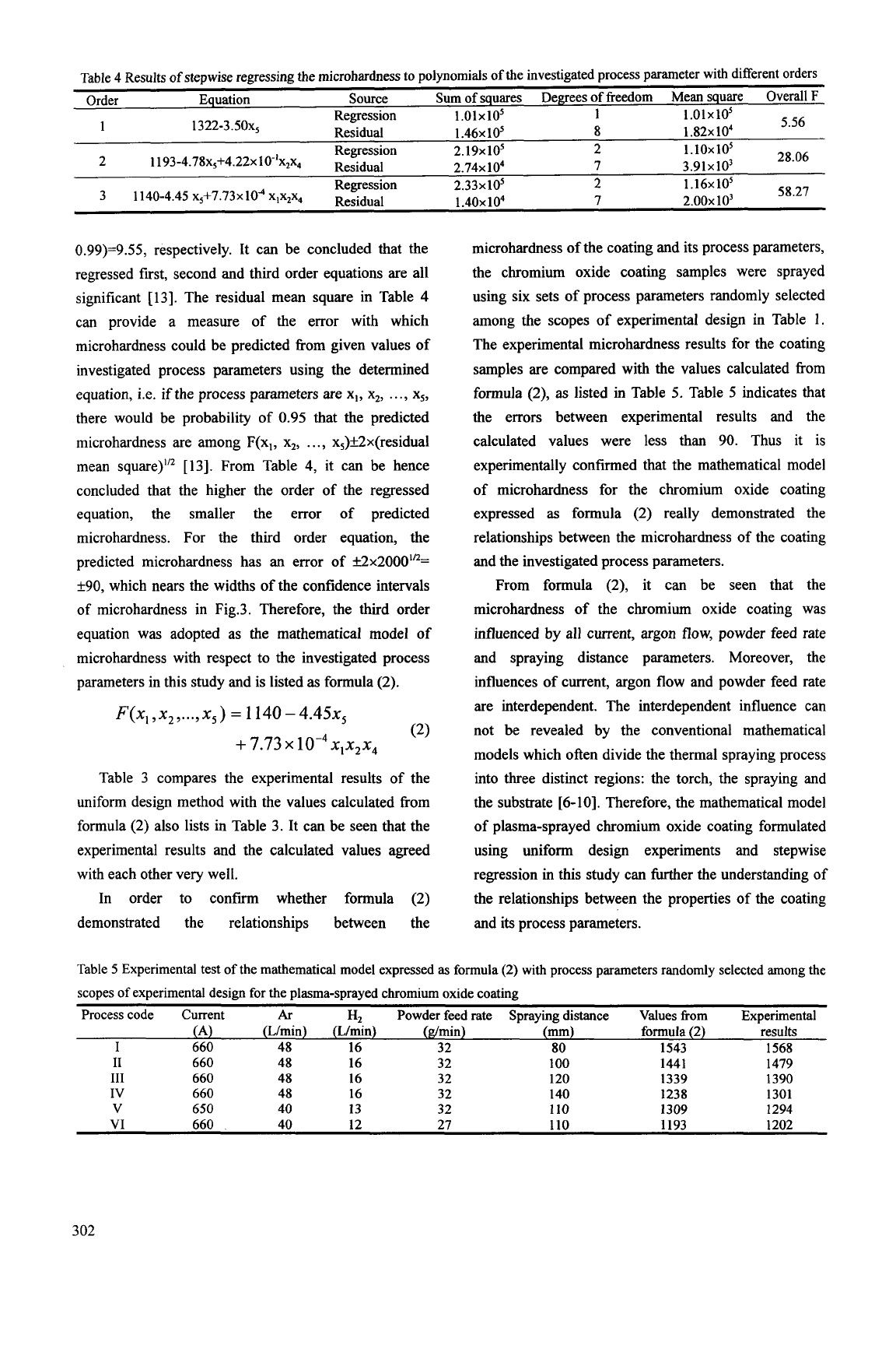
Table
4
Results
of
stepwise regressing the microhardness to polynomials of the investigated process parameter
with
different orders
Order
Equation Source
Sum
of
squares Degrees of freedom Mean square Overall
F
0.99)=9.55, respectively. It can be concluded that the
regressed first, second and third order equations are all
significant
[
131.
The residual mean square in Table
4
can provide a measure of the error with which
microhardness could be predicted fiom given values of
investigated process parameters using the determined
equation, i.e. if the process parameters are x,, x,,
.
.
.,
x5,
there would be probability of 0.95 that the predicted
microhardness are among F(x,, x,,
. . .
,
x5)k.2x(residual
mean square)”’ [13]. From Table
4,
it can be hence
concluded that the higher the order of the regressed
equation, the smaller the error of predicted
microhardness. For the third order equation, the
predicted microhardness has an error of &2x20001n=
k90,
which nears the widths of the confidence intervals
of microhardness in Fig.3. Therefore, the third order
equation was adopted as the mathematical model of
microhardness with respect to the investigated process
parameters in this study and is listed
as
formula
(2).
F(x,,
x2
)...)
X,
)
=
1 140
-
4.45~~
(2)
+
7.73
10-~
X,XzX4
Table
3
compares the experimental results of the
uniform design method with the values calculated
fiom
formula (2) also lists in Table
3.
It can be seen that the
experimental results and the calculated values agreed
with each other very well.
In order to confm whether formula (2)
demonstrated the relationships between the
microhardness of the coating and its process parameters,
the chromium oxide coating samples were sprayed
using six sets of process parameters randomly selected
among the scopes of experimental design in Table
1.
The experimental microhardness results for the coating
samples are compared with the values calculated fiom
formula
(2),
as
listed in Table
5.
Table
5
indicates that
the errors between experimental results and the
calculated values were less than 90. Thus it is
experimentally confmed that the mathematical model
of microhardness for the chromium oxide coating
expressed
as
formula (2) really demonstrated the
relationships between the microhardness of the coating
and the investigated process parameters.
From formula (2), it can be seen that the
microhardness of the chromium oxide coating was
influenced by all current, argon flow, powder feed rate
and spraying distance parameters. Moreover, the
influences of current, argon flow and powder feed rate
are interdependent. The interdependent influence can
not be revealed by the conventional mathematical
models which often divide the thermal spraying process
into three distinct regions: the torch, the spraying and
the substrate
[6-lo].
Therefore, the mathematical model
of plasma-sprayed chromium oxide coating formulated
using uniform design experiments and stepwise
regression in this study can further the understanding of
the relationships between the properties of the coating
and its process parameters.
Table
5
Experimental test
of
the mathematical model expressed
as
formula
(2)
with
process parameters randomly selected among the
scopes of experimental design for
the
plasma-sprayed chromium oxide coating
Process code Current
Ar
H,
Powder feed rate SDraving distance Values from ExDerimental
.*v
(A)
(L/min)
(L/iin)
(ghin)
(mm)
formula
(2)
results
I
660 48
16
32 80
1543
1568
I1
660 48
16
32 100
1441
1479
I11
660 48
16 32
120 1339 1390
IV
660 48
16 32
140 1238 1301
V
650
40
13
32
110 1309 1294
VI
660 40
12 27
110 1193
1202
3
02
CONCLUSION
The mathematical model of microhardness for
plasma-sprayed Cr,O, coating with respect to the
process parameters including plasma gas flow,
current, spraying distance and powder feed rate was
formulated using experimental method of uniform
design and stepwise regression. The mathematical
model was expressed
as
a third order polynomial
of
the parameters. It was experimentally confirmed that
the mathematical model demonstrated the
relationship between the microhardness of the
coating and its process parameters. The mathematical
model revealed that interdependent influences on the
microhardness existed between the process
parameters, and it can further the understanding of
the relationship between the properties
of
the coating
and its process parameters.
REFERENCES
(1)
R. W. Smith and R. Novak, Advances and
Application in
U.
S.
Thermal Spray Technology,
I.
Technology and Materials. Powder Metallurgy
International
3, (1991) 147-155.
(2)
G.
Barbezat, A. R. Nicoll and A. Sickinger,
Abrasion, Erosion and Scuffing Resistance of
Carbide and Oxide Ceramic Thermal Sprayed
Coating for Different Application. Wear,
162-164,
(1 993) 529-537.
(3)
J.
E.
Fernandz, Yinglong Wang and
R.
Tucho et al,
Friction and Wear Behaviour
of
Plasma-Sprayed
Cr,O, Coatings Against Steel in a Wide Range of
Sliding Velocities and Normal Loads. Tribology
International,
29(4), (1996) 333-343.
(4)
G.
Barbezat, A. R. Nicoll and
Y.
S.
Yin et al,
Abrasive Wear Performance of Cr3C,-25%NiCr
Coatings by Plasma Spray and CDS Detonation
Spray. Tribology Transactions,
38, (1995) 845-850.
(5)
E.
Lugscheider,
I.
Rass and
H.
L.
Heijnen et al,
Comparison
of
the Coatings Properties of Different
Types of Powder Morphologies. Thermal Spray:
International Advances in Coatings Technology, C.
C. Berndt, Rd., ASM International,
(1992) 967-973.
(6)
D. R. Mash, N.
E.
Weare and D.
L.
Walker, Process
Variables in Plasma-Jet Spraying. Journal of Metal,
13(7), (1961) 473-478.
(7)
M. Vardelle, A. Vardelle and P. Fauchais, Spray
Parameter and Particle Behaviour Relationships
During Plasma Spraying. Journal
of
Thermal Spray
Technology,
2(
I),
(1 993) 79-9
1.
(8)
H. Fukanuma, A Porosity Formation and Flattening
Model of an Imping Molten Particle in Thermal
Spray Coatings. Journal
of
Thermal Spray
Technology,
3( l), (1 994) 33-44.
(9)
S.
Das, V.
K.
Suri and
U.
Chandra et al, One-
Dimensional Mathematical Model for Selecting
Plasma Spray Process Parameters. Journal
of
Thermal Spray Technology,
4(2),
(1
995)
153-
162.
(1
0)K.
T. Fang, Uniform Design and Tables of Uniform
Design, Science Press, Beijing,
(1 994).
(1
1)K.
T. Fang, Y. Wang, Number-Theoretic Methods
in Statistics, Chapman and Hall, London,
(1993).
(12)C.
K.
Lin, C. C. Berndt, Statistical Analysis of
Microhardness Variations
in
Thermal Spray
Coatings.
Journal
of Materials Science,
30, (1995)
(13)N.
R.
Draper,
H.
Smith, Applied Regression
Analysis, John Wiley
&
Sons, New York
0
Chichester Brisbane
0
Toronto Singapore,
(1981)
11
1-1 17.
303

This Page Intentionally Left Blank
LIFE TIME PREDICTION MODEL FOR PLASMA-SPRAYED THERMAL
BARRIER COATINGS BASED ON A MICROMECHANICAL APPROACH
R
VaSen, G. Kerkhoff,
M.
Ahrens,
D.
Stover
Forschungszentrum Julich GmbH,
Institut fur Werkstoffe und Verfahren der Energietechnik
1,
D-52425
Jiilich, Germany
ABSTRACT
A typical thermal barrier coating (TBC) system
consists of a dense bondcoat layer (e.g. an oxidation
resistant NiCoCrAIY-alloy) and a porous zirconia
stabilized with 7
-
8
wt.
%
ma. A frequently used
method to produce these coatings is the plasma
spraying process. In order to obtain sufficient
adherence of the ceramic top coat to the bondcoat a
certain bondcoat roughness (Ra 5-8 pm) is necessary.
It is now found that during thermal cycling operation
these systems often fail within the top coat by crack
initiation and propagation close to the bondcoat
-
top
coat interface. This type of failure mechanism can be
explained by stresses arising from the formation of a
thermally grown oxide (TGO) layer on the rough
bondcoat surface. TGO formation, creep effects in both
bondcoat and top coat and roughness
of
the bondcoat
lead to a rather complex stress state. All these factors
have been taken into account by using a finite element
method (FEM) to calculate stress development during
thermal loading. These data were then introduced into
a crack propagation model to estimate crack
development during thermal cycling operation.
INTRODUCTION
Thermal barrier coating (Tl3Cs) systems are often
applied
to
metallic components in gas turbines to
improve the performance of the engines. Without a
change of the turbine inlet temperature (TIT) the use of
TBCs leads to a reduction
of
the metal temperature and
hence to an increase of the components life time.
Alternatively, a TBC system enables an increase of the
TIT and, as a result, a higher efficiency of the engine
TBC systems consist in most cases of a bondcoat
and a 7-8
wt.
%
yttria stabilized zirconia topcoat. The
bondcoat protects the substrate from oxidation and
enables the bonding of the topcoat. Two different
techniques to produce the top coat are widely used.
One process is the electron beam physical vapor
deposition (EB-PVD). For these EB-PVD topcoats Pt-
aluminide or also peened MCrAlY-bondcoats (M=Co,
Ni) with a rather smooth surface are often used. The
second process is the atmospheric plasma spraying
(APS). In most cases the APS-TBC is deposited on
MCrAlY bondcoats with a rather rough surface
(5-7
pm) produced by vacuum plasma spraying
(VPS).
More details are found in several review articles
[2,
3,
4, 5,671.
PI.
The use of TBC systems in industrial applications is
connected with the availability of a reliable life
prediction model which is essential for the design of
turbine engines. At present, life time models are mainly
based on empirical approaches
[8,
9, 10 ,11 ,121 which
need the knowledge of the rather complex and partially
difficult to determine thermo-mechanical data of the
specific TBC system. In the present investigation a life
time model for plasma-sprayed TBC systems which is
based on their microstructure is presented. We assume
that this model can lead to more reliable predictions
and to a better understanding
of
the system. The
improved understanding should lead to the
identification
of
the key factors controlling the life of
the TBC system. Detailed strategies for an optimization
of the system are expected.
In order to develop a microstructural based life time
model the stress state in the plasma-sprayed TBC
system is evaluated. As it is generally accepted that the
formation of the thermally grown oxide (TGO) during
high temperature exposure is a significant factor which
determines life time of the system it
is
included in the
model. Furthermore, the roughness of the bondcoat as
well as the curvature of the substrate are considered.
The results of the stress evaluation are then used to
develop a model which describes the growth of the
microcracks in the TBC. The assumptions made in the
model and the predictions are compared with
experimental results from thermal cycling tests.
EXPERIMENTAL
Thermal cycling tests have been performed with
disk-shaped specimens with 30
mm
diameter and 3
mm
hckness. The outer edge was beveled to reduce
stresses at the outer free edge of the sample [13]. One
side of the samples was coated with a 150 pm thick
NiCoCrAlY bondcoat by VPS using an F4 gun in a
Sulzer Metco plasma spray unit. A typical roughness
value of
6.4
pm was found for most of the produced
coatings. Some of the samples have been pre-oxidized
before cycling at
1000
"C for 100 h in air. In this case
the bondcoat roughness varied between about 4.9 and
7.2
pm.
The
8
wt.
%
YSZ topcoat was applied by an APS
process with a Triplex gun in a Sulzer Metco APS
facility. The thickness of the coatings were about 300
pm, the porosity was between 12 and 13
%.
Thermal
cycling was performed in a gas burner test facility
which operated with natural gas and oxygen. The
specimens were heated from the TBC side while
305
cooled with compressed air from the back. After the
heating period of
5
min the burner was moved away
from the surface and the sample was also cooled from
the front with compressed air for
2
min.
In addition to
this standard cycle a shorter cycle with about half the
heating and cooling time was used for specimens pre-
oxidized prior to cycling. The surface temperature was
measured with a pyrometer operating at wavelengths
between
8
and 13 pm. In the middle of the substrate a
1
mm
hole was drilled to the center of the substrate. In
this hole a thermocouple was fixed to measure the
substrate temperature. In the experiments it took about
20
s
to reach the maximum surface temperature. The
steady state surface temperature during the heating
phase was about 1250 "C, the temperature measured at
the thermocouple was about 970°C which
corresponded to about 1000 "C at the interface.
The lengths
of
50
cracks in the TBC were measured at
three different locations. The exact position of the
areas, which had a width of
50
pm, are shown in Fig.
1. The position of the investigated areas were in the
middle of the TBC 70 pm away from the interface (1
in Fig. 1) and close to the interface
(2).
Additionally,
crack sizes at the beveled edge were measured (3).
From the area which had to be evaluated to measure
50
cracks the crack density was calculated.
I
i
3
i
As we did not observe segmentation cracks in the
coatings after thermal cycling, relaxation by sliding
along the interfaces of the spray lamellae, where a lot
of microcracks are located, might occur. As no reliable
data of this high temperature relaxation are available
we assume that the relatively high stress levels are
build up in the coating and are relaxed by creep
mechanisms. These calculations performed with
literature data for the creep behavior of TBCs give a
fast relaxation of the high temperature stress state.
These relaxation leads to a compressive in-plane stress
in the coating after cooling down to room temperature.
In fact, we measured with X-Ray diffraction
techniques, that the surface stress in the TBC of
a
cylindrical specimen was reduced from about
5
MPa to
about -20MPa after one cycle at
1000
"C for
2
h.
These results made it reasonable to assume that the
high-temperature stress level is very low after a limited
number of thermal cycles. For a simplification of the
discussion we will assume a stress-free TBC at high
temperatures. At a later state of the model
development, when precise relaxation data of TBC and
bondcoat are available, these effects can be included.
They will lead to lower stress levels in the TBC at
room temperature.
The first parameter which we will discuss is the
curvature of the substrate. A cylindrical geometry was
used as shown in Fig.
2.
bondcoat (NiCoCrAlw
I
i
i
substrate
(IN734
Fig. 1 Schematic drawing of a part of the thermal
cycling test specimens. The three locations, where the
crack lengths were measured, are indicated
(
1-3)
MODEL DESCRIPTION
For the development
of
our model it is essential to
know details about the stress states within a plasma-
sprayed TBC. The calculations have been performed
with the finite element code ABAQUS using materials
data which are published elsewhere [14]. Of special
importance for the understanding of the stress
development in a TBC system are the thermal
expansion coefficients. These are high for the substrate
and the bondcoat
(>
15.10-6
K),
intermediate for the
YSZ
topcoat (10
-
1 1.10-6
K)
and rather low for the
thermally grown oxide made of alumina (8-10'6
K).
From literature data and also from our own
XRD
stress measurements it is known that the stress state in
as-sprayed TBCs is rather low, typically
of
the order of
10
MPa or less
[15].
If such a system is heated to
elevated temperatures, a tensile stress state will be
found in the TBC. For
AT
of 1000
K
an estimation will
give an approximate value
of
200
MPa in-plane
stresses. Probably the ceramic can not withstand such
high tensile stress without some kind of relaxation.
bondcoat
thickness
150
pm
Fig.
2
Cylindrical geometry used in the finite element
calculations.
Cooling down such a cylindrical system from the
stress-free high temperature state will result in in-plane
compressive stresses
and,
more important, radial
tensile stresses
in
the TBC. The origin of these radial
stresses is
the larger thermal expansion coefficient of
the substrate compared to the TBC, as it is also the case
for the in-plane stress. The inner metallic cylinder will
contract more during cooling than the outer cylinder
and hence, a radial saess will develop at the interface.
As shown in Fig. 3 the stress level depends on the
radius of the substrate, which
is
inversely proportional
to the curvature. The higher the curvature the higher
the stress level. It is also interesting to note that a
thicker TBC will increase the stress level nearly
306
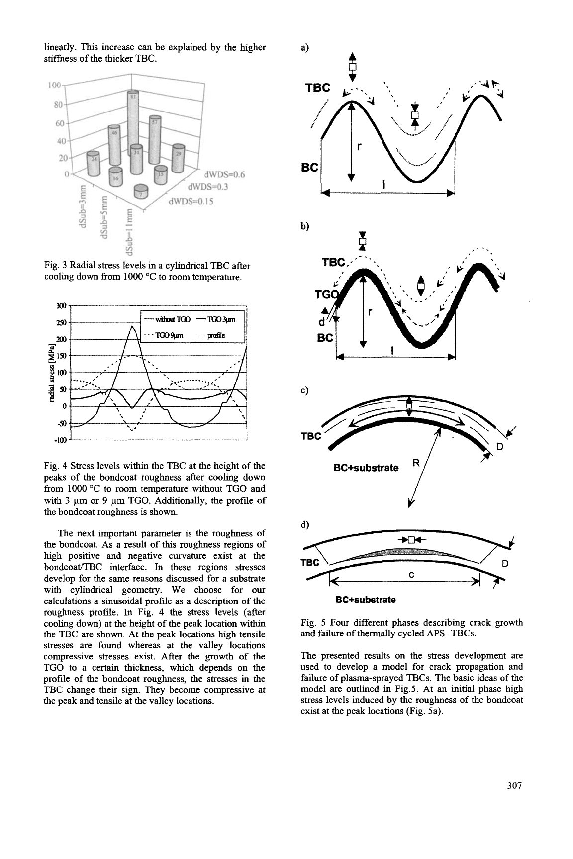
linearly. This increase can be explained by the higher
stiffness of the thicker TBC.
a
Fig.
3
Radial stress levels in a cylindncal TBC after
cooling down from 1000 "C to room temperature.
-100
1-
-.J
Fig.
4
Stress levels within the TBC at the height of the
peaks of the bondcoat roughness after cooling down
from
1000
"C to room temperature without TGO and
with
3
pm or
9
pm TGO. Additionally, the profile of
the bondcoat roughness is
shown.
The next important parameter is the roughness of
the bondcoat. As a result of this roughness regions of
high positive and negative curvature exist at the
bondcoat/TBC interface. In these regions stresses
develop for the same reasons discussed for a substrate
with cylindncal geometry. We choose for our
calculations a sinusoidal profile as a description of the
roughness profile.
In
Fig.
4
the stress levels (after
cooling down) at the height of the peak location within
the TBC are
shown.
At the peak locations high tensile
stresses are found whereas at the valley locations
compressive stresses exist. After the growth of the
TGO to a certain thickness, which depends on the
profile of the bondcoat roughness, the stresses in the
TBC change their sign. They become compressive at
the peak and tensile at the valley locations.
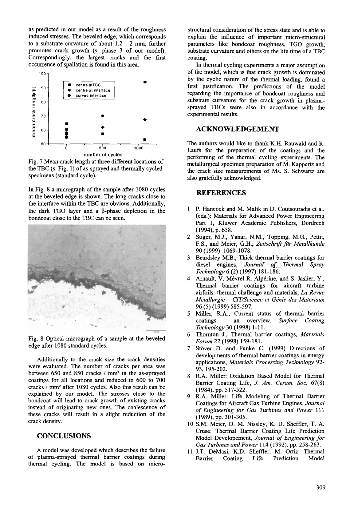
k
I
BC+su
bstrate
II-
f'
BC+su
bstrate
Fig.
5
Four different phases describing crack growth
and failure of thermally cycled
APS
-TBCs.
The presented results on the stress development are
used to develop a model for crack propagation and
failure of plasma-sprayed TBCs. The basic ideas of the
model are outlined in Fig.5. At an initial phase high
stress levels induced
by
the roughness of the bondcoat
exist at the peak locations (Fig. 5a).
307
They lead to a crack extension of the existing
microcracks between the spray lamellae. As the
interfaces between the spray lamellae close to the
BC/TBC interface are similar shaped as this interface,
the cracks will run into the valley locations. Due to the
compressive stress level they will be arrested there. We
propose that crack
propagation is mainly controlled by the cyclic nature of
the loading. In this case the crack growth per cycle
dc/dN can often be described by the following
empirical law:
(1)
dN
AKI
is the difference in stress intensity factors
during the cycle,
KI,~
is the critical stress intensity
factor, and A, n are constants.
This situation will change in the second phase when
considerable TGO growth takes place (Fig. 5b). As
stated above, the stress at the valley locations will be
converted to tensile and cracks can grow further. Long
cracks can be formed during
this
state by coalescence
of cracks running from different peak locations into the
same valley.
Once these long cracks have been formed, the
curvature of the substrate has to be considered (Fig.
5c). Stress levels due to typical curvatures existing in
turbine blades
(<
0.5
/mm)
are below
30
MPa
(s.
Fig.
3).
For the largest initial crack lengths of about 100 pm
(s.
below) the stress intensity factor can be estimated to
be below
0.4
by using the simple equation
derived for a crack
of
length c in an infinite plane [16]:
AK,
=
c+g
As this value is considerably lower than the critical
stress intensity factor in TBCs (about 1
-
2
MPamO.’
[17, 18]), we expect only a minor contribution of the
substrate curvature induced stresses to crack growth
during the initial phase. However, due to crack growth
during phase 1 and
2
large cracks with crack size of
200 pm and longer are formed. The stress intensity
factor will increase considerable
(>
40
%),
fast crack
growth might be observed for the longest cracks.
In the final phase (phase
3)
the crack will reach a
length at which spallation of the coating will occur
(Fig. 5d). This crack length c can be estimated using
elasticity theory
[19].
For a coating with thickness
D,
Young’s modulus
E,
Poisson ratio
v
under tangential
compressive stress
(T
the critical crack length c is:
I/Z
c=
2.21
D(
ETBc
)
(1-2)ff
(3)
RESULTS
AND DISCUSSION
The cycling of the pre-oxidized specimens was
stopped after
400
cycles. All investigated specimens
showed spallation of the TBC in the area of the beveled
edge. A variation in the amount of spallation existed
between different specimens, however no systematic
difference between samples cycled with short and
standard cycles could be found. These results
correspond with the results of crack size
measurements. Samples with short and long cycles
have similar crack lengths after
400
cycles (Fig. 6).
These results confii the assumption that crack growth
is determined by the cyclic nature of the thermal
loading as proposed by equation (1).
shortcycle
long cycle
E
v
IOOh,
1000°C
E
75
€
T
451
center in
TBC
center at interface curvature
at
interface
Fig.
6
Crack length of as-sprayed, pre-oxidized and
cycled
(400
cycles) specimens at the different
locations.
---I+as-sprayed\
14
--
1
12
$10
$*
w-
0
$6
E
z4
2
0
0
50
100
150
crack
size
[pm]
Fig. 6 Crack size distribution of as-sprayed and
thermally cycled specimens at the beveled edge
location (standard cycle).
Samples in the as-sprayed condition and after
500
and 1080 cycles without pre-oxidation have
additionally been evaluated. Only the sample cycled
for 1080 cycles showed spallations in the region of the
beveled edge. The crack size distributions of samples
after
0,
500,
and 1080 cycles measured at the beveled
edge are shown in Fig. 6. The crack size distributions
are rather broad with a number of large cracks up to
100
pm
also in the as-sprayed coating. During cycling
the distribution shifts to larger crack lengths. An
increasing amount of cracks above 100 pm is found.
This tendency is also obvious in Fig. 7, in which the
mean crack lengths at the three different locations are
shown. Only the cracks in the center within the TBC
show a decrease of crack size with increasing cycle
numbers. This might be a result of the sintering of the
cracks. Close to the bondcoat interface the cracks grow
308
as predicted in our model as a result of the roughness
induced stresses. The beveled edge, which corresponds
to a substrate curvature of about 1.2
-
2
mm,
further
promotes crack growth
(s.
phase
3
of our model).
Correspondingly, the largest cracks and the first
occurrence of spallation is found in this area.
loo
1
+
centre at interface
B
curved interface
i
s
E
6oj
I
50
!
0
500
1000
number
of
cycles
Fig. 7 Mean crack length at three different locations of
the TBC
(s.
Fig. 1) of as-sprayed and thermally cycled
specimens (standard cycle).
In Fig. 8 a micrograph of the sample after 1080 cycles
at the beveled edge is shown. The long cracks close to
the interface within the TBC are obvious. Additionally,
the dark TGO layer and a P-phase depletion in the
bondcoat close to the TBC can be seen.
-1
*
'
*-
Fig. 8 Optical micrograph of a sample at the beveled
edge after 1080 standard cycles.
Additionally to the crack size the crack densities
were evaluated. The number of cracks per area was
between 650 and 850 cracks
I
mm2
in the as-sprayed
coatings for all locations and reduced to 600 to 700
cracks
/ mm2
after 1080 cycles. Also this result can be
explained by our model. The stresses close
to
the
bondcoat will lead to crack growth of existing cracks
instead of originating new ones. The coalescence of
these cracks will result in a slight reduction
of
the
crack density.
CONCLUSIONS
A model was developed which describes the failure
of plasma-sprayed thermal barrier coatings during
thermal cycling. The model is based on micro-
structural consideration of the stress state and is able to
explain the influence of important micro-structural
parameters ldce bondcoat roughness, TGO growth,
substrate curvature and others on the life time of a TBC
coating.
In thermal cycling experiments a major assumption
of the model, which is that crack growth
is
dominated
by the cyclic nature of the thermal loading, found a
first justification. The predictions of the model
regarding the importance of bondcoat roughness and
substrate curvature for the crack growth in plasma-
sprayed TBCs were also in accordance with the
experimental results.
ACKNOWLEDGEMENT
The authors would lke to thank K.H. Rauwald and R.
Laufs for the preparation of the coatings and the
performing of the thermal cycling experiments. The
metallurgical specimen preparation of M. Kappertz and
the crack sue measurements of Ms.
S.
Schwartz are
also gratefully acknowledged.
REFERENCES
P. Hancock and M. Malik in D. Coutsouradis et al.
(eds.): Materials for Advanced Power Engineering
Part 1, Kluwer Academic Publishers, Dordrech
(1994), p. 658.
Stiger, M.J., Yanar, N.M., Topping, M.G., Pettit,
F.S.,
and Meier, G.H.,
Zeitschrift fur Metallkunde
Beardsley M.B., Thick thermal barrier coatings for
diesel engines,
Journal
e$-
Thermal Spray
Technology
6
(2)
(1997) 181-186.-
Amault,
V,
MCvrel R. Alptrine, and
S.
Jaslier, Y.,
Thermal barrier coatings for aircraft turbine
airfoils: thermal challenge and materials,
La Revue
Mktallurgie
-
CIT/Science et GCnie des Matkriaux
Miller, R.A., Current status of thermal barrier
coatings
-
an overview,
Surface Coating
Technology30
(1998) 1-11.
Thomton J., Thermal barrier coatings,
Materials
Forum
22 (1998) 159-181.
Stover D. and Funke C. (1999) Directions of
developments of thermal barrier coatings in energy
applications,
Materials Processing Technology
92-
R.A. Miller: Oxidation Based Model for Thermal
Barrier Coating Life,
J.
Am. Ceram.
SOC.
67(8)
R.A. Miller: Life Modeling of Thermal Barrier
Coatings for Aircraft Gas Turbine Engines,
Journal
of
Engineering
for
Gas
Turbines and Power
111
90 (1999) 1069-1078.
96
(5)
(1999) 585-597.
93,
195-202.
(1984), pp. 517-522.
(1989),
pp.
301-305.
10
S.M. Meier, D. M. Nissley, K. D. Sheffler, T. A.
Cruse: Thermal Barrier Coating Life Prediction
Model Developement,
Journal
of
Engineering for
Gas
Turbines and Power
114 (1992), pp. 258-263.
11 J.T. DeMasi, K.D. Sheffler, M.
Ortiz:
Thermal
Barrier Coating Life Prediction Model
309
Developement, Phase
I
Final Report, Contract
NAS3-23944, NASA CR 182230 (1989).
12 S.M. Meier, D.M. Nissley, K.D. Sheffler: Thermal
Barrier Coating Life Prediction Model
Development, Phase
11
Final Report, Contract
NAS3-23944, NASA CR 1891 11, (1991).
13 C. Funke, J.C. Mailand, B. Siebert, R. VaBen, D.
Stover: "Characterisation of
ZrO2
-
7
wt??
Y2O3
Thermal Barrier Coatings with Different Porosities
and FEM Analysis of Stress Redistribution During
Thermal Cycling of TBC's"
Suflace Coatings and
Technologies,
94-95 (1997) 106-1 11.
14
G. Kerkoff, R. VaSen, D. Stover, Numerically
calculated oxidation induced stresses in thermal
barrier coatings on cylindrical substrates,
European
Federation
of
Corrosion Publications
27 (1999)
15
G. Kerkhoff, Thesis, Ruhr Universitiit Bochum,
Germany,
(2000).
16
H.L.
Ewalds, R.J.H. Wanhill, in Fracture
Mechanics, Edward Arnold Publishers, London
(1986) p. 32.
17
G.K. Beshish, C.W. Florey,F.J. Worzala, W.J.
Lenling
,
Fracture Toughness of Thermal Spray
Ceramic Coatings Determined by the Indentation
Technique,
Journal
of
Thermal Spray Technology
18
R. Vassen,
X.
Cao, F. Tietz, D. Basu, D. Stover,
Zirconates as
New
Materials for Thermal Barrier
Coatings,
to be published in
J.
Am. Ceram.
19
S.
Timoshenko, J.M. Gere, Theory of Elastic
Stability, Engineering Society Monographs, New
York (1936).
373-382.
2, 1 (1993) 35-38.
s0c.(2000).
310
ANALYTICAL DESIGN AND EXPERIMENTAL VERIFICATION
METHODS
OF
CERAMIC RADIAL, TURBINE ROTORS
FOR
A
GAS
TURBINE
Norio Nakazawa
Tsukuba College of Technology, Tsukuba-Shi, Japan
ABSTRACT
Radial turbine rotors were designed and evaluated
for a prototype automotive gas turbine using several test
rigs with a turbine inlet gas temperature of 1350°C.
One of the most important goals of the gas turbine
engine development was to demonstrate
40%
thermal
efficiency without dependence on any cooling systems
for the turbine components. This program was
conducted by the Petroleum Energy Center in
japan.'')^'^)
The materials of the rotors were Si,N4, and test
pieces including those cut from actual rotors were
evaluated through flexural and tensile tests for fast
fracture and long-term life.
Several types of rotors were designed and
manufactured with the goal of improving strength
reliability and aerodynamic performance. FEM models
were produced to calculate temperature and elastic
stress distributions, and the design procedures with
probability calculations were then applied to analyze
reliability and life span using the material properties.
Many rotors were evaluated through cold and hot
spin tests which included burst tests and these results
were correlated with the theoretical analyses in order to
verify the effectiveness of the manufacturing processes
and the design, and also to provide feed back for the
next step in design evolution. Some types of rotors were
proven by hot spin and endurance tests and then
assembled into the engines.
Failures due to blade resonance vibrations were
observed and analyzed in combination with the
experiments to modify the blade design. Foreign object
impact damage was also encountered in the engine tests
and turbine test rigs. Trap systems were designed to be
placed upstream of the turbine. These were installed in
the engines and the test rigs and demonstrated their
effectiveness.
This work is partially supported by the Agency of
Industrial Science and Technology (AIST) in the
Ministry
of
Trade and Industry (MITI).
DESIGN AND
EVALUATION METHOD
Long-term life
A design goal of continuous running hours was
established for the turbine under steady state operation
at the rated engine conditions. Limits in rotor life due to
cracks originating from small defects (static fatigue)
which were assumed to be included in the materials
during the manufacturing processes, as well as limits
due to creep phenomena, were considered in the design.
In
designing for static fatigue life, reliability
analyses using statistical calculations in regard to
material properties, such as the Weibull modulus and
static fatigue exponents, were combined with elastic
stress analysis. Defect sizes and their distributions in
the actual components depend
on
their dimensions and
shapes, and then
on
the manufacturing process,
Therefore the strength and life of the components vary
as a result of them. These variations were measured and
reflected in the design.
Creep phenomena of the silicon nitrides adopted for
the components seem much different from those of
super alloys. What occurs in the materials'
microstructure is that the sintering additives in the grain
boundaries move to the material surfaces and are
oxidized. Pores in the boundary due to these additives'
movements are newly generated defects that influence
the strength of the material. These phenomena are not
yet fully understood and it is difficult to determine an
appropriate design method in the light of them.
Therefore we avoided designing components which
include these creep conditions.
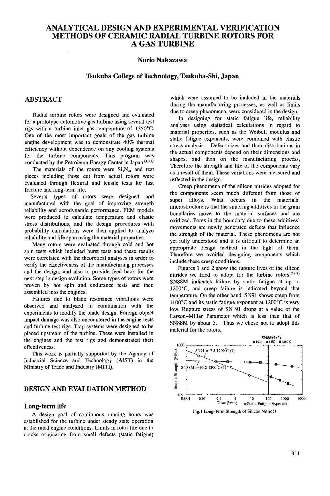
Figures
1
and 2 show the rupture lives of the silicon
nitrides we tried to adopt for the turbine rotors.('),(*)
SN88M indicates failure by static fatigue at up to
1200"C, and creep failure is indicated beyond that
temperature.
On
the other hand, SN91 shows creep from
1100°C and its static fatigue exponent at 1200°C is very
low. Rupture stress of
SN
91 drops at a value of the
Larson-Millar Parameter which is less than that of
SN88M by about
5.
Thus we chose not
to
adopt this
material for the rotors.
SN88M
(2)
81038
01150
m1350'C
0.001
001
01
1
10
100
iooo
ionno
Time
(hour)
n:Static
Fatigue
Exponent
Fig.1
Long-Term
Strength
of
Silicon
Nitrides
311