Hussian Z., AbdullahM.Z., AlimuddinZ. Basic Fluid Mechanics and Hydraulic Machines
Подождите немного. Документ загружается.

160 Basic Fluids Mechanics and Hydraulic Machines
7.3
Analysis and Construction
of
Velocity Diagram
The runner blades are long and there
is
large difference
in
radii between the hub and tip
of
the blades. Therefore velocity diagrams are drawn at the mean radius
of
the blade. The
axial flow velocity
is
constant as inlet and exit and hence
VIf=
V
2f
=
VI'
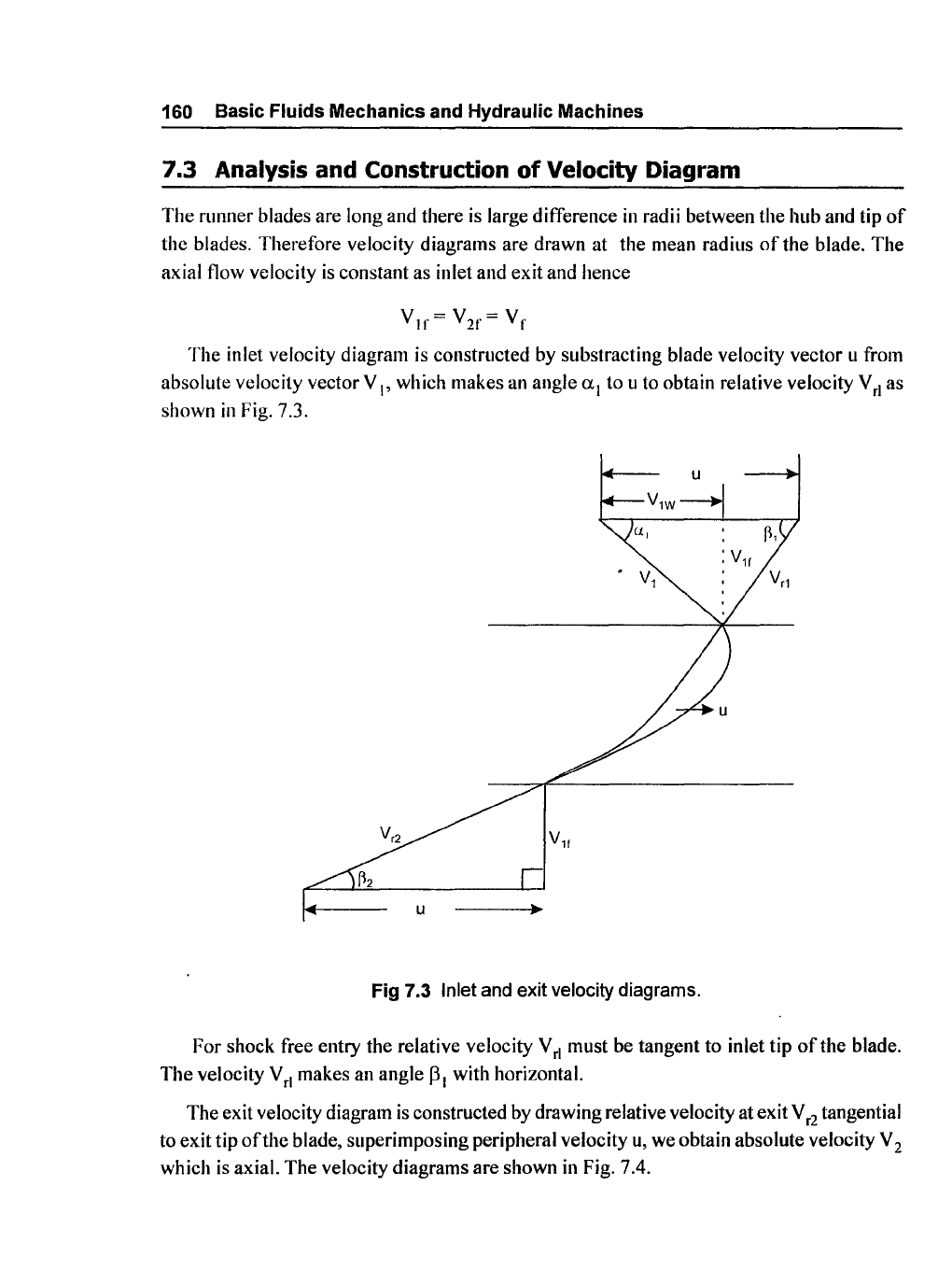
The inlet velocity diagram
is
constructed
by
substracting blade velocity vector u from
absolute velocity vector V
I'
which makes an angle a
l
to u to obtain relative velocity V
rl
as
shown
in
Fig. 7.3.
u
V1w4
u
Fig 7.3 Inlet and exit velocity diagrams.
For shock free entry the relative velocity V
rl
must be tangent to inlet tip
of
the blade.
The velocity V
rl
makes an angle
PI
with horizontal.
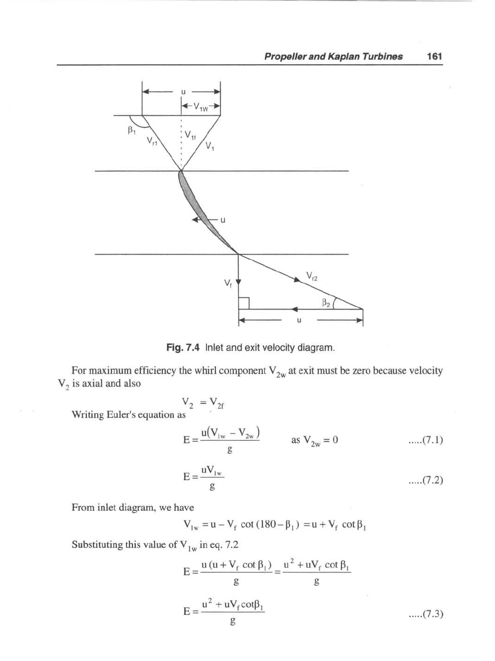
The exit velocity diagram
is
constructed by drawing relative velocity at exit V
r2
tangential
to exit tip
ofthe
blade, superimposing peripheral velocity
u,
we obtain absolute velocity V 2
which
is
axial. The velocity diagrams are shown
in
Fig. 7.4.
Propeller and Kaplan Turbines
161
Fig. 7.4 Inlet and exit velocity diagram.
For maximum efficiency the whirl component V 2w at exit must be zero because velocity
V 2 is axial and also
V
2
= V
2f
Writing Euler's equation as
E=
U(V1W
- V
2W
)
g
uV
1w
E=--
g
From inlet diagram, we have
as V
2w
= 0
V
1w
=u-V
f
cot(180-~I)
=u+V
r
cot~l
Substituting this value
of
V
Iw
in eq. 7.2
E = u (u +
V r cot
~
I) = u 2 + u V r cot
~
I
g g
..... (7.1)
..... (7.2)
..... (7.3)
162 Basic Fluids Mechanics and Hydraulic Machines
If
E
is
constant along the blade radius, V f
is
constant over the cross-sectional area, then
u increases from hub to tip, u cot
13,
must decrease to keep E constant that means
13,
must _
increase from hub to tip and the blade must therefore
be
'Twisted'. The profile
of
twisted
blade changes
along the length
of
the blades.
It
is
difficult to manufacture twisted blades
than constant profile (cylindrical) blades. The long blades are cast as
an
integral part
of
tile
runner or welded to the hub.
In
practice runner blade
is
divided into several regions
of
flow
around the blades. The velocity diagrams are drawn for stich domain and the power developed
computed.
Flow rate
is
given
by
the equation
Q = area x Velocity
of
flow
where
D(
= diameter at the tip
Dh
= diameter at the hub
V
r
= flow velocity
Hydraulic efficiency
is
runner power
by
hydraulic power
E yQE
11h
= H = yQH
shaft power P
Mechan ical efficiency
11m
= = QE
runner power
y
P
11m
= yQE
shaft power
Overall efficiency
= hydraulic power
P
110
=
yQH
forom
eqns. 6.6, 6.7 and 6.8 we get,
P
yQH
..
..
. (7.4)
..... (7.5)
..... (7.6)
..... (7.7)
.....
(7.8)
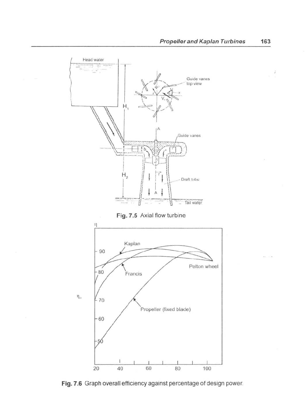
H
is
effective head H =
1-1,
+
1-12
as shown
in
Fig. 7.4
of
Kaplan turbine installation.
Fig. 7.5 shows overall efficiency against percentage
of
design power for various turbines.
Propeller
and
Kaplan Turbines 163
Fig. 7.5
Axial
flow
turbine
Kaplan
90
Pelton wheel
70
Propeller
(Fixed
blade)
60
20
40
60
80
100
Fig. 7.6
Graph
overall
efficiency
against
percentage
of
design
power.
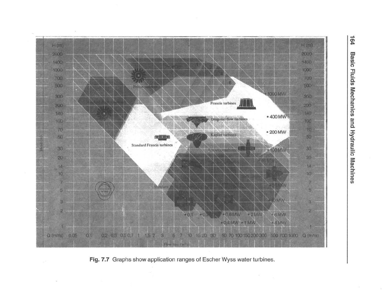
Fig. 7.7 Graphs show application ranges of Escher Wyss water turbines.
....
~
m
I»
UI
c;"
"T1
2"
c:
UI
3:
CD
o
:::T
I»
;:,
c:;.
UI
I»
;:,
Q.
:J:
~
iil
5.
c:;.
3:
I»
o
2:
;:,
CD
UI
Propeller
and
Kaplan Turbines 165
The characteristic curve for the axial flow Kaplan turbine
is
similar
to
radial
flow
francis
turbine. The Pelton efficiency curve
is
flatter but maximum efficiency
is
lower than Francis
turbine. Kaplan has better characteristics than propeller type.
The two mcthods
of
determining specific speed ofpropelkr/Kaplan turbine
is
given bclow:
and
NJP
Ns
=
--5
-
H'(
Fig. 7.6 shows application ranges
of
Escher water turbines. The Pelton turbines are
"
divided into two ranges. The minimum head
of
50-700 m and head
of300-1400
m with low
flow rate. Kaplan turbine works
from
2-20 m with high flow rate developing maximum
power
of
about
100
M
W.
The francis
turbin~
has a big range from 20-300 m and maximum
power
of
100 MW.
7.4 Twisted Blades
The Kaplan turbine aerofoil type propeller blades are long and the radius
at
the hub and tip
varies considerably. The inlet and exit velocity diagrams change at every section
of
the
blading. Therefore blade
is
divided into several domain and calculations made
for
every
section with the inlet angle
a, remaining same, Inlet and exit blade angles
~,
and
f3
2
change
from hub to tip.
Euler's equation
is
re-written
as
E
= .
u_
-=-
( V
-'C
h
,,-v
-
_
V
=
~
w,-,-)
- as V
2w
= 0,
g
we
have
. =
uV(w
=
wR
V
=
(~l(RV
)
E .
Iw
Iw
g g . g
.
..
.. (7.9)
166 Basic Fluids Mechanics and Hydraulic Machines
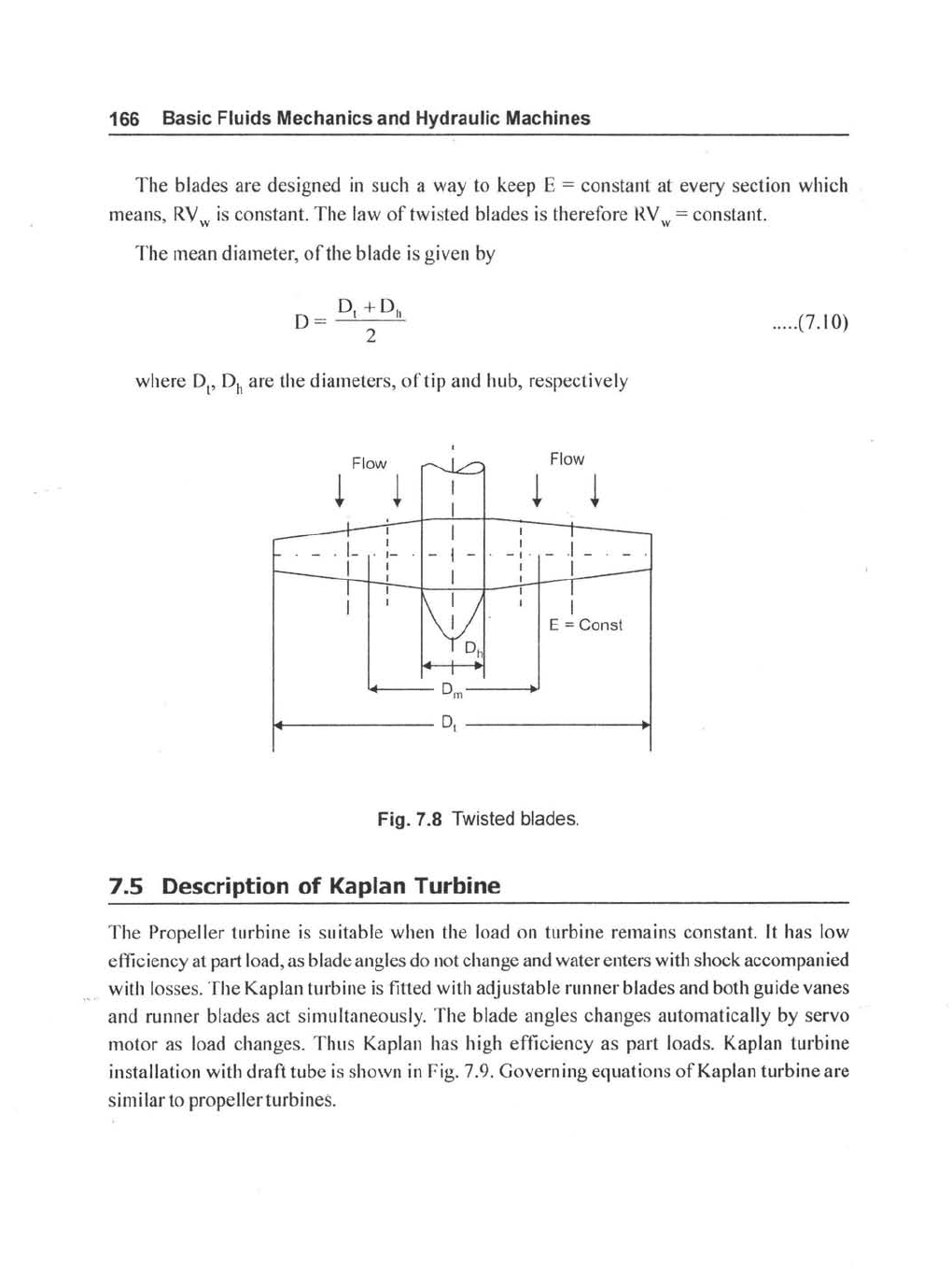
The
blades
are
designed
in
such a way to keep E =
constant
at every section which
means,
RV
w is constant.
The
law
of
twisted blades is therefore
RV
w = constant.
The
mean diameter,
of
the
blade is given by
..... (7.10)
where
D
t
,
Dh
are the diameters,
of
tip
and
hub, respectively
Flow
Flow
~ ~
~
~
. I-
I
I
E = Const
'+---D
m
--~
~-----------
DI
--------~
Fig. 7.8 Twisted blades.
7.5 Description
of
Kaplan Turbine
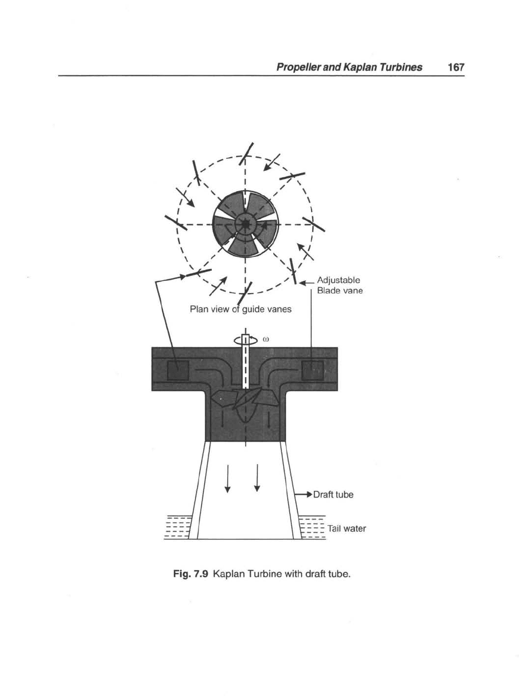
The
Propeller turbine
is
su itable when the load
on
turbine remains constant.
It
has low
efficiency at part load, as blade angles do not change and water enters with shock accompanied
with losses.
The
Kaplan turbine is fitted with adjustable runner blades and both guide
vanes
and
runner blades act simultaneously.
The
blade angles
changes
automatically by servo
motor
as load changes.
Thus
Kaplan has high efficiency as part loads. Kaplan turbine
installation with draft
tube
is
shown in Fig. 7.9.
Governing
equations
of
Kaplan turbine are
sim i lar to propeller turbines.
Propeller and Kaplan Turbines
167
/.,--I-~
)(,
:
~
"-,
,,\
I~
\
I \
~--
--~
\ I
\"
,')(
, " '-1/
'"
~
11: /
,,\
~
Adjustable
7
....
-.I-
-"
Blade vane
Plan view o(gUide vanes
l l
Fig. 7.9 Kaplan Turbine with draft tube.
168 Basic Fluids Mechanics and Hydraulic Machines
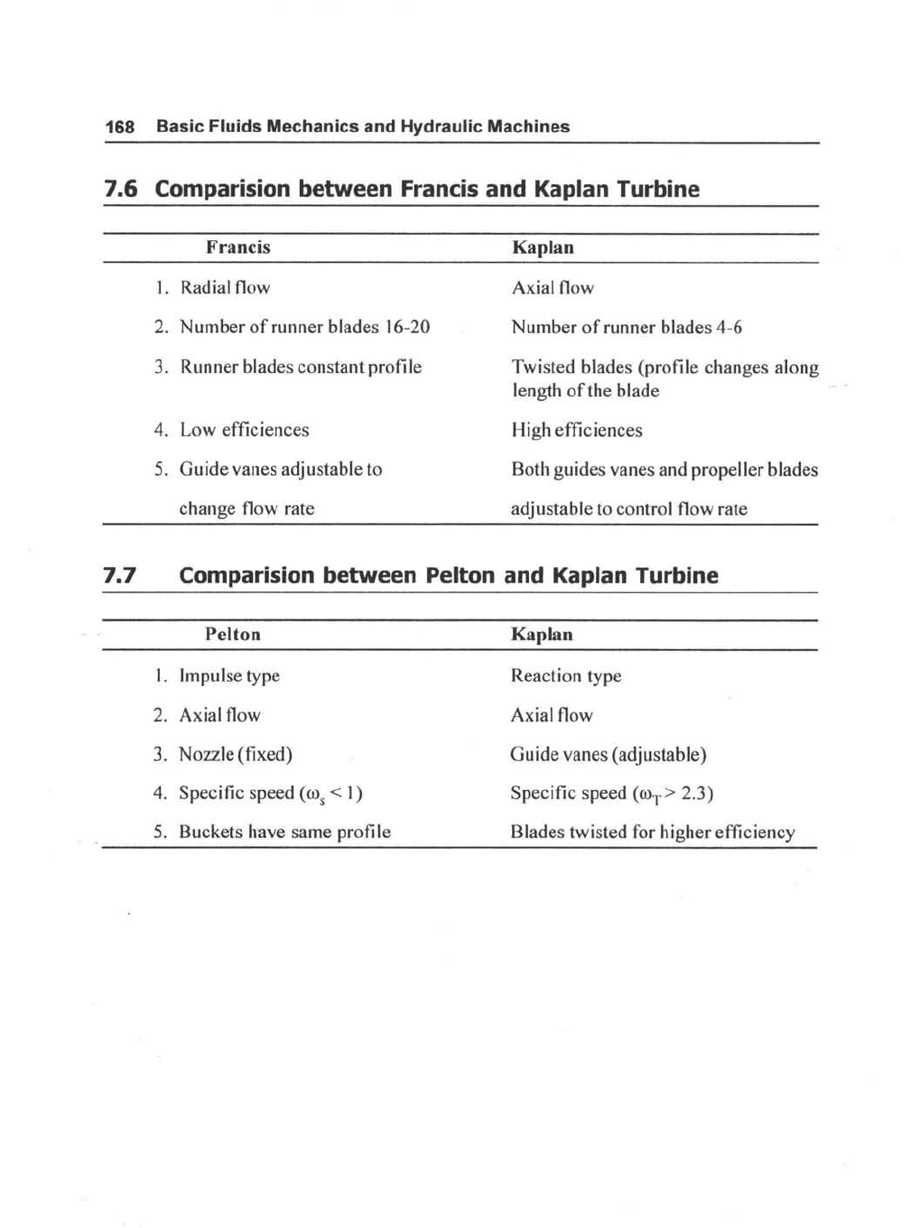
7.6 Comparision between Francis and Kaplan Turbine
Francis
1.
Radial flow
2. Number
of
runner blades 16-20
3. Runner blades constant profile
4. Low efficiences
5.
Guide vanes adjustable to
change flow rate
Kaplan
Axial flow
Number
of
runner blades 4-6
Twisted blades (profile changes along
length
of
the blade
High efficiences
Both guides vanes and propeller blades
adjustable to control flow rate
7.7 Comparision between Pelton and Kaplan Turbine
Pelton
l.
Impulse type
2. Axial flow
3. Nozzle (fixed)
4. Specific speed
(ro
s
<
I)
5.
Buckets have same profi
Ie
Kaplan
Reaction type
Axial flow
Guide vanes (adjustable)
Specific speed
(roT> 2.3)
Blades twisted for higher efficiency
Propeller and Kaplan Turbines
169
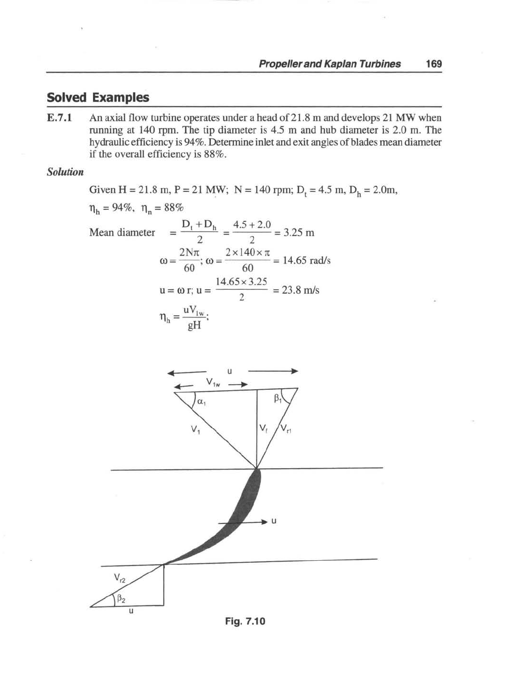
Solved Examples
E. 7.1
An
axial flow turbine operates under a head
of
21.8 m
and
develops
21
MW
when
running
at
140 rpm.
The
tip diameter is 4.5 m
and
hub diameter is 2.0 m.
The
hydraulic efficiency is 94%. Determine inlet and exit angles
of
blades mean diameter
if
the overall efficiency is 88%.
Solution
Given H = 21.8 m, P =
21
MW; N = 140 rpm; D
t
= 4.5 m, Dh =
2.0m
,
llh = 94%, ll
n
= 88%
Mean
diameter
4.5 + 2.0
=
2 = 3.25 m
2Nrc
2 x
140x
rc
(0
= -6-0-;
(0
=
60
= 14.65 rad/s
14.65x
3.25
u =
(Or;
u =
2
uV
'11-~
.
'Ih
- ,
gH
Fig. 7.10
= 23.8 m/s