Hussian Z., AbdullahM.Z., AlimuddinZ. Basic Fluid Mechanics and Hydraulic Machines
Подождите немного. Документ загружается.


130 Basic Fluids Mechanics and Hydraulic Machines
The water passes through row
of
fixed guide vanes followed by adjustable guide vanes.
The flow can be varied when the turbine is working at partial loads by changing the cross-
sectional area between the guide vanes. The water then passes through the runner with
radial vanes. The water enters the runner at large radius and leaves the runner blades at a
smaller radius. The interaction between the fluid and runner blades results in torque applied
to the runner. The runner is connected to the driving shaft to drive an electric generator. The
turbine shown in the Fig.
6.1
is vertical type.
The water after doing the work leaves
through the draft tube. It is essentially a diffuser
whose area increases in the direction
of
the fluid flow. As area increases velocity decreases
and pressure rises.
It
produces a negative pressure at turbine exit and thus increases the head over the
turbine which means more power.
There
is
energy loss at various components from the reservoir to the tail race. There is
energy loss in the penstock conveying water to the turbine losses in fixed guide vanes, and
also adjustable guide vanes, and runner vanes. There is also head loss in the draft tube and
residual kinetic energy loss at exit from the draft tube. Fig. 6.2 shows a large spiral casing
of
Francis turbine for pressure testing in the workshop. Fig. 6.3 shows assembly
of
guide
vanes and runner in
Zurick workshop.
Fig. 6.2 Workshop pressure testing of spiral casing in Zurich, Switzerland.

Fig. 6.3
6.3
Analysis
Let
H
Vo
VI
V
2
V
rl
V
r2
u
l
u
2
V
lw
' V
2w
VIP
V
2f
(XI
~I
~2
-
Francis Turbine
131
Runner and guide vane system
in
Zurich works, Switzerland.
Total head available to the turbine
Absolute velocity
of
water at inlet to stationary vanes
Absolute velocity
of
water at exit to ajustable guide vanes
Absolute velocity
of
water at exit to runner vanes
Relative velocity at inlet to runner vane
Relative velocity at exit to runner vane
Peripheral velocity at inlet to runner vane
Peripheral velocity at exit to runner vane
Whirl velocities at inlet and exit
of
runner vane
Flow velocities at inlet and exit
of
runner vane
Guide vane angle
Runner blade inlet angle
Runner blade exit angle

132 Basic Fluids Mechanics and Hydraulic Machines
Fig. 6.4
Inlet and exit velocity diagram.
The inlet and exit velocity diagrams
of
the runner vane is shown in Fig. 6.4.
we have,
2N1t
U
I
=
roR
1
; U
2
=
roR
2
;
and
ro
=
60
The water comes out from the guide vanes at absolute velocity V 1 at an angle 0.
1
to the
direction
of
rotation. The peripheral velocity u 1 is subtracted from V I to give relative velocity
Vrl
at angle
~I
to the direction
of
rotation is obtained.
At exit the water leaves the runner blade at relative velocity V
r2
which makes an angle
~2
with the direction
of
rotation. Superimposing u
2
absolute velocity V 2 is obtained.
Euler's head is given by
E=
..... (6.1)
If
the whirl velocity at exit is zero, V
2w
= 0, which means that velocity V 2 has no horizontal
component or 0.
2
= 90°, then Euler's eq. 6.1 for maximum efficiency is given by
..... (6.2)

y~
In
such a case flow velocity at exit Y
21'
= Y 2 '
tan132
=
--
u
2
detennined.
Francis Turbine 133
_ Y
2f
so that
13
2
can be
u
2
The energy distribution through a hydraulic reaction turbine is shown
in
Fig. 6.5.
Head race
_____
........
__
hlp
__
-,
~------+
hg
t----....L..--h
r
H
Tailrace
Fig. 6.5 Energy distribution through reaction turbine.
Net
head available H across the turbine
is
the difference
in
total head between inlet
flange (exit
of
penstock) and tail race water level
Po
y
2
0
- Total head
at
inlet = - +
--
+ z
y 2g 0
P
y2
- Total head
at
exit =
---.2.
+
_3
+z
y 2g 3
- Net head across the turbine
..... (6.3)

134 Basic Fluids Mechanics and Hydraulic Machines
But P
3
= atmospheric pressure = 0; z3 is tail race taken as datum z3 = 0, thus eq. 6.3
becomes
H =
(Po
+
V~
+zo]-
(Vi]
g
2g 2g
where h
fp
= hydraulic losses in penstock
The
hydraulic efficiency is given
by,
Mechanical efficiency
Overall efficiency
thus
runneroutput
11R
=
runner input
turbine output
11m
=
runner output
power output
110=
hydraulic input
yQE
=~
=
U1V
1w
yQH H gH
P
yQE
P
yQH
Energy developed in the runner in
tenns
of
Euler's head
E
= H -
hIP
-
hg
-
hr
-
hd
where
h
fp
-
hydraulic losses in penstock
hg
- hydraulic losses in guide vanes
hr - hydraulic losses in runner vanes
hd
- hydraulic losses in draft tube
6.4
Draft Tube
..... (6.4)
..... (6.5)
.... (6.6)
A draft
tube
is connected between runner exit and tail race to obtain continuous stream
of
water
between them. It is diverging tube.
The
pressure increases and velocity decreases in
the tube.
The
tail race pressure is atmospheric and runner exit pressure is negative (below
atmospheric).
Then
the
net
head acting
on
the turbine increases.
The
turbine works with a

Francis Turbine 135
larger head and more power
is
developed by the turbine. This is the main advantage
of
installing a draft tube. All Francis turbines will have a draft tube.
Analysis
With references to Fig. 6.5 and applying Bernoulli's equation between point (2) and (3) we
get
P
y2
P
y2
~+~+Z,
=2+_.1
+Z,
+hd
Y 2g - Y
2g
..... (6.7)
where
hl!
represents losses
in
the diffuser also
P3
= atmospheric = 0; the tail race
is
taken
as datum and therefore
Z3
=
o.
Re-writing eq. 6.7 with the above assumptions,
we
have
Also Y
3 < y
2'
and
ifhd
is
neglected,
P2
in
negative.
y
.....
(6.8)
The draft tube produces negative pressure at exit which increases the pressure head
over
the turbine.
(e)
(d)
Fig. 6.6 Types
of
draft tubes.

136 Basic Fluids Mechanics and Hydraulic Machines
Some
of
the types
of
draft tubes are shown
in
Fig. 6.6.
(a) Straight divergent tube
(b) Moody spreading tube
(c)
Simple elbow tube
(d) Elbow tube with circular inlet section and exit rectangular.
6.5 Working Proportions
of
Francis Turbine
Let
B breadth/width
of
runner vane
D
diameter
of
runner
z
number
of
runner vanes
t
thickness
of
runner vane
n
ratio
of
width to diameter
of
runner
X
Flow ratio
~
speed ratio
V
f
flow velocity
~2gH
Jet velocity
B
n = ° The value
ofn
varies from
0.1
- 0.45
v
- Flow ratio X =
r-!:u
its value varies from 0.15 - 0.3
,,2gH
u
- Speed ratio
~
=
~
its value varies from 0.6 - 0.9
,,2gH
- Flow through runner vanes = flow area x velocity
of
flow
Area (inlet)
= (1tO\ -
zt)
B\
= 1tO)
Bl
K\
where k\ is a factor which allows for thickness
of
runner vanes.
Area (exit)
=
(1t0
2
-
zt)B
2
=
1t0
2
B2 K2
where K2 is a factor which allows for thickness
of
runner vanes.

Flow rate
Q =
(1tD
l
- zt
l
)
Bl
V
If
=
(1tD
2
- zt)
B2
V
2f
Q = 1tDlBl
Kl
Vlf
=
1tD2
~
V
2
V
2f
Q =
1tD:
nlKlV
lf
=
1tD~
n
2
~
V
2f
if
Kl
=
~;
V 1f = V
2f;
n
l
= n
2
, then equation becomes
Bl
Dl
=
B2
D2
Francis
Turbine
137
..... (6.9)
The
number
of
runner vanes varies from 16 to 24.
The
number
of
runner vanes should
pe
either one more
or
less than the number
of
guide vanes to avoid periodic impact.
Fig. 6.7 shows the runner
of
Francis turbine. As indicated B is the breadth
of
runner and
D the diameter.
Fig. 6.7 Runner of Francis turbine.
6.6
SpecifiC
Speed
of
Hydraulic Turbines
The
specific speed is a dimensionless parameter associated with a given family
of
turbines
operating at maximum efficiency with known values
of
&Ilgular
velocity
0)
head H, and
power output
P.
The
specific speed is given by
..... (6.9)

138 Basic Fluids Mechanics and Hydraulic Machines
where
(0
=
angular velocity
in
rad/s
p
=
power output
in
Watt
p
density
of
water
in
kg/m)
H
=
head over the turbine
in
meters
g
=
acceleration due to gravity
in
mil
A preliminary selection
ofthe
appropriate type
of
turbine for given installation
is
based
on specific speed
(Or'
Fig. 6.8 shows type
ofthe
runner for different ranges
of
(01"
Impulse 0 -
1;
Axis
of
rotation
COT
Francis 1 - 3.5;
Impulse
0-1.0
Francis
1.0-3.5
Mixed flow 3.5 - 7; Axial flow 7 -
14
Mixed flow
3.5
-7.0
Axial flow
7.0 - 14.0
Fig. 6.8 Various types
of
runners.
The various authors have given different range
of
specific speed
(0'1'
and some are
summarised below.
Author
Pelton
FnlOcis Mixed flow Axial flow
Potter (1977)
0-
1.0 1.0
- 3.5
3.5-7.0
7.0-14.0
Douglas (1995) 0.05 - 0.4
0.4 -
2.2
1.8
- 4.6 also higher
Shames (1992)
0.05 - 0.5 0.4 - 2.5
1.8
- 4.6 also higher
For turbines homologous specific speed
Ns
is
also used, given by the following equation.
I
Np2
(N
s h =
----sT
H74
..... (6.10)
where H
is
in
meters, P the power output
in
kw, and speed N
in
rev/min
of
runner.
On this basis specific speeds
of
different turbines is given
in
Table
6.1
based the book
of
Fluid Mechanics by Arora (2005).
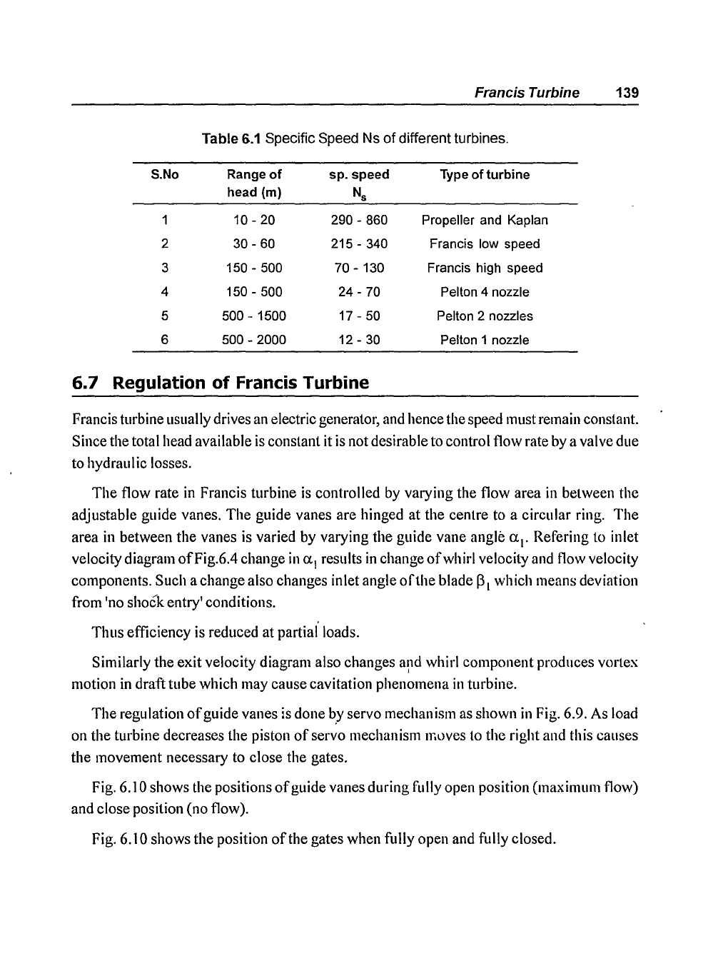
Francis Turbine 139
Table
6.1
Specific Speed Ns
of
different turbines.
S.No
Range
of
sp.speed
Type
ofturbine
head (m)
Ns
1 10 - 20 290 - 860 Propeller and Kaplan
2
30 - 60 215 - 340 Francis low speed
3
150 - 500 70 - 130 Francis high speed
4
150 - 500 24 - 70 Pelton 4 nozzle
5
500 - 1500
17 - 50 Pelton 2 nozzles
6
500 - 2000 12 - 30 Pelton 1 nozzle
6.7 Regulation of Francis Turbine
Francis turbine usually drives an electric generator, and hence the speed must remain constant.
Since the total head available
is
constant it is not desirable to control flow rate by a valve due
to hydraulic losses.
The
flow rate
in
Francis turbine
is
controlled
by
varying the flow area
in
between the
adjustable guide vanes.
The
guide vanes are hinged
at
the centre to a circular ring.
The
area
in
between the vanes is varied by varying the guide vane angle u
1
•
Refering to inlet
velocity diagram ofFig.6.4 change
in
u
1
results
in
change
of
whirl velocity and flow velocity
components. Such a change also changes inlet angle
of
the blade
[31
which means deviation
from 'no
shock entry' conditions.
Thus efficiency is reduced at partial loads.
Similarly the exit velocity diagram also changes and whirl component produces vortex
I
motion
in
draft tube which may cause cavitation phenomena
in
turbine.
The
regulation
of
guide vanes is done by servo mechanism as shown
in
Fig. 6.9. As load
on the turbine decreases the piston
of
servo mechanism
Ir,l>ves
to the right and this causes
the movement necessary to close the gates.
Fig.
6.10 shows the positions
of
guide vanes during fully open position (maximum flow)
and close position (no flow).
Fig.
6.10 shows the position
of
the gates when fully open and fulIy closed.