Hussian Z., AbdullahM.Z., AlimuddinZ. Basic Fluid Mechanics and Hydraulic Machines
Подождите немного. Документ загружается.

150 Basic Fluids Mechanics and Hydraulic Machines
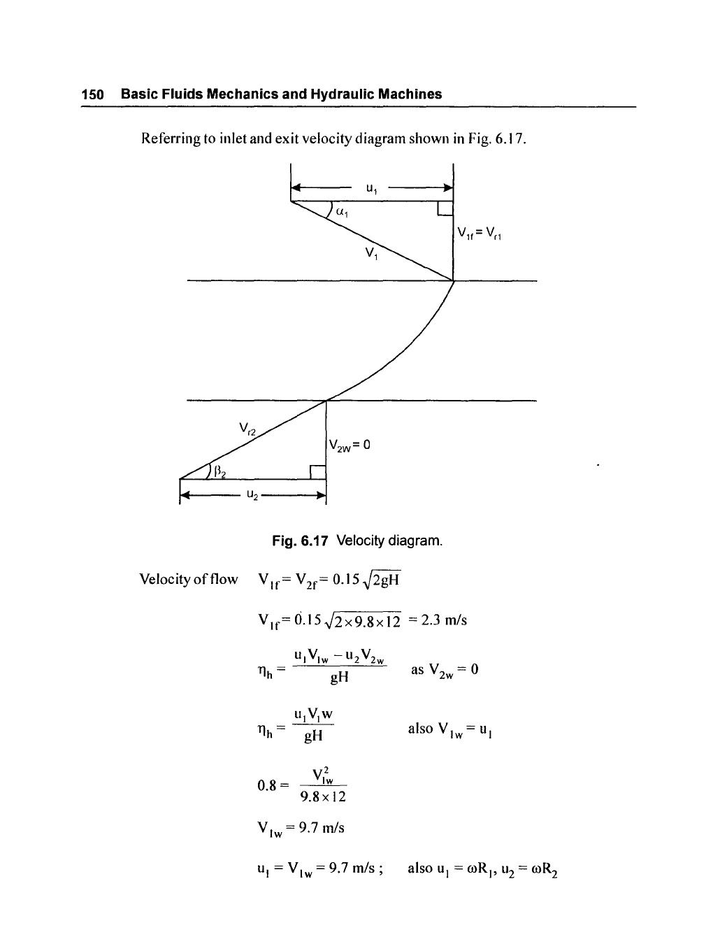
Referring to inlet and exit velocity diagram shown
in
Fig. 6.17.
Fig. 6.17 Velocity diagram.
V
It
,=O.lS.j2x9.8x12
=2.3m/s
U1V
1w
-U
2
V
2w
YJh
= gH
U1V1W
YJh=
gH
0.8=
VI~
9.8x12
V
1w
= 9.7 m/s
as V
2w
= 0
Francis
Turbine
151
R7
I
U
2
=U
I
x R
=9.7x-
=4.85m/s
I 2
V
7r
2.3
tan
~12
=
---
= - = 0.474
u 2 4.85
VII'
2.3
tan a = - =
--
= 0.237
I u
l
9.7
U
I
= 13°
E.6.S
A Francis turbine has
the
following data:
SO/lition
Flow rate 0.4
111
3
Is,
head = 92 m, runner speed 1260 rev/min.
The
guide vane
angle
20°, the radius at inlet = 600 mm, width
of
vanes
30
mill. Determine the
shaft power, hydraulic efficiency and specific speeds
(w
T
'
N
r
).
Assume radial
discharge.
Given
N = 1260 rpm, Q = 0.4 m
3
/s, H = 92 m, u
l
= 20°;
RI
=
600
mm,
BI
=
30
mm
Torque produced by
the
runner
T =
~
V I w R I -
~
V 2w
R2
T =
Qp
V
lw
RI
as V
2w
= 0
also
Q =
1tD
I
B
I
V
If
2x600
30
..
0.4 =
1t
x
x
x
VII'
1000 1000
V
11'=
3.5 mls
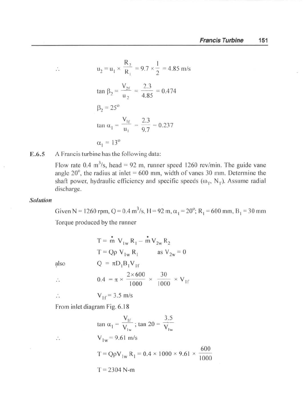
From inlet diagram Fig. 6.
18
VII'
3.5
tan U = - . tan 20 =
----+--
I V
lw
' V
lw
V
lw
=9
.
61
mls
600
T=QpV
lw
R
I
=O.4
x
1000x9
.
61
x 1000
T =
2304
N-m
152, Basic Fluids Mechanics and Hydraulic Machines
U
1
----l~
1+---
V
1W
----l~
Fig. 6.18
Inlet
diagram.
Shaft power = T x
00
where
2Nn
2x1260x1t
00=
--
·
00=
60 ' 60
= 131.1 radls
2304x
2x1260x
1t
Shaft power
=
60 = 304 kw
Overall efficiency
shaft power
304
= hydraulic power = 360 = 0.84
=84
%
ooJP/P
Specific speed
CUr
=
(gH)
5/4
2x
1260x
1t
00
= 60 = 131.8 radls, substituting proper values
131.8
304x10
3
1000
CUr
=
(9.8x92)
%
CUr
= 0.46
N
JP
1260.J3Q4
N
s
= H% = 92%
=76.9
Francis Turbine
153
Problems
P.6.1 Turbines are designed to develop 20,000 kw while operating under a head
of
20 m
and speed
of
60 rev/min. What type
of
turbine is best suited for thier purpose.
Estimate the flow rate needed.
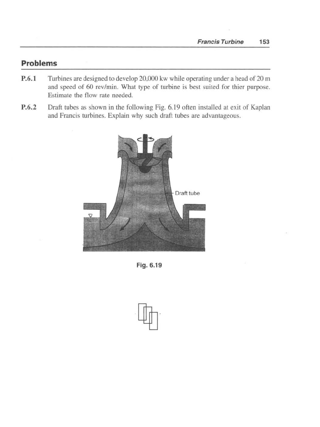
P.6.2 Draft tubes as shown in the following Fig. 6.19 often installed at exit
of
Kaplan
and Francis turbines. Explain why such draft tubes are advantageous.
Fig. 6.19

"This page is Intentionally Left Blank"
CHAPTER
- 7
Propeller
and
Kaplan
Turbines
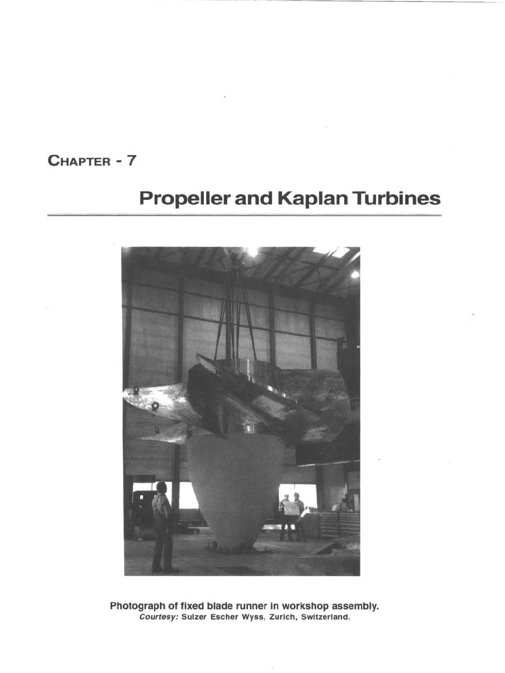
Photograph
of
fixed blade runner in
workshop
assembly.
Courtesy:
Sulzer
Escher
Wyss
,
Zurich,
Switzerland
.

"This page is Intentionally Left Blank"
Propeller and Kaplan Turbines 157
7.1 Introduction
It
has been mentioned
in
the previous chapters that the power developed
by
a hydraulic
turbine
is
the product
of
head available and /low ratc. Pelton turbine
is
suitable for high head
and
low
flow ratcs. Francis turbine
is
suitable for medium head
~nd
medium discharge.
Pelton turbine
is
classitied as impulse and Francis as reaction. Pelton
is
axial flow and
Francis
is
radiaillow. Now we deal with two other axial flow turbines,
low
head and high
discharge, namely,
Propeller and Kaplan turbines. Basically there
is
not much dilTerence
between the two turbines.
In
kaplan turbine both the guide vanes and runner blades are
adjustable with load thus maintaining high efficiency. The blade adjustments are made
simultaneollsly to accommodate changing conditions. Kaplan turbines have reached
efficiencies between 90-95%. Also more than
100
MW
can
be
developed from a single
unit.
In
the propeller type only guide vanes are adjustable with fixed runner blades. Both the
turbines are reaction type and
ax
ial
flow.
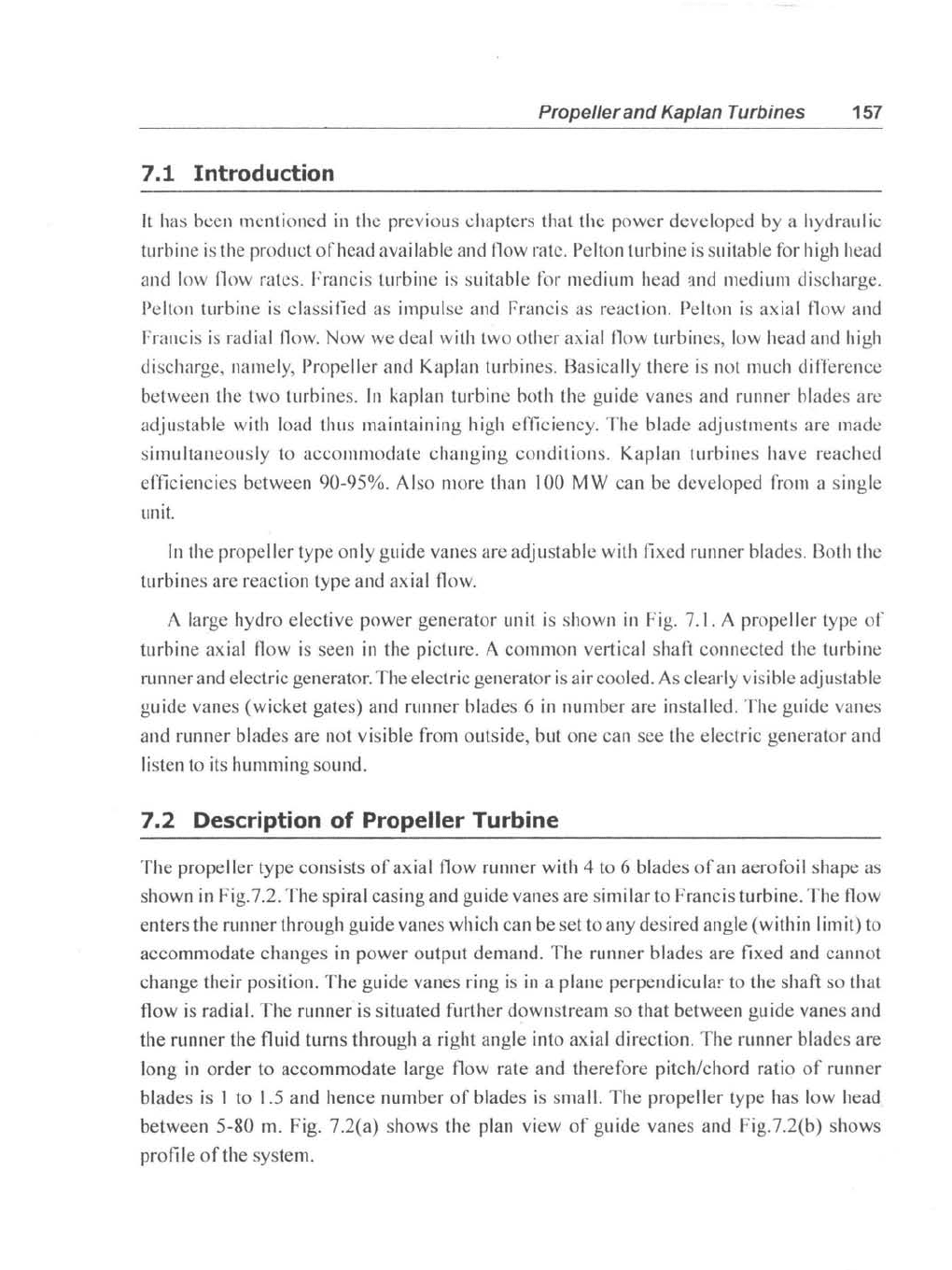
A large hydro elective power generator unit
is
shown
in
Fig.
7.1
. A propeller type
of
turbine axial flow
is
seen
in
the picture. A common vertical shaft connected the turbine
runner and electric generator. The electric generator
is
air cooled.
As
clearly visible adjustable
guide vanes (wicket gates) and runner blades 6
in
number are installed. The guide vanes
and runner blades are not visible from outside, but one can see the electric generator and
listen to
its
humming sound.
7.2 Description
of
Propeller Turbine
The propeller type consists
of
axial flow runner with 4 to 6 blades
of
an aerafoil shape
as
shown
in
Fig. 7.2. The spiral casing and guide vanes are similar to Francis turbine. The flow
enters the runner through guide vanes which can
be
set to any desired angle (within limit) to
accommodate changes
in
power output demand. The runner blades are fixed and cannot
change their position. The guide vanes ring
is
in
a plane perpendicula!' to the shaft so that
flow
is
radial. The runner
is
situated further downstream so that between guide vanes and
the runner the fluid turns through a right angle into axial direction. The runner blades are
long
in
order to accommodate large flow rate and therefore pitch/chord ratio
of
runner
blades
is
1 to
1.5
and hence number
of
blades
is
small. The propeller type has
low
head
between
5-80
m.
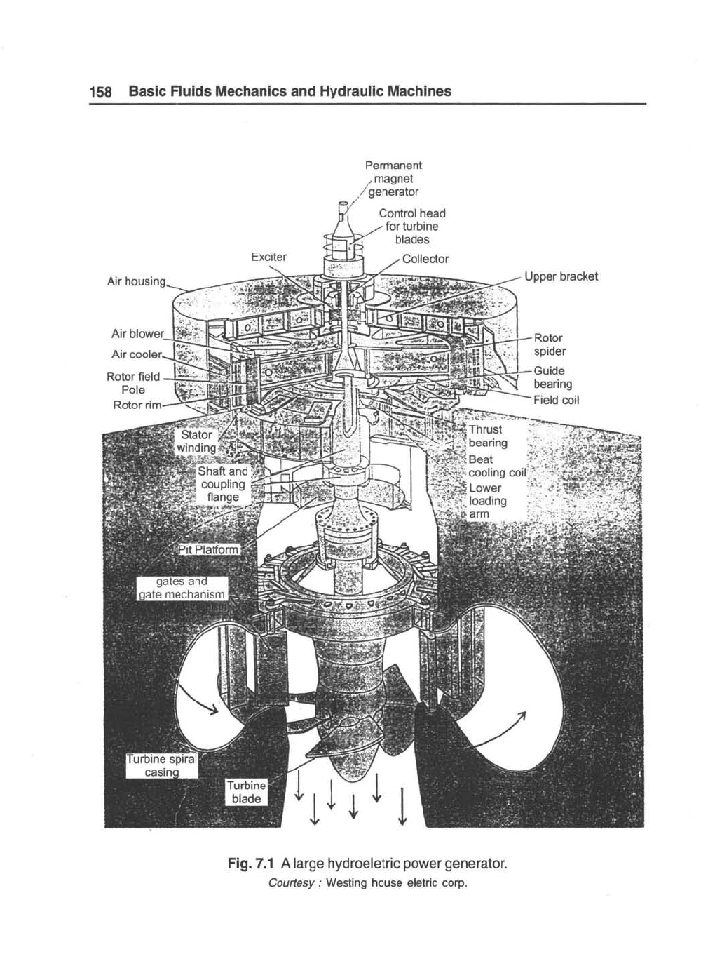
Fig. 7.2(a) shows the plan view
of
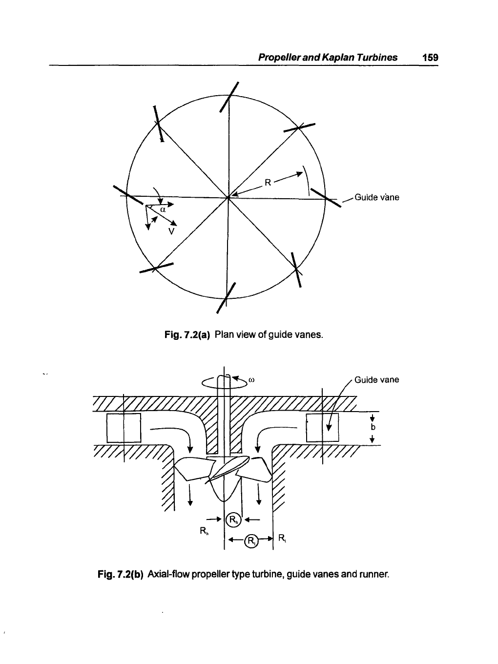
guide vanes and Fig.7.2(b) shows
profile
of
the system.
158 Basic Fluids Mechanics and Hydraulic Machines
Permanent
magnet
generator
Fig.7.1 A large hydroeletric power generator.
Courtesy:
Westing house eletric corp.
Upper bracket
Propeller and Kaplan Turbines
159
I""~---'r----*~------":~~
..----Guide
vane
Fig.7.2(a)
Plan
view of guide
vanes.
+
b
+
Fig. 7.2(b) Axial-flow propeller type turbine, guide vanes
and
runner.