Kothari D.P., Nagrath I.J. Modern Power Systems Analysis
Подождите немного. Документ загружается.

t
From
Eq.
(11.15),
we
get
-
jJi
n,
4+22+Zl
\.
Knowing
l,-trwe
carl
calsqld{e
v,,,
and, vorfromwhich
vsltages
at
the
fault,
I'--
!
-
J'-uo
u
L
Z,*2"+zf
t+22+
(
1 1.18)
be found.
(1
1.19)
(r
1.20)
If the
fault
occurs
from
loaded
conditions,
the positive
sequence
network
can
be
modified
on
the
lines
of
the
later
portion
of
Sec.
1r.3.
11.5
DOUBLE
LrNE-TO-cRouND
(Lrc)
FAULT
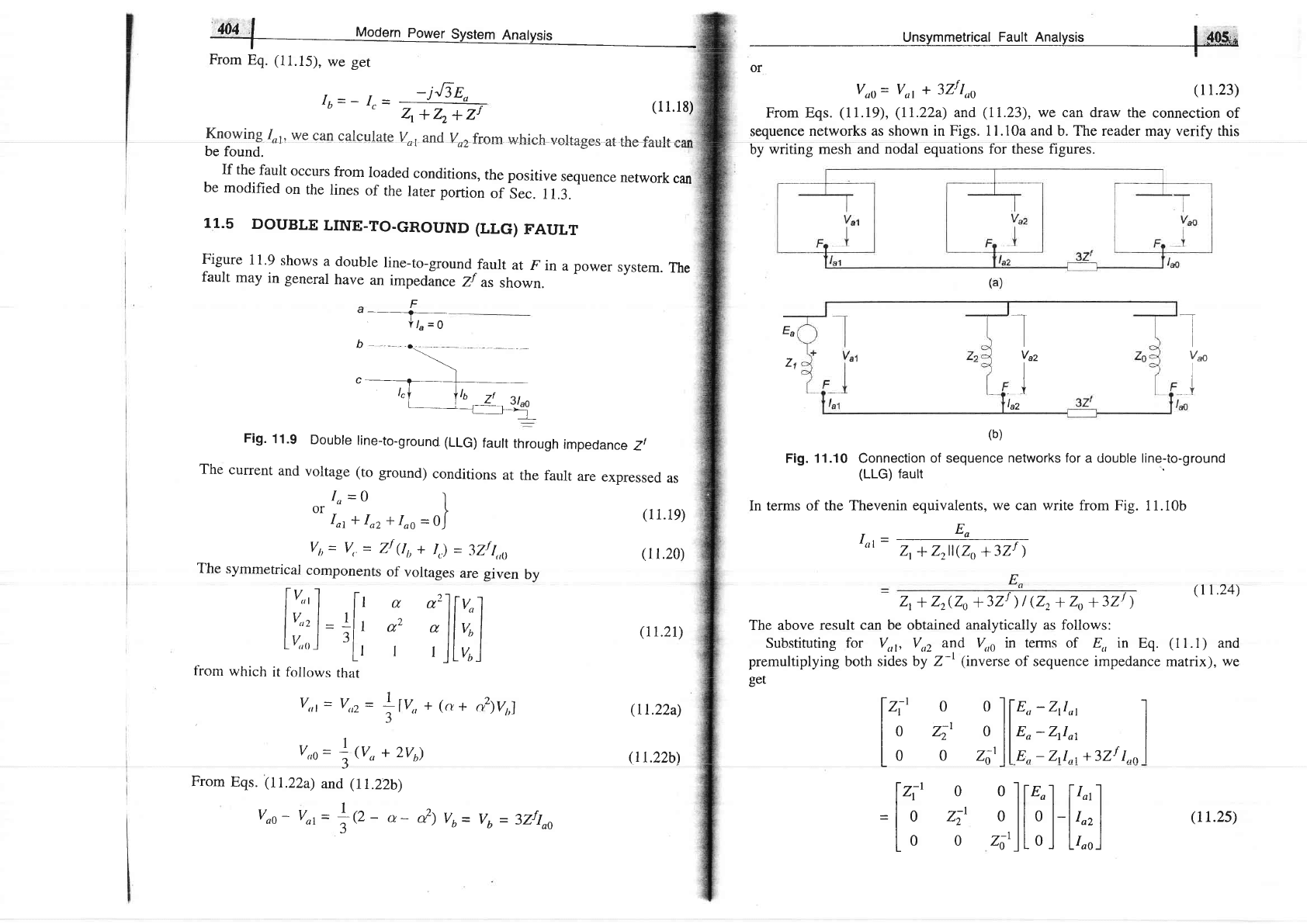
Figure
1
1.9
shows
a
doubre
line-to-ground
fault
at
F
in
a
power
system.
The
fault
may
in general
have
an
impedance
Zf
as
shown.
tr
a-
a
Y/u=9
b-
-,..\.
_.__
|
r"l
t'o
z!
t'"o
|
___
_,__r:]tr"
Fig.
11.9
Double
line-to-ground.
(LLG)
fault
through
impedance
Zl
The
current
and
voltage
(to
ground)
conditions
at
the
fault
are
expressed
as
Io=o
l
ot
i",
+
Io,
+ I"o
=o|
V,,=
V,
=
Zf
(lt,
+
Ir)
=
37rf
1,,r,
The
symmetrical
components
of
voltages
are given
by
l!:'1
[r
a
"']lr.l
l!:'l=
*l
'
a2
o
llvu I
1"v,,,)
,l_l
I
rll,ur)
fiom
which
it follows
rhat
v,,t
=
V.z
=
Llv,,
+
(a
+
r11V,,1
3"'
v,,o=
1""
+
2vu)
From
Eqs.
(11.22a)
and
(t
I.Z2b)
voo-
vot=
tr,
-
,r-
&1
vu=
vt
=
3zfloo
(rr.21)
(Il.22a)
(rr.22b\
Unsymmetrical
Fault Analysis
I SQt*
--_1
or
Voo=
Vot
*
3Zf
Ino
(
l 1.23)
From Eqs.
(11.19), (ll.22a)
and
(11.23),
we can draw the
connection of
sequence
networks as shown in
Figs.
11.10a
and
b. The reader
may
verify
this
by
writing mesh and
nodal equations for these figures.
(b)
Fig. 11.10 Connection
of sequence
networks for
a double line-to-ground
(LLG)
fault
ln terms of the
Thevenin equivalents,
we
can
write
from Fig.
11.10b
I.=
Eo
,l-@
En
(11.24)
zt
+
z2(zo
*3zI
)
I
(22
+
zo
+
3zt
)
The above result
can be obtained
analytically
as follows:
Substiruting
for Vut, Vuz and V,* in terms of E,,in
Eq.
(11.1)
and
premultiplying both sides
by Z-t
(inverse
of sequence
impedance
matrix),
we
get
I
I
Vss
I
+
I
Vaz
:1
laz
Ea
Z1
lt;'
ol[r,,-ztrut
I
I
o z;' o
lln,-2,r", I
I
o o z;'
ll
E,,
-
2,r,,, +3zf I,,nl
'=17'
;,
ilt?l
l';"1
Io
o zot)Lo)
Lr,o_J
(rr.2s)
From
Eq.
(11.22a),
we
have
Eo-
Ztlot=-
Zzloz
Substituting
loz=
-
(Ior
+
Io)
fsee
Eq.
(11.19)]
Eo-
Zrlot=
Zz(Ior
+
Ios)
or
I ^=
Eo
-(
zt+z'\'
'uo-
,-l
,"
1"'
Substituting
this
value
of
Ioo
in
Eq.
(rr.26)
and
simplifying,
we
finally
get
f
"l
=
If the
fault
takes
place
from
loaded
conditions,
the
positive
sequence
network
will
be
modified
as
discussed
in
Sec.
11.3.
r-
---
-----
-
-
l
i
e+tflP.f
;;!utrl,,r|
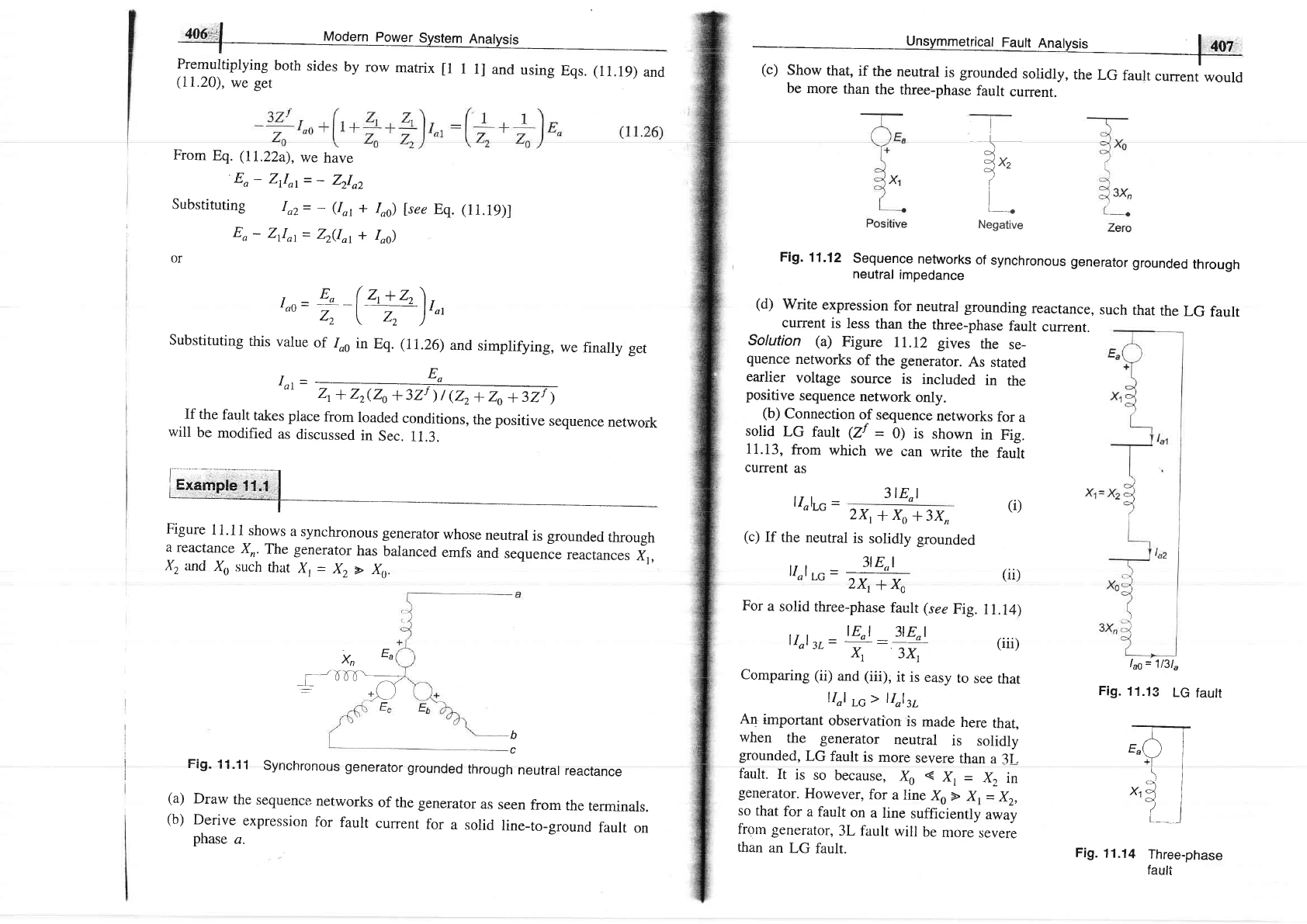
Figure
1 1.1
1 shows
a
synchronous
generator
whose
neutral
is
grounded
through
a
reactanca
Xn.The
generator
has
balanced
emfs
and
sequence
reactances
X1,
X.,
and
Xu
such
that
X,
=
Xz
> Xo.
406t'l
Modern
powe1_syglgll
4!g!yg!s
1-.gltiitiUying
both
sides
by
row
marrix
tl
1
1l
and
using
Eqs.
(11.19)
and
(1I.20),
we ger
xn
Ea
----l'FJf[\--
|
"""
.--\"/
::/)
+)-
)
b
c
Fig'
i
i.i
i
Syne
hronous
generator
grounded
through
neutral
reactance
(a)
Draw
the
sequence
networks
of the
generator
as
seen
from
the
terminals.
(b)
Derive
expression
for
fault
current
for
a
solid
line-to-ground
fault
on
phase
a.
be
more
than
the
three-phase
fault
current.
Fig.
11.12
Sequence
networks
of
synchronous
generator
grounded
through
neutral
impedance
(d)
Write
expression
for
neutral
grounding
reactance,
current
is
less
than
the
three-phase
fault
current.
Solution (a)
Figure
11.12
gives
the
se-
quence
networks
of
the
generator.
As
stated
earlier
voltage
source
is
included
in
the
positive
sequence
network
only.
(b)
Connection
of sequence
networks
for
a
solid
LG
fault
(ZI
=
0) is
shown
in
Fig.
11.13,
from
which
we
can
write
the
fault
current
as
ll)rc
-
3l E,l
zxt+&,*3X,,
\
O<
lx,
?
i
l.
Negative
such
that
the
LG
fault
(i)
(c)
If
the
neutral
is
solidly
grounded
llol
LG
=
=
3l E"l
2\+xc
For
a
solid
three-phase
fault
(see
Fig.
I
Eol
_
3lE"l
lI)rr=;::t
Comparing
(ii)
and
(iii),
it is
easy
to
llol
Lc>
llol3L
An
important
observation
is
made
here
that,
when
the generator
neutral
is
solidly
grounded,
LG
fault
is
more
severe
than
a 3I_
fault.
It
is
so
because,
Xo
*
Xr
=
X,
in
generator.
However,
for
a line
Xo
D
Xt
=
Xz,
so
that
for
a
fault
on
a line
sufficiently
away
frorn
generator,
3L
fault
will
be
ntore
severe
than
an
LG
fault.
lqs=
1131.
Fig.
11.13
LG
fautt
n
E"()
I
ft l
\l
ql
Xt'4
I
7i
L__
l
Fig.
11.14
Three-phase
fauft
(ii)
1
1.14)
(iii)
see
that
usqelrl@
(d)
with
generator
neu,tral
grounded
through
reactance,
comparing
Eqs.
(i)
and
(iii),
we
have
for
LG
faurt
current
to
be
less
than
3L
fault
3l
E,l
24
+
Xo
+3X,
2X,
+
Xo
+
3Xn>
3Xl
*^,
I(xr
-
xo)
J
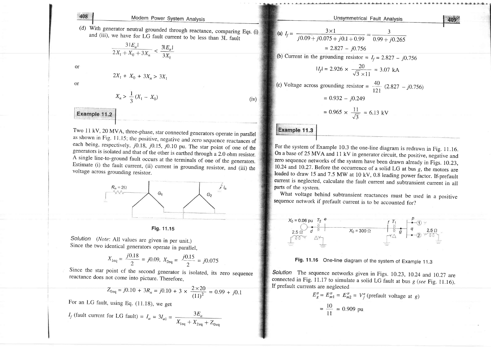
Fig.
11.15
Solution
(Note:
All
values
are given
in per
unit.)
Since
the
two
identicar
generators
operate
in paralrer,
Two
11
kV,
20
MVA,
three-phase,
star
connected
generators
operate
in parallel
as
shtrwn
in
Fig'
ll'15,
thc
positive,
negativc
and-zero
sequence
reactances
of
each
being,
respectively,
j0.1g,
j0.r5,7o.10
pu.
The
star point
of
one
of
the
generators
is
isolated
and
that
of
the
other
is
earthed
through
a 2.0
ohm
resistor.
A
single
line-to-ground
fault
occurs
at
the
terminals
of
one
of
the generators.
Estimate
(i)
the
faurt
current,
(ii)
current
in
grounding
resistor,
and
(iii)
the
voltage
across
grounding
resistor.
408
(iv)
i;;;ili",i:rl
Xr.o
=
=
i0.0g,
Xr"q=
t-'#
=
j0.075
Since
the
star
point
cf
the
second
generator
is
isolated,
its
zero
sequence
reactance
does
not
come
into
picture.
Therefore,
Zo"q=7O.10
+3Rn=j0.10+3x
4:+
=0.99+
i0.1
(ll)',
r-
For
an
LG
fault,
using
Eq.
(11.1g),
we
ger
3E
j0.18
Iy
(fault
current
for
LG
fault)
-
Io
=
3lo,
=
Xt"o
+
Xz"qlZo",
-a.1.-.4s^&g...-'r}.}.*'*.3a---}l!-}-}.}'Qtpt|
Unsymmetrical
Fault
Analysis
l'i
tltrffi
3x1
f
J
=
0.965
=
6.13
kV
For the
system
of
Example
10.3
the
one-line
diagram
is
redrawn
in
Fig.
I 1.16.
On
a base
of
25
MVA
and
I
1 kV
in generator
circuit,
the positive,
nega"tiue
and
zero
sequence
networks
of the
system
have
been
drawn
already
in
Figs.
10.23,
10.24
and
10.27-
Before
the
occurrence
of
a
solid
LG
at
bus g,
the
motors
are
loaded
to
draw
15
and
7.5
MW
at
10
kV,
0.8
leading
power
factor.
Ifiprefault
current
is
neglected,
calculate
the
fault
current
and
subtransient
current
in
all
parts
of the
system.
(a)
Ir=If
-
:
J
-'AAA r :AA4E,
.n
r
j
0.0e
+
j0.07
s+
j0.1
+
0.9e
0.99
+
j0.26s
=
2.827
-
j0.756
(b)
Cunent
in
the
grounding
resisror
=
If
=
2.g27
_
j0.756
llrl
=
2.926 x
-:L-
=
3.07
kA
"
J3
xll
(c)
Voltage
across
grounding
resisror
=
*
e.g2i
-
j0.756)
12r
-
0.932
-
j0.249
What
voltage
behind
subtransient
sequence
network
il prefault
current
Xo
=
0.06
pu
Tz
e
(H+----
2.5A-
d
)(
|
Xo
=
300
fl
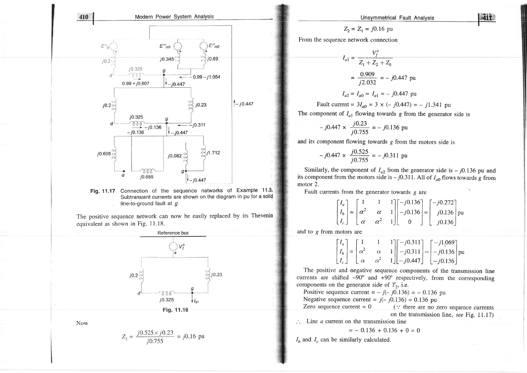
Fig.
11.16
one-rine
diagram
of
the
system
of Exampre
11.3
solution
The
sequence
networks
given
in
Figs.
10.23,
10.24
and
r0.2i
are
connected
in
Fig.
11.17
to
simulate
a
solid
LG
fault
at
bus g
(see
Fig.
11.16).
[f nreforrlt nrrffanfo ara nanlo^+^.i
vurrvrrlD
qrv
rrvSlvvL(/\I
E'l=
E',!,t
=
E',1,2
=
vj
(prefault
voltage
at g)
=
1+
=
o.eoe
pu
reactances
must
be
used
in
a
positive
is
to
be
accounted
fbr'/
.l''.
E"o(
)
f
l0
2:l
(
io'szs
dt
rb-6T--___
410
I
Modern Power
System
Analysis
I
I
l-
io.t+z
------+
-i0.136
-i0.1
36
*_--
-
j0.311
.447
i
0.608 11.712
I
-p.oo,
Fig.
11.17 Connection
of the sequence
networks
of
Example
1 1.3.
Subtransient
currents
are shown
on
the diagram
in
pu
for a
solid
line-to-ground
fault
at
g
The
positive sequence
network
can now
be easily
replaced
by
its
Thevenin
equivalent
as
shown in
Fig.
11.18.
Reference
bus
T
r
--'>
0.99
+i0.607
Now
.
Unsymmetrical
Fautt Anatysir
mbl
T-
Zz=
Zr
=
j0.16
pu
Fiom the
scquence
network
connection
Vf
f_J
'or
-
737;4
=
q'901
=
-
jo.Ml
pu
j2.032
Ioz=
Ioo= Ior
=
-
j0.447
pu
Fault
current
=
3loo
=
3
x
(-
j0.447)
=
-
jL341
pu
The component
of Io,
flowing towards
g
from
the generator
side is
j0.447
x
!:
?:=
=
-
70.136
pu
j0.7ss
and
its
component
flowing towards g
from the
motors
side is
-
jo.Ml
*
i,?s?-s=
=
-
j0.311
pu
j0.7ss
Similarly,
the component
of Io2from
the
generator
side is
-
j0.136
pu
and
its
component
from the
motors side is
-70.311.
All
of
Iosflows
towards g
from
tnotor 2.
Fault
currents
from the
generator
towards g
are
I
r,1
[
r I
rl
[-ro.r30l l-i0.2721
lll.llll
Irul=laz
G rll-io.rr6
l=l
70.136
lpu
Lr.J
lo
u2 rJL
o
j
L
jo.r36j
and to
g
fiom motors
are
[t..] [t
I llf-ro.ltt1
[-.rl,06el
I
tol-
|
a2 a
r
ll
-ro.su
l:l-io.r36lpu
l"ll^ll"ll'l'
L/,J
la
e"
I)L-j0.447J
L-j0.136_l
The
positive
and negative
sequence
components
of the
transmission
line
cunents are shifted
-90"
and +90o
respectively,
from
the
corresponding
components
on the
generator
side of Tr,
i.e.
Positive
sequence
current
=
-
j(-jO.136)
-
-
0.136 pu
Negative
sequence current
-
j(- j0.I36) =
0.136
pu
Zero sequence current
=
0
('.'
there
are
no
zero secluence
currents
on the transmission
line,
see
Frg.
ll.17)
Line a current
on
the
transmission
line
=-Q.136+0.136+0=0
Iu and I,
can be similarly
calculated.
4l:iN
Modern
power
System
Anatvsis
Let us
now calculate
the voltages
behind
subtransient
reactances
to be used
if
the load
currents
are
accounted
for. The per
unit
motor
currents
are:
25x0.909x0.8
136.86
=
0.66
+
j0.495
pu
25x0.909x0.8
=
0.4125
136.86'=
0.33
+
j0.248
pu
Total cuffent
drawn
by
both motors
=
0.99 +
j0.743
pu
The voltages
behind
subtransient
reactances
are
calculated
below:
Motor
1: tr'^'
=
lllt-
r:';::
="ri;Yilii.il
r"
Motor 2:
E!"2
=
l.l:t-,
l';:::iir:tfi
il
r"
Generator, E'{
=
0.909
+
j0.525
x
I.2375136.86"
=
0.52 +
j0.52 =
0.735145. pu
It
may
be noted
that
with
these
voltages
behind
subtransient
reactailces,
the
Thevcnin
equivalent
circuit
will
still
be the
same as
that
of Fig.
11.19.
Therefore,
in
calculating
fault
currents
taking
into
account prefault
loading
condition,
we need
not
calculate
EIy E/ft
and
E(.
Using
the
Thevenin
eqtrivalent
approach,
we can
first
calculate
currents
cauied
by fault
to
which the
load
currents
can
then
be
added.
Thus,
the
actual
value
of
positive
sequence
current
from the generator
.^--.^-l^ rl-- f^--lr !-
ruw:lrus
ule Iault
ls
0.99
+
-j0.743
-j0.136
=
0.99
+
j0.607
and
the
actual value
of positive
sequence
current
from
the motors
to
the fault
ls'
-0.99
-j0.743
-j0.311=
-
0.99
-jr.054
In
this
problem,
because
of
large
zero
sequence
react ance,
load current
is
comparable
with
(in
fact,
more
than)
the
fault
current.
In
a large
practical
system,
however,
the
reverse
will
be
the
case,
so that
it is
normal practice
to
neglect
load
current
without
causing
an
appreciable
error.
For Example
I1.2,
assume
that
the
grounded
generator
is
solidly grounded.
Find
f}ro f^"1+ nrr*a*# ^-J ,,^lr^-^ ^f eL^ l-^^trr^-- -r- - - - r r. r a.
rrrv
rcrlrrL t-tursrrl
auLr
vurLil$tr
ul ttl9
lr€artlly
pllase
IOf
a lfne-to-llne
laUlt
On
terminals
of
the
generators.
Assume
solid
fault
(Zf
-
0).
Solution
For
the
LL
fault,
using
Eq.
(11.I7)
and
substituting
the values
of
X,"u
and
Xr"u from
Example
11.2,
we
get
Unsymmetricat Fault
Anglysis
lll4#hF
F
tua
tal
-
x*q*
Xr",
i0.09
+
i0.075
Using Eq.
(11.15),
we have
1y
(fault
current)
=
Io
=
-i
Now
=
_
j6.06
3X-j6.06):-10.496
Vot
=
Voz
=
Eo
-
Iorxleq
=
1'0
-
(-
j6.06)
=
0.455
Voo=- I^/'o-g
Voltage
of the healthy
phase,
Vo= Vot *
Vnz* Voo
=
0.91
u0.0e)
("'
/oo
=
0)
3or Example 11.2, assume that
the
grounded
generator
is
solidly
grounded.
Find
.he fault current
in
each
phase
and
voltage
of the healthy phase
for a double
ine-to-ground fault on terminals
of the
generator.
Assume
solid
fault
(Zf
-
01.
)olution Using Eq.
(1I.24)
and substituting
the values
of Zp*
Zr"rand Z*,
rom
Example 1l.2,we
get
(note
Zf
=0,
Z0"q=j0.1)
t+70
I_
ral
-
''r-
--;7<?
10.075
x
i
0.10
io.oe.
{: Yj:
^
J::
l:
-
j0.075
+
j0.i0
Vot= Vo2= Vo1= Eo-
Ior Zr.q= 1
-
(-
j7.53)
(/O.09)
=
0.323
_Voz
-
Zr.,
Voo
Zo.,
0.323
I_
ra2-
t-
ta0
-
-
j4.306
j0.07s
0.323 .^
A^
= t1 /1
j0.10
Iu= rllot + alo, + Ioo
=
(-0.5
-/0.866)
(-j7.53)
+
(-O.5
+
_i0.866)
U4.306)
+
j3.23
=
-
10.248
+
j4.842
-
11.334 1154.74'
Ir=
el,r,
+ ozlor*
Ino
=
(-0.s
+
70.866)
(-j7.s3)
+
(-0.5
-j0.866)
(j4.306)
+
j3.23
4!4"
1
Modern
Power
System
Analysis
I
-
10.248
+
j4.842
-
71.334125.28"
Voltage
of
the
healthy
phase,
Vo= 3Vat
=
3
x
0.323
=
0.969
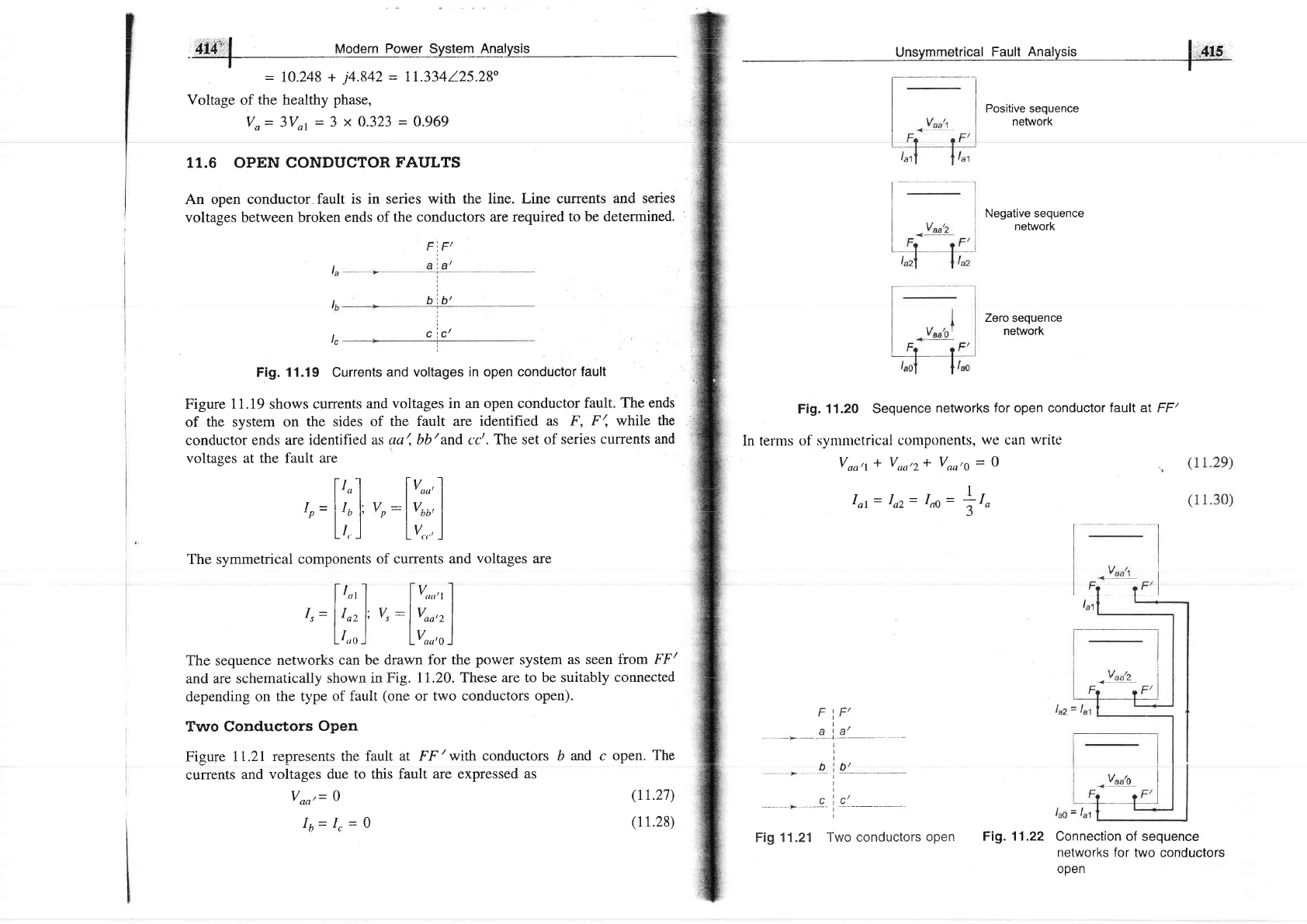
11.6 OPEN CONDUCTOR
FAULTS
An open conductor
fault is in series
with the line. Line currents
and series
voltages between broken
ends of the
conductors are required
to be determined,
lc
cic'
Fig.
11.19
Currents
and
voltages in open conductor
fault
Figure
1
1.19 shows currents
and
voltages
in
an open conductor
fault. The
ends
of the system
on the
sides of
the fault are identified
as F,
F', while the
conductor
ends are
identified
as ua
/,
bb
/
and cc'. The set
of series
currents and
voltages at the fault are
l-l I f v .l
l', I l'""'l
r
-lt,
l:v:lv..,l
'p
l-, 1''P I
oo'l
L/, I
LV,,,
)
The symmetrical
components
of currents and
voltages are
[
/.'
I 1v,,,,,,1
t.
=
|
I^.
l:
v"
:l
v^-,"
I
"
l"'l |
""'l
L/.,, J
lVou'o )
The sequence
networks
can be drawn for the
power
system
as seen from
FF/
and
are schematically
shown
in Fig.
ll.2O. These are to be suitably
connected
depending
on the type
of fault
(one
or two conductors open).
Two Conductors
Open
Figure
lI.2l
represents the
fault at FF
/with
conductors
currents
and voltages
due to this fault
are expressed as
Voo'= 0
16=Ir-Q
b
and
c
open.
The
(rr.27)
(11.28)
Unsymmetrical
Fault
Analysis
|
,415
Positive sequence
network
Negative sequence
network
Fig.
11.20 Sequence
networks
for
open conductor
laull at FF/
[n terms of
symtnctrical
cotnponents,
we can
wrlte
Zero sequence
network
F
IF'
I
I
I
c"c'
I
Fig 11.21 Two
conductors
open
'tD
Vonl
* Voo,2* Vno,g
=
O
Iot= Io2=
Ino-
+1"
Fig.11.22 Connection of
sequence
networks
for two
conductors
open
Onc
Con-luctor
Open
1
Vool=
Voor2=
Voory=
*Voo,
J
Iot*
In + Ioo=0
Equations
(11.33)
and
(1I.34)
suggest
a
parallel
networks
as
shown in
Fie. 1I.24.
la
F
a
t c', c/
,c+-
i
Fig.
11.23
One
conductor
open
tt'6
il
Modern Power
System Anatysis
t
Equations
(11.29)
and
(11.30)
suggest
a series connection of sequence
networks
as
shown in Fig.
II.22.
Sequence
currelrts and voltages
can now be
computed.
For one
conductor
open as
in Fig. 11.23,
the
circuit conditions
require
Vbb,=Vrr,=O
(11.31)
Io
=
O
(11.32)
In terms
of symmetrical components
these
conditions can
be expressed as
(11.33)
(11.34)
connection
of sequence
lao
Fig. 11.24
Connection of sequence
networks for one
conductor
open
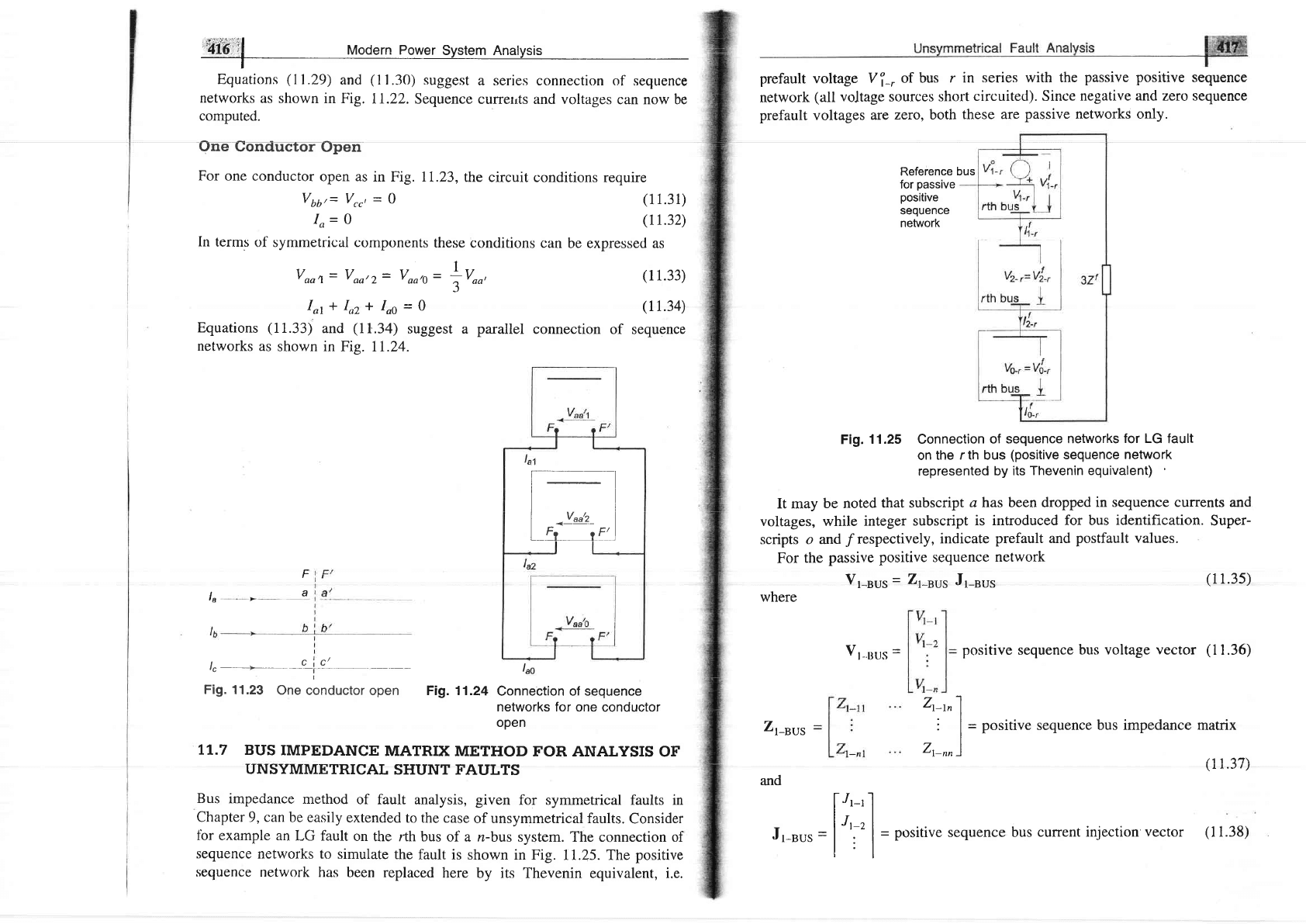
II.7
BUS
IMPEDANCE
MATRIX
METHOD
FOR ANALYSIS
OF
UNSYMMETRICAL
SHUNT
FAULTS
Bus
impedance
method
of fault analysis, given
for symmetrical faults in
Chapter
9,
can
be easily
extended
to the case
of unsymmetrical faults.
Consider
fbr
example an
LG fault
on
the rth
bus of a n-bus
system. The connection of
sequence
networks to
simulate
the
fault is
shown in Fig.
I1.25. The
positive
sequence
network
has
been replaced
here
by its Thevenin equivalent, i,e.
prefault voltage
Vf_.
of bus
r in series
with the
passive positive
sequence
network
(all
voltage sources short
circuited). Since
negative and zero sequence
prefault
voltages
are
zero, both
these are
passive
networks only.
Reference
bus
for
passive
positive
sequence
network
Fig.
11.25 Connection
of sequence
networks
for LG
fault
on
the r th bus
(positive
sequence
network
represented
by its
Thevenin equivalent)
It may
be noted
that subscript
a has been dropped
in sequence currents and
voltages, while
integer subscript
is
introduced for bus
identification.
Super-
scripts o and
/respectively,
indicate
prefault
and
postfault values.
For
the
passive
positive
sequence
network
Vr-"us
=
Zr-nus
Jr-"ut
where
Vt-uus
=
positive
sequence
bus voltage
vector
(1
1.36)
Zr-nus
and
-
positive
sequence
bus impedance
matrix
/1 1 2?\
\L
r.J
t
)
bus cunent
injection vector
(l1.38)
(11.35)
Z-trl
:l
Zt-nn
)
[/'-' I
ltt.'|
=
positive
sequence
l:l
rl
[--l
tl
I
V""'z
I
L-'i--
'
ryl
Jr-sus
=
t4l8 |
todern
power
Svstem
Analvsis
I
Thus
the
passive
positive
seguence
network
presents
an
impedance
Zr_
r,
to the
positive
sequence
current
I{_r.
For
the
negative
sequence
network
Vz-uus
=
Zz_sus
Jz_nus
(11.41)
The
negative
sequence
network
is
injected
with
current
lfr_, at
the rth
bus
only.
Therefore,
nly
at the
(1
1.3e)
sequence
(
1
1.40)
As per
the
sequence
network
connection,
current
-
IJr_,
is injected
o
faulted
rth
bus
of the positive
sequence
network,
we
have
therefore
substituting
Eq.(11.39)
in Eq.
(11.35),
we
can wrire
the
positive
voltage
at the
rth
bus
of the passive
positive
sequence
network
as
V,-,'
=
-
Zr-rrlfr-,
0
0
-,i{
,
0
(1r.42)
The
negative
sequence
voltage
at the
rth
bus
is then
given
by
Yr,=-
zr
rrlf, I
Thus,
the
negative
sequence
network
offers
an impedance
Zr_rrto
the
negative
sequence
current
ltr_,
Sirnilarly,
fbr
the
zero
scqucnce
network
Vu-uu,
=
Zo-sus
J,,-",r,
(11
.44)
Jo-sus
=
0
0
-r{
^
u-r
0
(r
1.46)
Zrr_,.,.
to the
zero
Jz-sus
=
(l
1.43)
(
l l.4s)
and
Vo_,
=
-
Zs_,.rlf
s_,.,
That
is,
the zero
s.equence
network
off'ers
zrn
intpeclance
sequence
cuffent
l'-*r.
From
the
Sequence
network
connection
of Fig.
11.25,
we can
now
-
rf
-
t2-r
vro-,
(rr.47)
2r-,,
*
zz-,,
I
Zo-r,
+3zf
Zl-rr,
Zr-r,
and
Zo-n
other
types
of
faults
can
be
simila*Seomputed
using
in
place of
Zr,
Zrand
Zoin
Eqs.
(1I.7),
(11.17)
and
write
ue
(11.24)
with
E,
-
Vi-,.
Postfault
sequence
voltages
at
any bus
can
now be
computed
by
superposing
on
prefault
bus
voltage,
the
voltage
developed
owing
to the
injection
of
appropriate
sequence
current
at bus
r'.
Foi
passive
positive^sequence
network,
the
voltage developed
at
bus
i owing
to
the injection
of
-
IIr-,
at bus
r is
Vt-r=-
Zr-,Jfr-,
Hence
postfault
positive
sequence
voltage
at
bus I
is
given by
Vl-,=
Vi-,-
Zr-,,fr-,;
i
=
l'
7'
"''
tt
where
prefault
positive
sequence
voltage
at bus
i
Zr-,,
=
irth
component
of
Zt-"ut
Since
the
prefault
negative
sequence
bus
voltages
negative
sequence
bus
voltages
are
given
by
Vf'-'=0+
Vz-r
--
-
zr-,rl'fr-,
where
are
zero,
the
postfault
lr-,,
=
irtlt
colllpollcltt
ol'
Zt-t,,t
Similarly,
the
postfault
zero
sequence
bus
voltages
are
given by
Vd-'
=
-
Zu-''lfu-'';
j
=
l'
2'
"''
tI
where
=
irth
component
tlf
Z9-
sLr.
With
postfault
sequence
voltages
known
at the
buses,
sequence
currents
in
lines
can
be comPr'rted
as:
For
line
uv,
having
sequence
adrnittarlces
yl
-ur,
Jz',u,
and
yo-r,
f
,-rr=
lt-u,
(Vft-u
-
v[-r)
Ifr-rr=
!2-,,r,
(Vt-,,
-
V5-r,)
Ii,r-ur=
Jo-u,
(Vio-,
-
Vfo-rl
Knowing
sequence
voltages
and
currents,
phase
voltages
and
currents
can be
easily
computed
by
the
use
of
the symmetrical
component
transformation
Vr,
=
AV"
Ir,
=
AI,
(11.48)
(
l
r.49)
(
l r.s0)
(
il.s 1)
(
r r.s2)
'i[di;,l
Modern
powSr
Jy$ern_4nglysis
It
appears
at first,
as if
this
method
is
more
laborious
than
computing
fault
currents
from
Thevenin
impedances
of the
sequence
networks,
as it
requires
computation
of
bus
impedance
matrices
of all
the
three
sequence
networks.
It
must,
however,
be
pointed
out here
that
once
the
bus impedance
matriceq
have
been
assembled,
fault
analysis
can
be conveniently
carried
out for
all
the buses,
which,
in
fact,
is
the aim
of a
fault
study.
Moreover,
bus
impedance
matrices
can
be
easily
modified
to account
for
changes
in
power
network
configuration.
For
Example
10.3,
positive,
negative
and
zero
sequence
networks
have
been
drawn
in
Figs.
70.23,
10.24
and
10:27.
Using
the
bus
impedance
method
of
fault
analysis,
find
fault
currents
for
a solid
LG
fault
at
(i)
bus
e and
(ii)
bus
I
Also
find
bus
voltages
and
line
currents
in case
(i).
Assume
the
prefault
currents
to
be zero
and
the prefault
voltages
to
be 1
pu.
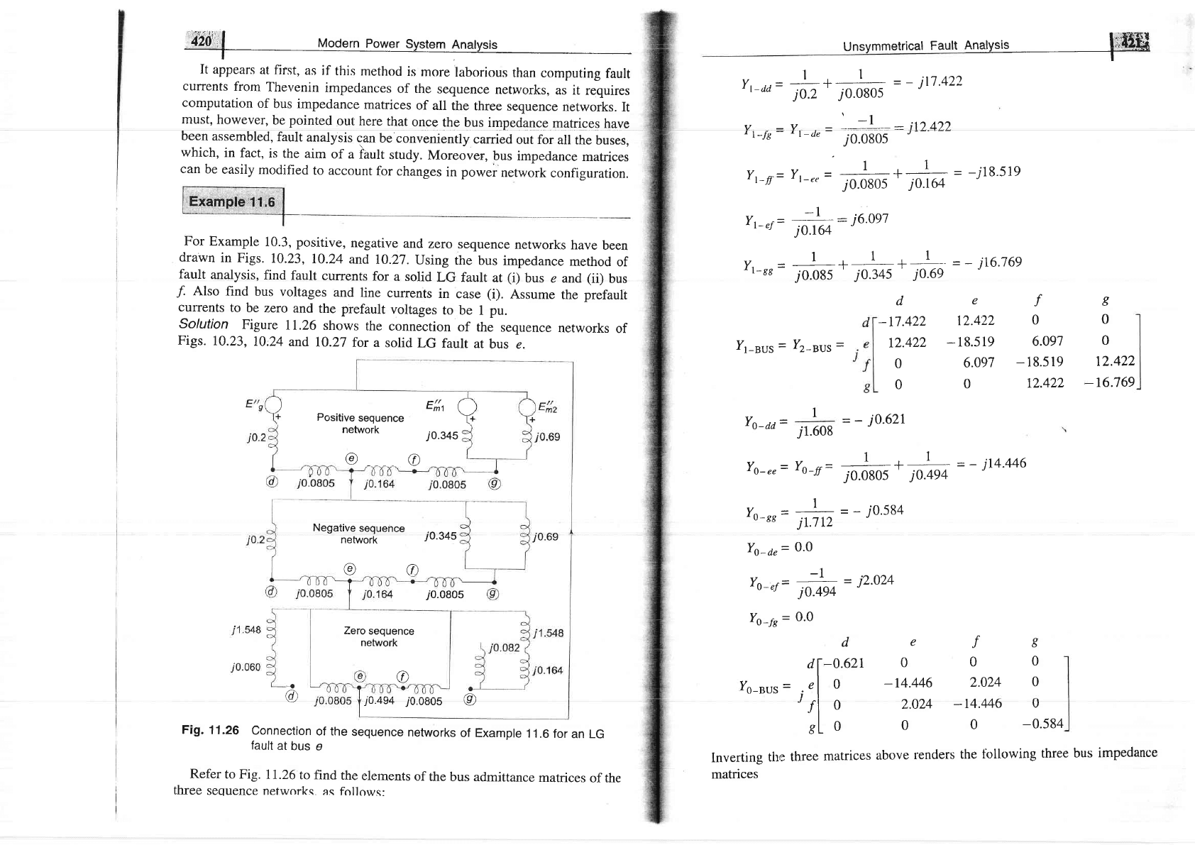
Solution
Figure
11.26
shows
the
connection
of the
sequence
networks
of
Figs.
10.23,
10:24
and
10.27
for a
solid
LG
fault
at
bus e.
Negative
sequence
network
iO'345
@@
i
0.6e
i0.0805
Zero
sequence
network
JU.4v+
/U.UUUs
v/
Fig.
11.26
Connection
of the
sequence
networks
of Example
1 1 .6
for
an LG
fault
at
bus
e
Refer
to Fig.
11.26
to find
the
elements
of
the
bus admittance
matrices
of the
three
sequence nefworks. as
follows:
@
{
@
I
Positive
sequence
E"*
a
network
10.345
@@
Unsymmetrical
Fault
nnarvsis
liffiffi
l_+
_+^-
=_ jtj.422
Yr-aa=
io.z
io.o'os
Yr-re-
Yr-a"=
to;;t
:
jr2-4zz
Yr-n=
Yt_,,=
#*
.#
-
-i78.s1e
Yr-"f
--
*h:
i6.0s1
Y. *
I
+
I
=-i16.769
-
t-88
j0.085
j0.345
j0.69
v
r
I-BUS
_
v
I2_BUS
_
v
r
o-dd
-
def
-t7.422
12.422
0
t2.422
-
18.519
6.097
0
6.097
-
1 8.5
19
0
0
12.422
I
0
0
12.422
-16.769
I
j1.608
=
_
j0.62I
v
-Y,
---
1
=-i14.446
'o-ee-'tt-tt-
j0.0805
'
j0.494
1
Yr-rr=
jth=-io'584
Yo-ar=
o'o
-.1
Yo-,r=
jofu
= j2.024
Yo-fs
=
0.0
o
6
0
f
0
de
-0.621
0
v
I
O_BUS
_
0
-r4.M6
2.024
0
0
2.024
-14.446
0
0
0
0
-0.584
lnverting
the
three
matrices
above
renders
the
fbllowing
three
bus
impedance
matrices
orl
"rrl
Analysis
The
fault
current
with
LG
fault
on
il=
e
The
fault
curent
with
0
0.07061
0.00989
0
bus
c
is
3x1
j
0J7
636
+
j
0.r7
636
+
j
0.07
061
LG
fault
on
bus
/'is
__3x1
.i0.t82gg
+
iOlAZgg
+/O"O?Gi
0
0.00989
0.07061
0
0
0
0
r.71233
=
-
j7.086
pu
a
)
(i)
Irr
=
-
76.871
pu
Bus
voltages
and
line
currents
in
case
(i)
can
Eqr.
(11.49)-(tI.sZ).
Given
below
is
a
sample
voltage
at
bus
f
and
current
in
line
ef
Frorrr
Eq.
(11.49)
VI-a=
Vi_a-
Zr_0"-
Ifr_"
=
t.0
-
j0.t2s7s(-
'
7'0ttb
)
=
0.703
pu
\"
3
)
Vft-t=
Vi-t
-
Z,
tu-
If
,
.,
=
r.o
-
jo.ns4j
(-r,
orru
)
=
o.zzs
p,
VJ
r-"
=
V"r-"
-
Zr_"o-lJ
r_"
=
1.0
-
i0.17638
(-
j2.363)
=
0.584
pu
vI-r=
vi-s
-
z,-r"-I{-,
=
1.0
-
j0.08558
(-
j2.363)
=
0.798
pu
vfz-f
=
-
zr-.fJfr-"
=
-
./0.11547
x
(-
j2.362)
=
-
0.272
pu
Vfo-r=
-
Zo-f"Ifo-,
=-
j0.00989
x
(-
j2.362)
=
_
0.023
pu
j0.436s9
(ii)
easily
be
computcd
using
calculation
for
computing
-
-
0.417
pu
VL"
=
-
Zu,,Ifo-,
=
-
j0.0706
x
(-
j2.362)
-
-
0.167
pu
Vfz-r=-
4-r"llr1
=-j0.08558
x(-
j2.362)
=
-
0.202
pl
Vfus=-ZurJfu"=O
Using
Eq.
(11.52),
the currents
in various
cornputed
as follows:
II+= Yr-p
UI+-
vI+,
)
-
-
j6.097
(0.728
-
0.s84)
=
_
70.88
If
,-0"=
Yr4"
(Vf
,-a
-
Vf
,-r)
=
-
j12.422
(0.703
-
0.584)
=
-
jL482
I,,t= If
t-f"
* If
t-,t,
=
-
70.88
+
(-
,tl
.482)
-
-
i2.362
which
is the same
as obtained
earlier
[see
Eq.
(i)l
where If,
=
3lut.
IJrsf
=
YFcf
(vf
'-,
-
vf
'-)
-
j12.422
(-0.798
-
0.728)
=
-
i0.88
Notice
that
as
per
Fig. 11.26,
it was required
to be
the same
as
llr-s".
Iz-f"
=
Yr-r,
(Vfr-r
-
Vf
,-r)
=
-
j6.097
(-
0.212
+
0.417)
=
-
7O.884
IL-
tr.=
nt-1a
(Vtt-1
-
Vfrr,)
=
-
j2.024
(-
0.023
+ 0.167)
=
-
jO.29I
pu
Ittn
(a)
=
IJr-f" * It)-r,
+
{*
=
-
j0.88
+
(-
70.88)
+
(-
j0.291)
-
-
jz.os
Sirnilarly,
other
currents
can be computed.
A
single
line
to
ground
fault
(on
phase
a)
occurs
on
the bus I of the system
of
Fig.
11.27.
Find
parts
of
Fig. 1I.26
can be