Lyons W.C. (ed.). Standard handbook of petroleum and natural gas engineering.2001- Volume 1
Подождите немного. Документ загружается.

Hoisting System
595
Attachment
of
Clips
The clip method
of
making wire-rope attachments is widely used. Drop-forged
clips
of
either the U-bolt
or
the double-saddle type are recommended. When
properly applied as described herein, the method develops about
80%
of
the
rope strength in the case
of
six strand ropes.
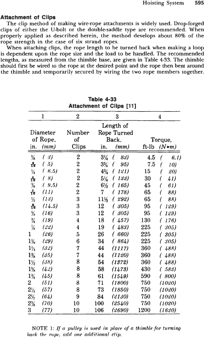
When attaching clips, the rope length to be turned back when making a loop
is dependent upon the rope size and
the
load to be handled. The recommended
lengths, as measured from the thimble base, are given in Table
4-33.
The thimble
should first
be
wired to the rope at the desired point and the rope
then
bent around
the thimble
and
temporarily secured
by
wiring the two rope members together.
Table
4-33
Attachment
of
Clips
[ll]
~ ~~~
Length
of
Diameter
Number
Rope
Turned
of
Rope,
of
Back,
Torque,
in.
(mm)
Clips in.
(mm)
ft-lb
(Nwn)
2
3%
(
8-9)
2
3%.
(
95)
2
4%
(
121)
2
5%
(
133)
2
6%
(
165)
2
7
(
178)
3
11%
(
292)
3
12
(
305)
3
12
(
605)
4
18
(
457)
4
19
(
483)
5
26
(
660)
6
34
(
864)
7
44
(1117)
7
44
(1120)
8
54
(1872)
8
58
(1473)
8
61
(1549)
8
71
(1800)
8
73
(1850)
10
100
(2540)
9
84
(2130)
4.5
(
6.1)
7.5
(
10)
15
(
20)
30
(
41)
45
(
61)
65
(
88)
65
(
88)
95
(
129)
95
(
129)
130
(
176)
225
(
305)
225
(
305)
225
(
$05)
360
(
488)
360
(
488)
360
(
488)
430
(
586)
590
(
800)
750
(1020)
750
(1020)
750
(1020)
750
(1020)
3
(77)
10
106
(2690)
1200
(1630)
NOTE
I:
Ij
u
pulley
in
uxed
in
place
of
a
thimhk
for
turning
buck
the
rope.
udd
one
additional
dip.
596
Drilling and Well Completions
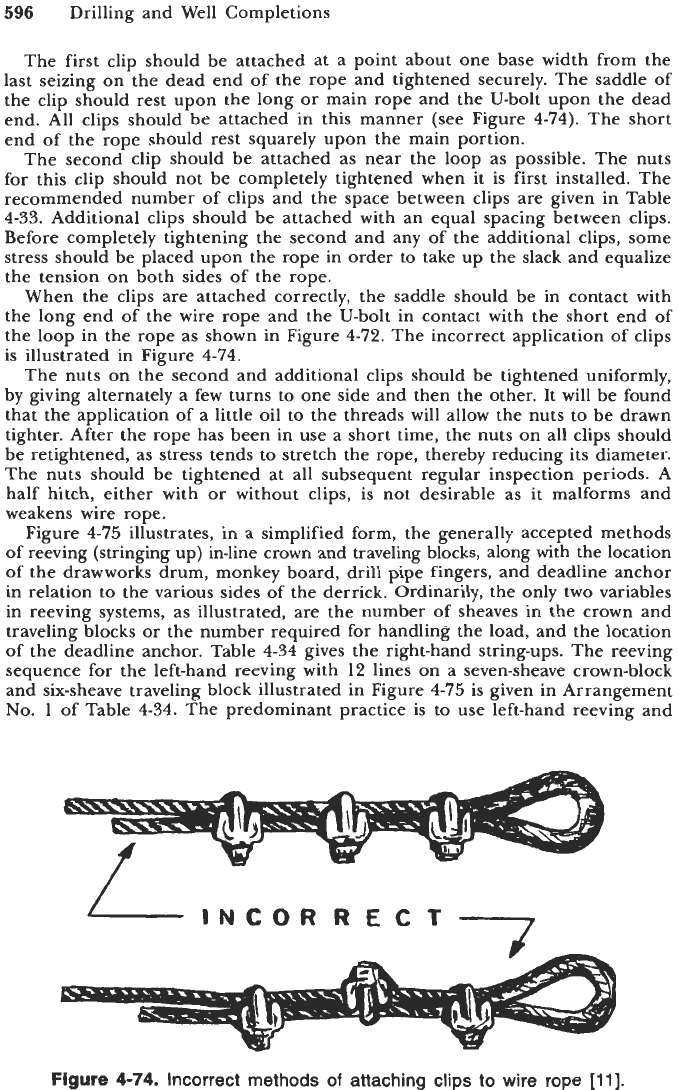
The first clip should be attached at a point about one base width from the
last seizing on the dead end of the rope and tightened securely. The saddle of
the clip should rest upon the long or main rope and the U-bolt upon the dead
end. All clips should be attached in this manner (see Figure
4-74).
The short
end of the rope should rest squarely upon the main portion.
The second clip should be attached as near the loop as possible. The nuts
for this clip should not be completely tightened when it is first installed. The
recommended number of clips and the space between clips
are
given in Table
4-33.
Additional clips should be attached with an equal spacing between clips.
Before completely tightening the second and any of the additional clips, some
stress should be placed upon the rope in order to take up the slack and equalize
the tension on both sides
of
the rope.
When the clips are attached correctly, the saddle should be in contact with
the long end
of
the wire rope and the U-bolt in contact with the short end of
the loop in the rope as shown in Figure
4-72.
The incorrect application of clips
is illustrated in Figure
474.
The nuts on the second and additional clips should be tightened uniformly,
by giving alternately a few turns to one side and then the other. It will be found
that the application of a little oil to the threads will allow the nuts to be drawn
tighter. After the rope has been in use a short time, the nuts on all clips should
be retightened, as stress tends to stretch the rope, thereby reducing its diameter.
The nuts should be tightened at all subsequent regular inspection periods.
A
half hitch, either with or without clips, is not desirable as it malforms and
weakens wire rope.
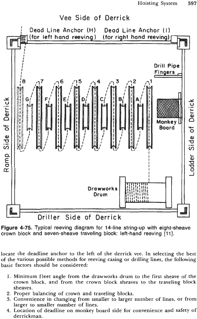
Figure
4-75
illustrates, in a simplified form, the generally accepted methods
of reeving (stringing up) in-line crown and traveling blocks, along with the location
of the drawworks drum, monkey board, drill pipe fingers, and deadline anchor
in relation to the various sides of the derrick. Ordinarily, the only two variables
in reeving systems, as illustrated, are the number of sheaves in the crown and
traveling blocks or the number required for handling the load, and the location
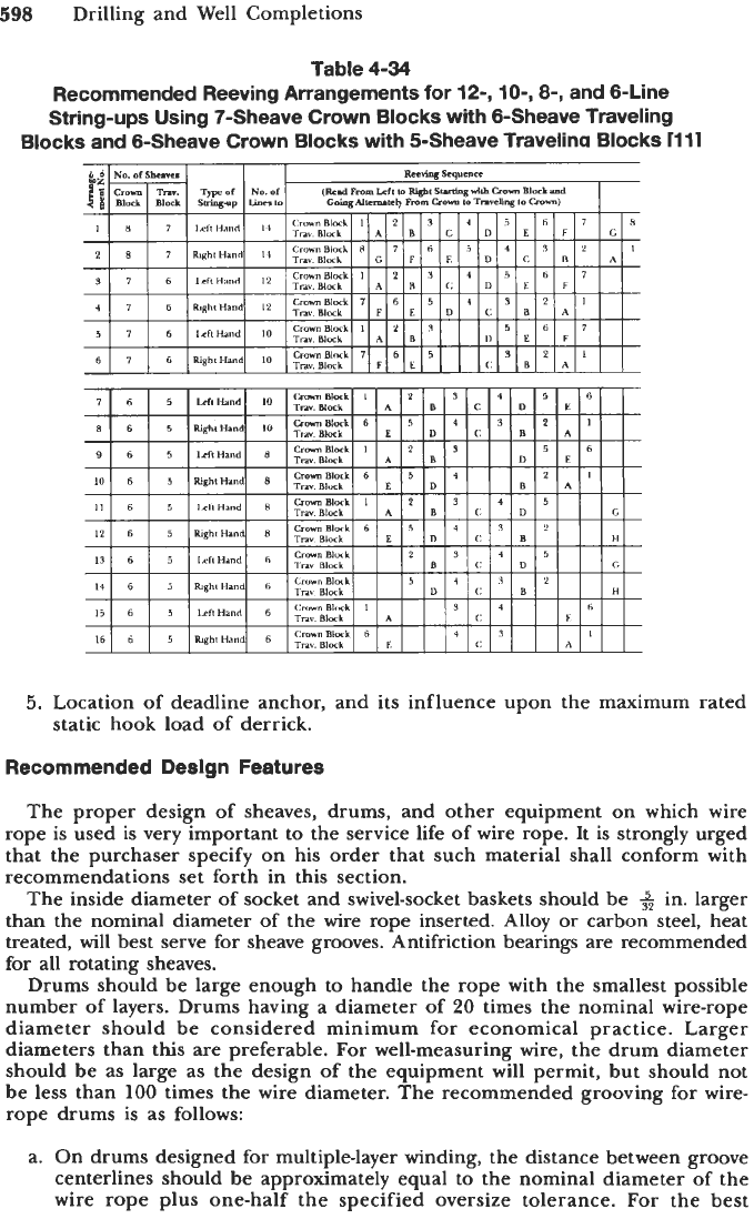
of the deadline anchor. Table
4-34
gives the right-hand string-ups. The reeving
sequence for the left-hand reeving with
12
lines on a seven-sheave crown-block
and six-sheave traveling block illustrated in Figure
4-75
is given in Arrangement
No.
1
of Table
4-34.
The predominant practice is to use left-hand reeving and
-
INCOR
R
EC
T--/
Figure
4-74.
Incorrect methods
of
attaching clips to wire rope
[ll].
Hoisting System
597
Vee
Side
of
Derrick
i
Dead Line Anchor
(HI
Dead Line Anchor
(I)
(for
right hand reeving)
(for left hand
reeving)
I
I
I
I
I
I
I
I
I
Drill Pipe
rinqers
I
I
I
I
I
I
I
n
!
n
Figure
4-75.
Typical reeving diagram for 14-line string-up with eight-sheave
crown
block and seven-sheave traveling block: left-hand reeving
[
111.
locate the deadline anchor to the left of the derrick vee. In selecting the best
of the various possible methods for reeving casing
or
drilling lines, the following
basic factors should be considered:
1.
Minimum fleet angle from the drawworks drum to the first sheave of the
crown block, and from the crown block sheaves to the traveling block
sheaves.
2.
Proper balancing of crown and traveling blocks.
3.
Convenience in changing from smaller to larger number of lines,
or
from
4.
Location of deadline on monkey board side for convenience and safety
of
larger to smaller number of lines.
derrickman.
Y
0
a3
--
L
L
Q
0
aJ
U
v,
aJ
U
U
0
J
rc
.-
L
598
Drilling and Well Completions
Table
4-34
Recommended Reeving Arrangements for
12-,
lo-,
8-,
and 6-Line
String-ups Using 7-Sheave Crown Blocks with &Sheave Traveling
Blocks
and 6-Sheave Crown
Blocks
with 5-Sheave Travelina
Blocks
1111
5.
Location of deadline anchor, and its influence upon the maximum rated
static hook load of derrick.
Recommended Design Features
The proper design
of
sheaves, drums, and other equipment on which wire
rope is used is very important to the service life of wire rope. It
is
strongly urged
that the purchaser specify on his order that such material shall conform with
recommendations set forth in this section.
The inside diameter of socket and swivel-socket baskets should be
+
in. larger
than the nominal diameter of the wire rope inserted. Alloy
or
carbon steel, heat
treated, will best serve for sheave grooves. Antifriction bearings are recommended
for
all rotating sheaves.
Drums should be large enough to handle the rope with the smallest possible
number of layers. Drums having a diameter of
20
times the nominal wire-rope
diameter should be considered minimum for economical practice. Larger
diameters than this are preferable.
For
well-measuring wire, the drum diameter
should be as large as the design of the equipment will permit, but should not
be less than
100
times the wire diameter. The recommended grooving for wire-
rope drums is as follows:
a. On drums designed
for
multiple-layer winding, the distance between groove
centerlines should be approximately equal to the nominal diameter of the
wire rope plus one-half the specified oversize tolerance.
For
the best
Hoisting System
599
spooling condition, this dimension can vary according to the type of
operation.
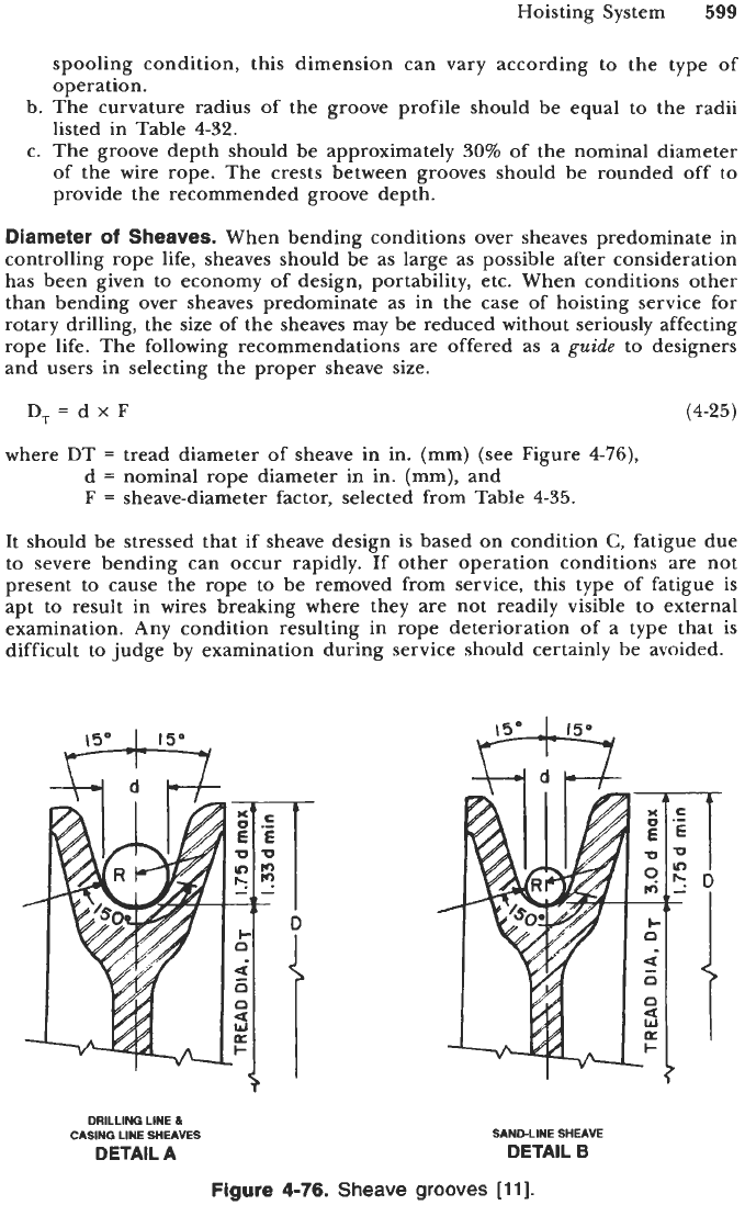
b. The curvature radius of the groove profile should be equal to the radii
listed in Table
4-32.
c. The groove depth should be approximately
30%
of the nominal diameter
of the wire rope. The crests between grooves should be rounded off to
provide the recommended groove depth.
Diameter
of
Sheaves.
When bending conditions over sheaves predominate in
controlling rope life, sheaves should be as large as possible after consideration
has been given to economy of design, portability, etc. When conditions other
than bending over sheaves predominate as in the case of hoisting service for
rotary drilling, the size of the sheaves may be reduced without seriously affecting
rope life. The following recommendations are offered as a
guide
to designers
and users in selecting the proper sheave size.
D,=dxF
(4-25)
where DT
=
tread diameter of sheave in in. (mm) (see Figure
4-76),
d
=
nominal rope diameter in in. (mm), and
F
=
sheave-diameter factor, selected from Table
4-35.
It should be stressed that if sheave design is based on condition
C,
fatigue due
to severe bending can occur rapidly. If other operation conditions are not
present to cause the rope to be removed from service, this type of fatigue is
apt to result in wires breaking where they are not readily visible to external
examination. Any condition resulting in rope deterioration of a type that is
difficult to judge by examination during service should certainly be avoided.
DRILLING
LINE
&
CASING
LINE
WEAVES
SAhIDLfflE
SHEAVE
DETAfL
A
DETAIL
B
Figure
4-76.
Sheave
grooves
[ll].
600
Drilling and Well Completions
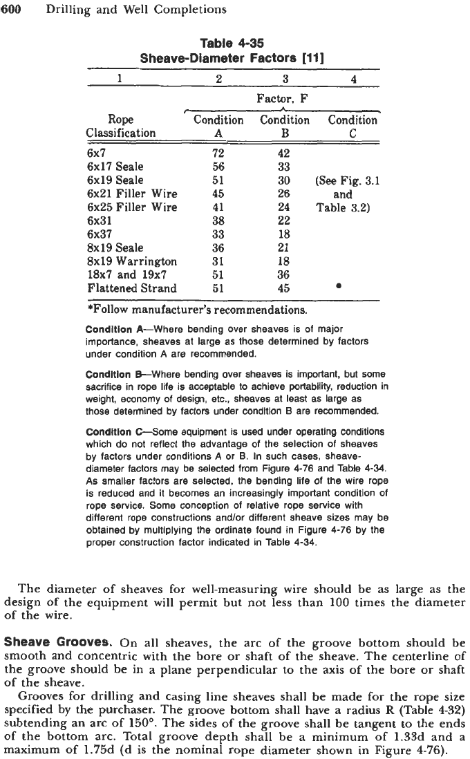
Table
4-35
Sheave-Diameter Factors
[ll]
1
2
3
4
Factor.
F
Rope
Condition Condition Condition
Classification
A
B
C
6x7
72 42
6x17
Seale
56 33
6x19
Seale
51 30
(See
Fig.
3.1
6x21
Filler Wire
45 26
and
6x25
Filler Wire
41 24
Table
3.2)
6x31
38
22
6x37 33 18
8x19
Seale
36 21
8x19
Warrington
31 18
18x7
and
19x7 51 36
Flattened Strand
51
45
*Follow
manufacturer's recommendations.
Condition
A-Where bending over sheaves is of major
importance, sheaves at large as those determined by factors
under condition
A
are recommended.
Condltlon
B-Where bending over sheaves is important, but some
sacrifice in rope life is acceptable to achieve portability, reduction in
weight, economy
of
design, etc., sheaves at least as large as
those determined by factors under condition
B
are recommended.
Condltlon
C-Some equipment is used under operating conditions
which do not reflect the advantage
of
the selection
of
sheaves
by factors under conditions
A
or B. In such cases, sheave-
diameter factors may be selected from Figure
4-76
and Table
4-34.
As
smaller factors are selected, the bending life of the wire rope
is reduced and it becomes an increasingly important condition of
rope service. Some conception of relative rope service with
different rope constructions and/or different sheave sizes may be
obtained by multiplying the ordinate found in Figure
4-76
by the
proper construction factor indicated in Table
4-34.
The diameter of sheaves for well-measuring wire should be as large as the
design
of
the equipment will permit but not less than
100
times the diameter
of
the wire.
Sheave Grooves.
On all sheaves, the arc
of
the groove bottom should be
smooth and concentric with the bore or shaft of the sheave. The centerline of
the groove should be in a plane perpendicular to the
axis
of the bore
or
shaft
of
the sheave.
Grooves for drilling and casing line sheaves shall be made for the rope size
specified by
the
purchaser. The groove bottom shall have a radius
R
(Table
432)
subtending an arc of
150".
The sides of the groove shall be tangent to the ends
of
the bottom arc. Total groove depth shall be a minimum of 1.33d and a
maximum of 1.75d (d is the nominal rope diameter shown in Figure 4-76).
Hoisting System
601
Grooves for sand-line sheaves shall be made for the rope size specified by
the purchaser. The groove bottom shall have a radius
R
(Table 4-32) subtending
an arc of
150'.
The sides of the groove shall be tangent to the ends
of
the
bottom arc. Total groove depth shall be a minimum of 1.75d and a maximum
of 3d (d is nominal rope diameter shown in Figure 4-77B).
Grooves on rollers of oil savers should be made to the same tolerances as
the grooves on the sheaves.
Sheaves conforming to the specifications (Specification
8A)
shall be marked
with the manufacturer's name
or
mark, the sheave groove
size
and the sheave
OD.
These markings shall be cast or stamped on the outer rim of the sheave
groove and stamped on the nameplate
of
crown and traveling blocks. For
example,
a
36-in. sheave with
1
+
in. groove shall be marked
AB
CO
1
1/8
SPEC
8A
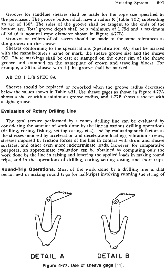
Sheaves should be replaced or reworked when the groove radius decreases
below the values shown in Table 431. Use sheave gages as shown in Figure
4-77A
shows
a
sheave with a minimum groove radius, and 4-77B shows a sheave with
a tight groove.
Evaluation
of
Rotary Drilling Line
The total service performed by a rotary drilling line can be evaluated by
considering the amount
of
work done by the line in various drilling operations
(drilling, coring, fishing, setting casing, etc.), and by evaluating such factors as
the stresses imposed by acceleration and deceleration loadings, vibration stresses,
stresses imposed by friction forces
of
the line in contact with drum and sheave
surfaces, and other even more indeterminate loads. However, for comparative
purposes, an approximate evaluation can be obtained by computing only the
work done by the line in raising and lowering the applied loads in making round
trips, and in the operations of drilling, coring, setting casing, and short trips.
Round-Trip Operations.
Most of the work done by
a
drilling line
is
that
performed in making round trips (or half-trips) involving running the string of
OETAIL
A
DETAIL
B
Figure
4-77.
Use
of
sheave gage
[ll].
602
Drilling and Well Completions
drill pipe into the hole and pulling the string out
of
the hole. The amount of
work performed per round trip should be determined by
D(L,
+
D)W,
+
T,
=
10,560,000 2,640,000
(4-26)
where Tr
=
ton-miles (weight in tons times distance moved in miles)
D
=
depth of hole in feet
Ls
=
length of drill-pipe stand in feet
N
=
number of drill-pipe stands
M
=
total weight of traveling block-elevator assembly in pounds
C
=
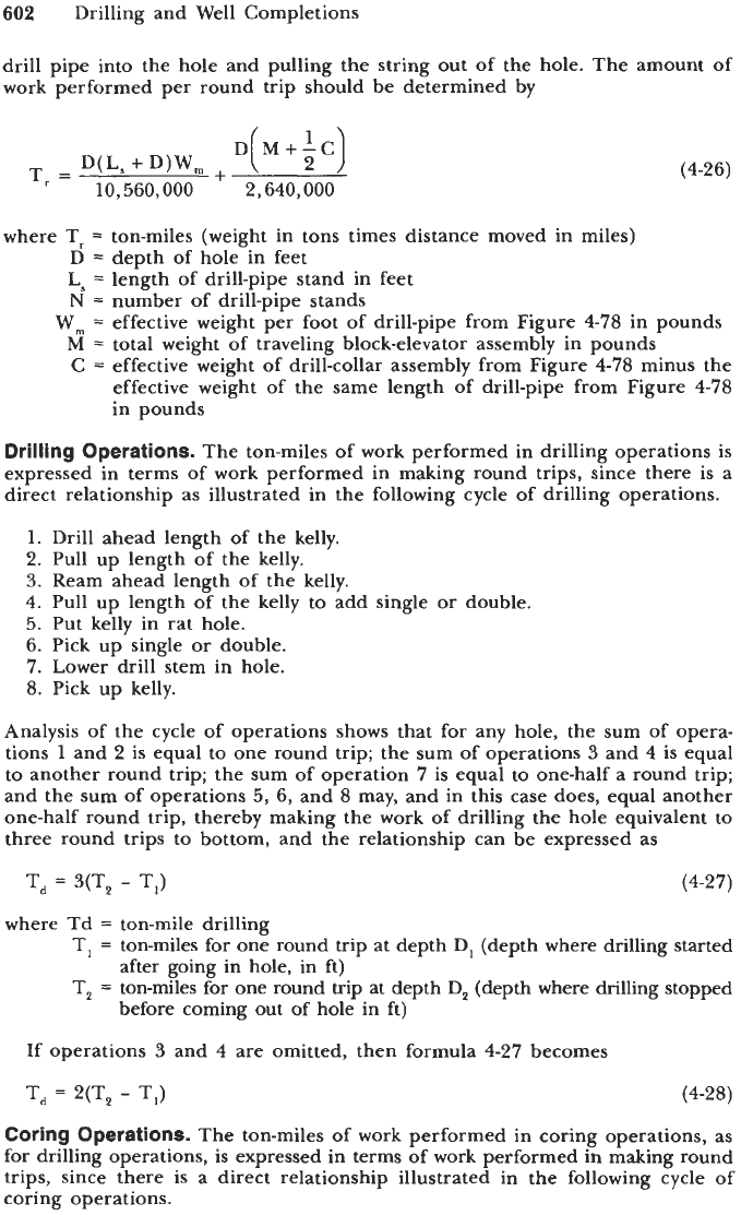
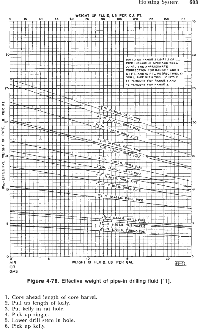
effective weight of drill-collar assembly from Figure
4-78
minus the
effective weight of the same length of drill-pipe from Figure
478
in pounds
Wm
=
effective weight per foot of drill-pipe from Figure
4-78
in pounds
Drilling Operations.
The ton-miles of work performed in drilling operations is
expressed in terms of work performed in making round trips, since there is a
direct relationship
as
illustrated in the following cycle of drilling operations.
1.
Drill ahead length of the kelly.
2.
Pull up length of the kelly.
3.
Ream ahead length of the kelly.
4.
Pull up length of the kelly
to
add
single
or
double.
5.
Put kelly in rat hole.
6.
Pick up single
or
double.
7.
Lower drill stem in hole.
8.
Pick up kelly.
Analysis of the cycle of operations shows that for any hole, the sum of opera-
tions
1
and
2
is equal to one round trip; the sum of operations
3
and
4
is equal
to another round trip; the sum of operation
7
is equal to one-half a round trip;
and the sum of operations
5,
6,
and
8
may, and in this case does, equal another
one-half round trip, thereby making the work of drilling the hole equivalent
to
three round trips to bottom, and the relationship can be expressed as
T,
=
3(T,
-
TI)
(4-27)
where Td
=
ton-mile drilling
T,
=
ton-miles for one round trip at depth
D,
(depth where drilling started
T,
=
ton-miles for one round trip at depth
D,
(depth where drilling stopped
after going in hole, in ft)
before coming out of hole in ft)
If operations
3
and
4
are omitted, then formula
4-27
becomes
T,
2(T,
-
T,)
(4-28)
Coring Operations.
The ton-miles of work performed in coring operations, as
for drilling operations, is expressed in terms of work performed in making round
trips, since there is a direct relationship illustrated in the following cycle of
coring operations.
Hoisting System
603
WEIGHT
OF
FLUID, LB
PER
CU.
FT.
0
I5
30
45
60
75
90
I05
120
135
150
165
35
30
JOINT.
THE
APP
CORRECTION
FO
+OPERCENT
FOR
RANGE
IAN0
25
20
I5
IO
5
0
OR
GAS
WEIGHT OF FLUID, LB
PER
GAL.
Figure
4-78.
Effective weight of pipe-in drilling fluid
[ll].
1.
2.
3.
4.
5.
6.
Core ahead length
of
core barrel.
Pull
up
length
of
kelly.
Put kelly in rat hole.
Pick
up
single.
Lower drill stem in hole.
Pick
up
kelly.
604
Drilling and Well Completions
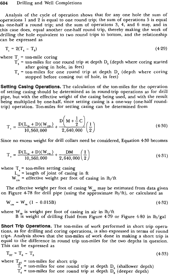
Analysis of the cycle of operation shows that for any one hole the sum of
operations
1
and 2 is equal to one round trip; the sum of operations
5
is equal
to
one-half
a
round trip; and the sum of operations
3,
4,
and
6
may, and in
this case does, equal another one-half round trip, thereby making the work of
drilling the hole equivalent to two round trips to bottom, and the relationship
can be expressed
as
Tc
2(T,
-
T,)
(4-29)
where
Tc
=
ton-mile coring
T,
=
ton-miles for one round trip at depth D, (depth where coring started
T,
=
ton-miles for one round trip at depth D, (depth where coring
Setting Casing Operations.
The calculation of the ton-miles for the operation
of
setting casing should be determined as in round-trip operations as for drill
pipe, but with the effective weight of the casing being used, and with the result
being multiplied by one-half, since setting casing is a one-way (one-half round-
trip) operation. Ton-miles for setting casing can be determined from
after going in hole, in feet)
stopped before coming out of hole, in feet)
T,
=
D(L,
+
DXW,
1
+
10,560,000
(4-30)
Since no excess weight for drill collars need be considered, Equation
430
becomes
D(L,
+
D)(W,
)
+
DM
10,560,000
2,640,000
(i)
T,
=
(4-31)
where TI
=
ton-miles setting casing
L,,
=
length of joint of casing in ft
Wcm
=
effective weight per foot
of
casing in lb/ft
The effective weight per foot of casing Wm may be estimated from data given
on Figure
4-78
for drill pipe (using the approximate Ib/ft),
or
calculated as
Wcm
=
Wca
(1
-
0.015B)
(4-32)
where
Wc.
is weight
per
foot of casing in air
in
Ib/ft
Short
Trip Operations.
The ton-miles of work performed in short trip opera-
tions, as for drilling and coring operations, is also expressed in terms of round
trips. Analysis shows that the ton-miles of work done in making
a
short trip is
equal to the difference in round trip ton-miles for the two depths in question.
This can be expressed
as
B
is weight of drilling fluid from Figure
4-79
or
Figure
4-80
in lb/gal
T,
=
T,
-
T5
where
TsT
=
ton-miles for short trip
T,
=
ton-miles for one round trip at depth
D,
(shallower depth)
T,
=
ton-miles for one round trip
at
depth
D,
(deeper depth)
(4-33)