Malcolm Barnes. Practical Variable Speed Drives and Power Electronics
Подождите немного. Документ загружается.

Electromagnetic compatibility (EMC) 139
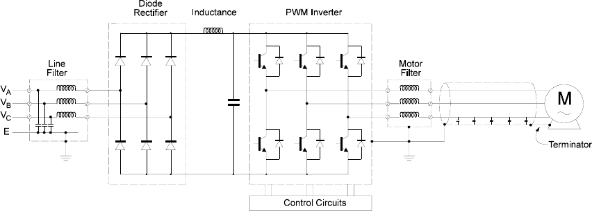
Figure 4.15:
An AC drive fitted with line-side and motor-side filters

5
Protection of AC converters and
motors
5.1 Introduction
The protection of AC variable speed drives includes the protection of the following two
major components of a VSD:
• The AC converter
• The electric motor
In modern digital AC variable speed drives, most of the protection functions are
implemented electronically within the control system of the AC converter. However, to
be effective, external sensors are necessary to monitor either the current or the
temperature directly. The temperature rise in a motor and converter is the main cause of
damage. Since temperature rise is usually the result of high current flow, the sensing of
current is a common method of implementing overload and short circuit protection.
5.2 AC frequency converter protection circuits
Digital AC frequency converters usually include a considerable number of protection
features to protect the AC converter itself, the output cable and the motor. However, the
protection built into the AC converter control system does NOT protect the input side of
the converter, which comprises the power supply cable and the rectifier. Short circuit and
earth-fault protection must be provided upstream in the main distribution board (DB) or
motor control center (MCC). Suitable protection can be provided by:
• Moulded case circuit breakers (MCCB)
• To provide adequate speed, these need to be of the current limiting type
• High rupturing capacity (HRC) fuses
Protection of AC converters and motors 141
• The fuses are often provided as part of the main isolating switch, which is
usually provided for safety isolation. The types of fuses depend on the length
of the power supply cable and the inductance of this path.
On the output side, a modern well designed VSD will protect itself from almost all the
common faults on the motor side of the converter, such as short-circuit, earth fault,
thermal overload, etc. VSDs also usually provide thermal overload protection for the
motor.
One of the few faults that will cause damage to the converter is the inadvertent
connection of the mains supply to the motor terminals. The inrush through the reverse
connected diodes in the inverter will result in inverter damage.
The following protection features are usually available in most modern digital AC
converters. These overall protection features are also summarized in Figure 5.3.
• AC input under-voltage protection
• DC bus under-voltage protection
• AC input over-voltage protection
• DC bus over-voltage protection
• Output over-current (short-circuit) protection
• Output earth-fault protection
• Heat-sink over-temperature protection
• Motor thermal over-load protection
5.2.1 AC and DC under-voltage protection
The under-voltage protection system monitors the voltage on the 3 incoming phases as
well as the DC bus voltage and responds to various faults as outlined below.
If the supply voltage falls to a low level as a result of some upstream power system
fault, it is unlikely that the converter will be damaged. The input diode rectifier of a
PWM converter can safely operate at any voltage between zero and the over-voltage trip
point. So, a power supply under-voltage event is not really a problem for the power
circuit.
Under-voltage protection is mainly required to ensure that all the various power
supplies are operating within their required specification. If a power supply unit should
lose output voltage regulation, the following could occur:
• The DC bus charging relays may drop out
• The microprocessor could switch to an indeterminate state
• The driver circuits for the main power switches will lose sufficient voltage
and current to ensure proper turn-on or turn-off of the switching device
• If there is insufficient turn-on current, a power device may come out of
saturation, and attempt to operate in the linear region and losses will increase
• If there is insufficient reverse bias, the power device will be slow to switch off
or not switch off at all. Either way, the power electronic switches will fail
Under-voltage protection can be implemented in a number of ways within a VSD:
• Loss of AC supply voltage
Loss of AC power can be detected by monitoring the three AC line voltages
and comparing these to a preset trip point. AC supply under-voltages can be
142 Practical Variable Speed Drives and Power Electronics
caused by a complete loss of supply or alternatively a voltage sag (dip) of
short duration.
Since the power supply for the converter control circuits is taken from the DC
bus via a switch mode power supply (SMPS), it is not necessary to stop the
converter immediately the supply voltage is lost. If required, the converter can
continue to operate, initially taking energy from the large capacitor on the DC
bus. As the DC bus voltage starts to fall, the output frequency can be reduced
to allow the motor to behave as an induction generator, driven by the inertia
of the mechanical load. This situation could be maintained for a period until
the motor stops turning.
Alternatively, the control circuit can be programmed to trip immediately the
AC supply voltage is lost. The selection to trip (or not to trip) on loss of AC
supply can usually be made by changing a bit in the control logic.
• Loss of DC bus voltage
The DC voltage can be monitored by a comparator circuit (hardware or
software) that compares the DC bus voltage to a preset minimum voltage
level. When the DC bus voltage falls below this level, the converter may be
shut down (tripped). This trip level is typically set at the lowest rated input
voltage, minus 15%. For example, if the VSD is rated at 380 V–460 V ±10%,
the lowest specified operating level would be 342 V AC, with an equivalent
DC voltage of 485 V DC. The DC bus trip point would typically be set at
485 V DC –15%, that would be 411 V DC.
In addition to this main DC bus trip point, some of the individual modules
sometimes shut down independently. For example, each driver module may
have its own under-voltage sensing circuit to ensure that sufficient base or
gate drive voltage is available before switching. If these trip, a signal would
be returned to the main processor indicating local device failure. These local
under-voltage trips are usually used only on critical modules, such as
transistor driver circuits.
5.2.2 AC and DC bus over-voltage protection
Ultimately all the electrical components will fail if exposed to a sufficiently high over-
voltage. In an AC variable speed drive, over-voltages can occur for the following reasons
• High voltages in the mains power supply
• High voltages generated by the connected motor behaving as an induction
generator when trying to reduce the speed of a high inertia load (braking) too
quickly
In an AC converter, the DC bus capacitor bank, the DC bus connected power supply
module and the main power electronic switching devices have the lowest tolerance to
high voltages.
The capacitor bank usually consists of individual capacitors in series and parallel.
When capacitors are connected in series, the voltage sharing will not be perfect, and so
the maximum voltage will be less than the sum of the individual ratings.
Protection of AC converters and motors 143
For example, if two 400 Vdc capacitors are connected in series, the nominal rating
would be 800 V DC. However, the actual safe operating voltage may only be 750 V DC,
due to the unequal voltage sharing characteristics. This value will be a function of the
capacitor leakage current and the value of the sharing resistor in parallel with each
capacitor. The lower the value of the sharing resistor, the better the sharing will be but
this will also increase drive losses.
The peak voltage on the DC bus is √2 (1.414) times the mains phase voltage. If the
maximum rated capacitor voltage is 750 V DC, and allowing for a plus 10% variation in
the mains voltage, the practical limit for input voltage is 480 V AC.
The power semiconductor switching devices, in the rectifier and inverter, are usually
rated at maximum voltage of 1200 V DC. Although this seems well above the maximum
capacitor rating, the voltage across a device during turn-off will be much higher than the
DC bus voltage, particularly during fault conditions. This is due to stray inductances in
the circuit. These voltage peaks can reach about 400 V, so the bus voltage prior to the
fault must usually be limited to around 800 V DC maximum, depending on the drive
design and the rating of the power devices.
In analog converters, the over-voltage protection is usually a hardware protection
system through a simple comparator circuit operating with a fixed set point.
In modern digital converters, the over-voltage protection is usually provided by the
microprocessor. This is possible because the DC bus voltage changes relatively slowly,
due to the filtering effect of the capacitors.
In microprocessor controlled VSDs, the processor can also provide some over-voltage
control. Most DC bus over-voltages are caused by incorrect setting of the deceleration
(ramp-down) times of high inertia motor loads. If the deceleration time is set too low
compared to the natural run-down time of a rotating load, the motor will behave like an
induction generator and power will be transferred from the motor to the DC bus. The DC
bus voltage could rise until the over-voltage trip level is reached. Many VSDs have a
selectable feature whereby the controller will override the set deceleration time and
prevent the over-voltage trip. The DC bus voltage is allowed to rise to a ‘safe’ high
voltage, typically 750 V DC, and rate of deceleration is controlled to keep the voltage
below the trip level of 800 V DC.
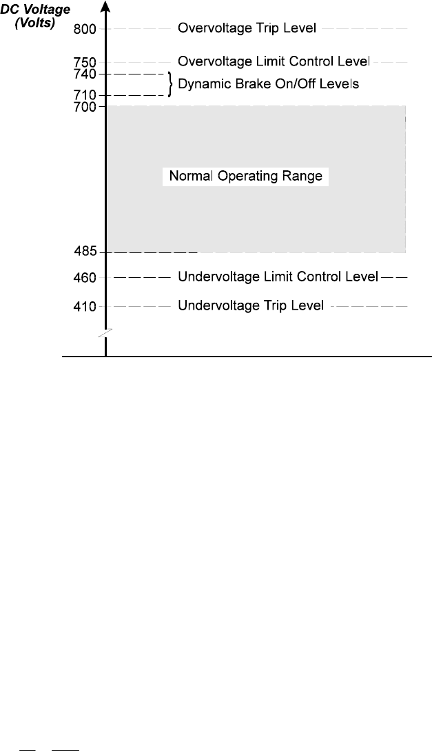
The under- and over-voltage protection is normally monitored at the DC bus because
this is the source of DC power for both the inverter and the control circuits. Typical
operating regions and the protection trip levels are summarized in Figure 5.1.
144 Practical Variable Speed Drives and Power Electronics
Figure 5.1:
Typical DC bus under- and over-voltage protection levels
5.2.3 Output over-current protection
The purpose of over-current protection is to avoid failure of the main power
semiconductors (IGBTs, BJTs, MOSFETs, GTOs, etc) during phase-to-phase short
circuits on the motor side of the converter. Unlike diodes and SCRs, fuses are not
appropriate for the protection of most power switches due to their I
2
t characteristics.
The most effective method of protection is to switch all the inverter switching devices
off when the current rises above a given set point. The protection level is dependent on
their safe operating area characteristic. This maximum fault current is usually what
determines the maximum rating of the drive. Typically, the trip current is around 200% of
the drive current rating, with current limiting at 150% or sometimes 180%.
To maximize the effective rating of the VSD, it may be possible to operate closer to the
trip current if the rate of rise (di/dt) of current is controlled. This can be achieved by
introducing a choke between the power semiconductor device and the output terminals of
the VSD. If a short circuit occurs on the VSD output, the rate of change of current (di/dt)
will be equal to the bus voltage divided by the inductance:
L
V
=
t
i
out
bus
d
d
For example, with a 600 V DC bus voltage and a 100 µH output choke, the current rise
time will be limited to 6 amp/µsec. For a short circuit on the output of a 50 kW AC
converter, with a trip current level of 200 amp, it will take 33.3 µsec to reach the trip
point.
Protection of AC converters and motors 145
This is significant when considering the propagation delay through the current
feedback and protection circuits. The propagation delay is the amount of time between
the actual current reaching the trip point and the turn off of the power devices. This delay
exists in the current measuring device, the amplifiers through which the signal passes, the
comparator itself, the power device driver circuit and the actual power device.
If the propagation delay and the rate of change of current are known, then the actual
device current when the power devices switch off can be estimated. For example, if the
total propagation delay is 3 µsec and the di/dt is 6 amp/µS, then the actual device current
will be 18 amps higher than the current trip point when the devices actually turn off. This
is called current overshoot.
While larger output chokes will reduce this overshoot and have a few other advantages,
they also introduce losses, are bulky and expensive. For this reason it is important to
minimize the propagation delay in the over-current protection circuit. As a result, high
bandwidth current feedback and amplifiers are usually used. To minimize propagation
delays in the microprocessor, it is common for over-current protection to be performed
completely in hardware, even in a digital VSD.
Over-current events can also occur as a result of sudden increases in the load torque on
the motor or during periods of high motor acceleration. These increases in current occur
relatively slowly, allowing the current to be monitored and controlled by the
microprocessor. The increase in current can be limited to a preset value typically of up to
150% of the rated converter current. The current limit control system regulates the output
frequency in such a way that it reduces the motor torque. If the over-current is due to a
high rate of acceleration, current is reduced by reducing the rate of increase of current. If
the over-current is due to a temporary motor overload, the output speed may be reduced.
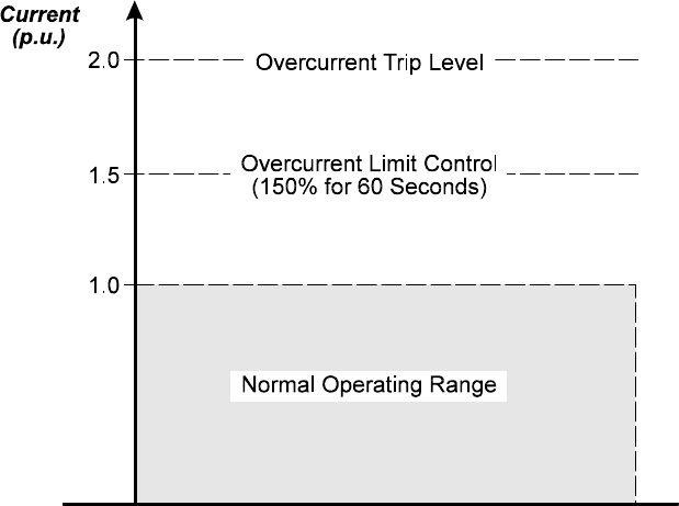
Typical over-current protection and current limit levels are summarized in Figure 5.2.
Figure 5.2:
Typical over-current protection levels and current limit settings

146 Practical Variable Speed Drives and Power Electronics
5.2.4 Output earth fault protection
Earth fault protection is designed to detect a short circuit between a phase and earth, on
the output side of the VSD, and immediately shuts down the converter. This protection is
generally not intended for protection of human life from electric shock, as the trip points
are set much higher than acceptable human safety limits. This feature is mainly for the
protection of the AC converter itself.
Figure 5.3:
Core balance current transformer for earth fault protection. The normal operating condition, no earth fault
present
Earth fault protection is usually implemented by means of a core balance current
transformer. This is constructed from a toroidal magnetic core through which either the
DC bus cables or the output motor phase cables are passed. A low current secondary
winding is wound around the toroid and connected to the protection circuit. If the vector
sum of all the currents passing through the core add up to zero, the flux in the core will be
zero. A net zero flux is the normal operating situation.
If an earth fault occurs and there is a path for current to earth, the sum of the currents
through the core balance transformer will no longer be zero and there will be a flux in the
core as shown in Figure 5.4.
Figure 5.4:
Core balance current transformer for earth fault protection. Earth fault condition, the net current is not equal
to zero
Protection of AC converters and motors 147
This flux will result in a current being generated in the secondary protection winding,
which is converted to a voltage via a burden resistor. A comparator circuit detects the
fault and shuts down all the power device drives. Typically, the protection trip level is
around 5 amp.
Care must be taken in establishing the set point for the earth fault trip circuit. In all
PWM VSDs, some leakage current will always take place to earth due to the high
frequency components of the motor current waveform and the capacitance of the motor
cables to earth. High leakage currents can sometimes cause some nuisance tripping of the
earth fault protection.
5.2.5 Heat-sink over-temperature protection
Over-temperature protection is usually provided to prevent over heating of various
components in the converter, particularly the junction temperature of the power
semiconductors, which is limited to 150
o
C. To ensure this limit is not reached, the heat-
sink temperatures are usually maintained at temperatures below 80
o
C to 90
o
C, depending
on the actual design. Consequently most heat-sinks are fitted with temperature sensors or
switches to detect when the maximum temperatures are reached.
Other modules, such as the power supplies or device driver modules, may have their
own individual over-temperature protection. It is common to measure ambient air
temperature close to the control electronics to ensure this does not exceed device ratings
(usually ±70
o
C).
Low cost drives may rely on simple bimetallic temperature switches (microtherms),
which operate at a specific temperature. However, most modern drives use silicon
junction temperature sensors to feed back the actual temperature to the microprocessor.
Using this method, the processor can provide a warning to the operator prior to actual
shutdown. On more advanced VSDs, some corrective action might be taken
automatically, such as reducing the motor speed or reducing the PWM switching
frequency.
5.2.6 Motor thermal overload protection
Almost all modern VSDs include some provision for motor thermal overload protection.
The simplest form of protection is to make provision for a digital input, which shuts
down the drive when some external device, such as a thermal overload or thermistor relay
is activated. Many manufacturers of VSD now make provision for a direct input from a
thermistor sensor, so that only the thermistors need be placed in the motor windings and
eliminates the need for a thermistor relay. The inputs are normally delivered with a
resistor connected across the terminals, which should be removed during commissioning.
This often creates some difficulties during commissioning for those who do not read the
installation manuals.
The most common method used for motor thermal overload protection on digital VSDs
is to use the
current sensing method
with a motor protection model as part of the
microprocessor control program. The measurement of motor current is necessary for
other purposes, so it is a small step to provide motor thermal modeling. The model can
continuously estimate the thermal conditions in the motor and shuts down the VSD if
limits are exceeded.
The simplest motor model is to simulate a eutectic thermal overload relay by integrating
motor current over time. This simplistic method does not provide good motor protection
because the cooling and heating time constants of the motor change at different speeds.
148 Practical Variable Speed Drives and Power Electronics
Over a period of time, the motor protection features in VSDs have become more
sophisticated by using motor frequency as an input so that shaft fan cooling performance,
at various speeds, can also be modeled. The most advanced VSDs require motor
parameters such as rated speed, current, voltage, power factor and power to be entered to
enable a comprehensive motor thermal model to be implemented in software, affording
excellent motor protection without any direct temperature measurement devices.
For these motor models to be accurate and effective, previous conditions need to be
stored in a non-volatile memory in case the power is interrupted. This can be achieved
through simple devices such as capacitors or non-volatile memory chips, such as
EEPROMs and NVPROMs.
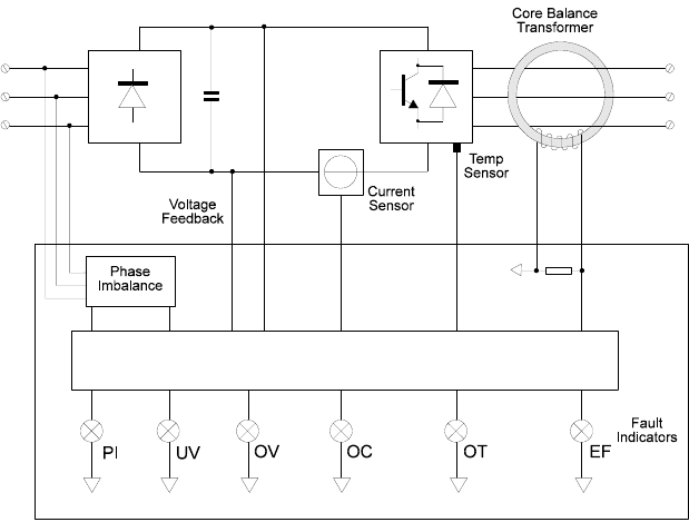
5.2.7 Overall protection and diagnostics
The following block diagram is a summary of the protection features commonly used in
modern digital PWM AC converters. As outlined above, many of these protection
functions are implemented in software, using suitable algorithms. The main exceptions
are the over-current protection and the earth fault protection, which are implemented in
hardware to ensure that they be sufficiently fast to adequately protect the power
semiconductor devices.
Figure 5.5:
Example of VSD protection block diagram
5.3 Operator information and fault diagnostics
Modern digital variable speed drives (VSDs) all have some form of operator interface
module which provides access to internal data about control and status parameters during
normal operation and diagnostic information during fault conditions. This module is
sometimes called the human interface module (HIM), or something similar. The HIM
usually provides an LED or LCD display and some buttons to interrogate the control