Malcolm Barnes. Practical Variable Speed Drives and Power Electronics
Подождите немного. Документ загружается.


Protection of AC converters and motors 149
circuit. This operator interface can also be used to install and change VSD settings
parameters.
In addition, modern VSDs also permit the transfer of these parameters to remote
locations via serial digital data communications. Some details about the serial
communication are covered in the section on installation in Chapter 8. The
communications interface permits control from a remote programmable logic controller
(PLC) as part of an overall automated control system. The diagnostic information can be
transferred over the serial interface to a central control center so that an operator can take
full advantage of the information available.
When an internal or external fault occurs, the control circuit registers the type of fault,
which helps to identify the cause of the fault and the subsequent rectification of the
problem. Modern microprocessor controlled converters employ a diagnostic system that
monitors both the internal and external operating conditions and responds to any faults in
the way programmed by the user. The control system retains the fault information in a
non-volatile memory for later analysis of the events that occurred. This feature is known
as fault diagnostics.
There are three main levels of operator information and fault diagnostics:
• The
first level
provides information about the on-going situation inside a
VSD and refers mainly to the setting parameters and the real-time operating
parameters and metering information, such as output voltage, output current,
output frequency, etc.
• The
second level
provides diagnostic information about the status of the
protection circuits and will indicate the external faults as described above.
• The
third level
provides diagnostic information about the status of internal
faults, such as the identification of failed modules. Dedicated internal
diagnostics are usually only found in high performance VSDs.
The following is a brief list of typical internal parameters and fault conditions.
Module Parameters and fault diagnostics
Power supply Power supply voltage, current and frequency
DC bus DC link voltage and current
Motor Output voltage, current, frequency, speed, torque, temperature
Control signals Setpoint, process variable, error, ramp times
Status Protection circuits, module failures, internal temps, fans running,
switching frequency, current limit, motor protection, etc
Fault conditions Power device fault, power supply failed, driver circuit failed, current
feedback failed, voltage feedback failed, main controller failed
Figure 5.6:
Typical list of variable speed drive parameters
At the
first level
, most modern digital VSDs provide information about the status of:
• All setting parameters which define the operating conditions
• The digital inputs and outputs, such as start, stop, enabled, jog,
forward/reverse, etc
• The status of analog inputs, such as speed reference, torque reference, etc

150 Practical Variable Speed Drives and Power Electronics
• The real-time operating parameters, which include a vast array of information,
such as output frequency, output voltage, output current, etc
At the
second level
, when a fault occurs and the VSD stops, diagnostic information is
provided to assist in the rectification of the fault, thereby reducing downtime. There is
always some overlap between these levels of diagnostics. For example a persistent over-
current trip with no motor connected can indicate a failed power electronic switching
device inside the converter.
The table in Figure 5.7 shows the most common external fault indications provided by
the VSD diagnostics system and the possible internal or external problems that may have
caused them.
Protection Internal Fault External Fault
Over-voltage Deceleration rate set too fast Mains voltage too high transient
over-voltage spike
Under-voltage Internal power supply failed Mains voltage too low Voltage
sag present
Over-current Power electronic switch failed
driver circuit failed
Short circuit in motor or cable
Thermal overload Control circuit failed Motor over-loaded or stalled
Earth fault Internal earth fault Earth fault in motor or cable
Over-temperature Cooling fan failed heat-sink
blocked
Ambient too high enclosure
cooling blocked
Thermistor trip Motor thermistor protection
Figure 5.7:
Variable speed drive diagnostics table
The internal diagnostics system can provide an operator with information about faults
that have occurred inside the drive. This can be further broken down into fault conditions,
such as a failed output device, commutation failures, etc. Fault conditions are indications
that a particular module or device has failed or is not operating normally. To provide fault
condition monitoring, the drive must be specifically designed to include internal fault
diagnostic circuits.
For example, power semiconductor drivers may include circuits that measure the
saturation voltage, which is the voltage across the device when it is on, for each power
semiconductor. This can identify a short circuit in the power switch and the VSD can be
shut down before the external over-current trip or fuses can operate.
Considerable cost and effort is required to implement internal fault condition
monitoring, and only a few high performance VSDs provide extensive internal
diagnostics. This feature can be very useful for trouble-shooting, but this is usually only
warranted when down time represents a major cost to the user.
5.4 Electric motor protection
The useful life of an electric motor is dependent on the following main components:
•
Electrical parts
, such as the stator windings & insulation, the rotor windings
& insulation and their respective external connections
Protection of AC converters and motors 151
•
Mechanical parts
, such as the stator core with slots, the rotor core with slots,
the shaft, the bearings, the frame & end shields and the cooling system.
Using modern materials, most of these components can be designed and constructed to
have a high level of reliability. Experience has shown that mechanical failure is rare and
the most likely causes of failure are:
• Motor overloading, current exceeds rated level for a period of time
• Frequent starting, inching, jogging & reverse plugging, high currents
• Single phasing or unbalanced power supply, high currents
• Stalling, high currents
• High ambient temperature
• Loss of cooling
During the above abnormal operating conditions, the temperatures in the stator and/or
the rotor windings can rise to excessive levels, which causes the degradation of the
insulation materials used to isolate the windings from each other and the earthed frame of
the motor.
The temperature rise in a motor winding is mainly due to the I
2
R losses, or copper
losses, where the heat is generated by the load current (I) flowing through the resistance
(R) of the stator windings. During design, the cross-sectional area of the stator windings
is selected with a particular maximum load current in mind. The design objective is to
balance the I
2
R losses, at maximum rated load, with adequate ventilation or cooling so
that the resulting temperature rise in the winding will be below the critical temperature of
the insulation materials chosen. In AC motors, the stator current is proportional to the
mechanical load torque. In DC motors, the armature current is proportional to the
mechanical load torque. Consequently, each standard motor size is rated for a maximum
stator or armature current.
Excessive winding temperature most commonly occurs when the load current exceeds
the maximum rated value. This condition is called thermal overloading.
When the temperature in a winding rises above a certain critical level, the insulation is
permanently damaged. The critical temperature, above which permanent damage takes
place, is dependent on the type of insulation material used. In the standards, the different
types of insulation are classified into Classes, such as Class-B, Class-F, Class-H, etc.
For example, the temperature in a winding with Class-F insulation is permitted to safely
rise to a maximum of 140
o
C, or 100
o
C above the commonly specified maximum ambient
temperature of 40
o
C, without permanent damage to the insulation.
If the working temperature of the winding increases above 140
o
C, the characteristics of
the insulation material start to degrade. Above 155
o
C, the insulation will be permanently
damaged and its useful life sharply reduced. Insulation failure results in short circuits or
earth faults, which would require the replacement or repair of the faulted winding. Long
insulation life is particularly important for electric motors, which operate in strategic
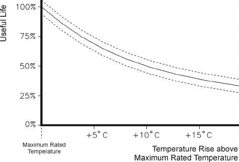
locations in industry under continuously changing load conditions. A constantly applied
temperature rise of just 10
o
C above the maximum rated temperature can reduce the useful
life of a motor to 50% of its original value, as illustrated in the curve below.
152 Practical Variable Speed Drives and Power Electronics
Figure 5.8:
The effect of temperature rise above maximum rated temperature on the useful life of an electric motor
To protect a motor from insulation damage due to excessive temperatures, any
potentially damaging operating condition should be detected by a sensing device and the
motor should be disconnected from the power supply before insulation damage can occur.
The most common devices used for the protection of electric motors are:
•
Current sensing devices
, such as thermal overload protection relays, which
continuously monitor the primary current flowing into the motor windings and
initiate a trip when a preset current level is exceeded.
•
Direct temperature sensing devices
, such as thermostats, thermistors,
thermocouples and RTDs, which continuously monitor the actual temperature
in the motor windings and initiate a trip when a preset temperature level is
exceeded.
5.5 Thermal overload protection – current sensors
Current sensing thermal overload (TOL) protection relays, whether of the indirectly
heated bimetallic type or the electronic type, monitor the stator current in AC motors or
armature current in DC motors, and use this information to determine if the motor has
become over-loaded. TOL relays should be designed to match the thermal characteristics
of the motor.
On smaller motors, a bimetallic type of TOL relay is normally mounted in conjunction
with the motor contactor, which opens when an overload condition is detected. Additional
features usually include phase failure (single phasing) detection. The main advantage of
the bimetallic TOL relay is its low cost and simplicity.
Bimetallic TOL relays do not provide adequate protection for repeated starting, jogging
and other periodic duties. The reason is that the heating and cooling time-constant of the
bimetal are equal, whereas the cooling time-constant of a typical squirrel cage motor is
approximately twice its heating time-constant, mainly because the cooling fan stops when
the motor is stationary. During repeated starting and jogging, the bimetal cools down
faster than the motor and, consequently, does not provide adequate thermal protection.
For larger motors and those with an intermittent duty, it is necessary to use an
electronic motor protection relay, whose thermal characteristics and settings are designed
to more closely match those of the motor. In this case, overload protection is usually part
of an overall motor protection relay, which also provides protection against short circuits,
Protection of AC converters and motors 153
earth faults, stalling, single phasing, multiple starts, etc. Several adjustable settings enable
the motor protection relay to be matched to the type, size and application of the motor.
Modern microprocessor relays can also store and display data such as line currents,
unbalance currents, thermal capacity of the motor, etc, and transfer this information to a
remote host computer over a serial communications link.
Although current sensing TOL protection devices, which monitor stator or armature
current, are cost effective and have a reasonably good response time, they seldom take
into account other environmental conditions, such as reduced cooling, restricted or total
loss of ventilation or excessively high ambient temperatures. For example, in AC variable
speed drives, the shaft mounted fan cooling on a standard AC motor is reduced as the
motor speed is reduced, which changes the heating time constant of the motor when it is
running at speeds below 50 Hz. Most modern digital AC converters have built-in thermal
overload protection, which is designed to compensate for the changes in the heating and
cooling time constants as the speed is adjusted. But, monitoring the stator current is not
always a reliable method for protecting the motor winding insulation from damage due to
over-temperature.
5.6 Thermal overload protection – direct temperature sensing
For the more difficult applications, direct temperature sensing of the winding temperature
at hot spots or other strategic points is preferable. There are several types of devices that
can be used for direct temperature sensing. Some of the most common techniques are
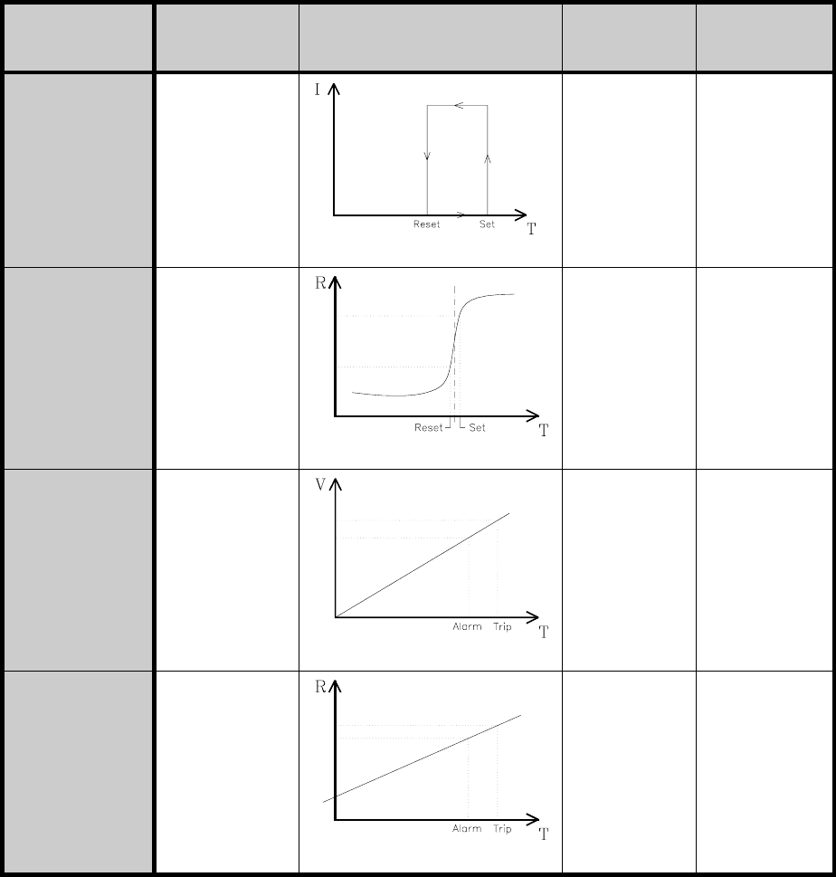
summarized in the table in Figure 5.9.
The following are some of the applications where
direct temperature sensing
is
considered to be more reliable than stator or armature
current sensing
:
• AC squirrel cage induction motors supplied from AC frequency converters
• AC motors which have frequent transient overloads
• AC motors which are frequently stopped or started
• AC motors in high inertia applications with long starting times
• AC motors in applications where the rotor can lock or stall
• DC motors controlled from DC converters
• Thermal protection in mechanical applications, such as large bearings, gear
housings, oil baths, heat sinks, etc
154 Practical Variable Speed Drives and Power Electronics
Type Operating
Principle
Operating
Curve
Protection
Provided
Number
Required
Microtherm
(Thermostat)
Bimetallic strip
with contacts
normally open
or normally
closed
Temperature
monitoring for
non-transient
overloads
2 or 3
connected
in parallel for
N/O in series
for N/C
Positive
temperature
coefficient
thermistor
Variable non-
linear
resistance
of thermistor
sensor
Temperature
monitoring for
transient
overloads
2 or 3
connected in
series
Thermocouple
Peltier effect J-
type (T <
750
o
C)
K-type (T <
1250
o
C) T-type
(T < 350
o
C)
Continuous
temperature
monitoring at
hot spots
1 per hot spot
RTD
resistance
temperature
detector
Variable linear
resistance of
platinum
sensor
Pt-100Ω
High
accuracy
continuous
temperature
monitoring at
hot spots
1 per hot spot
Figure 5.9:
Protection devices used for direct temperature measurement
In practical applications, one or more direct measuring thermal sensors are usually used
to monitor the temperature at several strategic points in an electric motor. These sensors
are used in conjunction with an associated relay or controller, which is connected in the
motor control circuit to provide the following:
Protection of AC converters and motors 155
•
Alarm
: Draws the attention of the operator to the high temperature condition,
using audible and/or visual alarms, without tripping the motor
•
Trip
: Stops the motor by tripping the power supply circuit to the motor
To achieve the objectives of separate alarm and trip setpoints, microtherms and
thermistors require a group of two sensors at each strategic point. The first, with a lower
temperature setpoint, is used to provide the alarm function and the second, with a higher
temperature setpoint, is used to provide a trip function.
With thermocouples and RTDs, which can continuously measure the actual temperature
at each strategic point, the electronic controller normally has two preset temperature
levels for alarm and trip. Two separate contact outputs can then be used to initiate and
alarm or trip the motor.
A detailed description of the various direct temperature sensing methods of motor
protection is given in Appendix A: Motor protection – direct temperature sensing.
6
)UTZXURY_YZKSYLUX')\GXOGHRK
YVKKJJXO\KY
:NKU\KXGRRIUTZXURY_YZKS
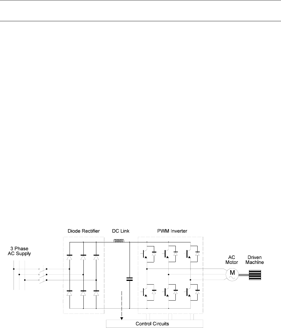
Most modern AC variable speed drives (VSDs) are of modular construction. Some of the
technical details of the main components, such as the input rectifier, DC link, output
inverter and the connected motor have already been covered in the previous chapters.
This chapter covers the control system, embodied in the control circuits.
Figure 6.1:
Main components of an AC variable speed drive
Although the main function of the control system for modern PWM-type AC VVVF
converters is to control the semiconductor switches of the PWM inverter, there are a

Control systems for AC variable speed drives 157
number of other important functions, which need to be controlled. The overall control
system can be divided into 4 main areas:
• Inverter control system
• Speed feedback and control system
• Current feedback and control system
• External interface, which includes the following:
− Parameter settings by the user
− Operator information and fault diagnostics
− Digital and analog inputs to receive control signals (start, stop, etc)
− Digital and analog outputs to pass on status information (running,
faulted, etc)
With the rapid advances is digital electronics over the last decade, modern VSD control
systems are based on one or more microprocessors. The control system must be designed
to achieve the following main objectives:
• High level of
reliability
• High
inverter performance
to ensure that the output current waveform
provides sufficient motor torque, at selected speed, with minimum of motor
losses
•
Inverter losses
should be minimized
• It must be possible to
integrate the control system into the overall process
control system
, with facilities for external control and communications
interfaces
• High tolerance to power supply fluctuations and EMI
6U]KXY[VVR_ZUZNKIUTZXURY_YZKS
For reliable operation of a VSD, it is essential that a reliable power supply is available to
provide power to the control circuits of the AC converter, even under abnormal situations,
such as a power dip, high levels of interference, etc. The general requirements for power
in a modern VSD are set out in the table below.
,[TIZOUTGRHRUIQ 'VVXU^OSGZKRUGJ )USSUTVUZKTZOGR <URZGMKY
)UTZXURIOXI[OZY <'OTJKVKTJKTZUL
JXO\KYO`K
;Y[GRR_XKLKXKTIKJZU
KGXZN
<LUX6
<UX<
6U]KXOTZKXLGIK
IOXI[OZY
<'JKVKTJYUT
I[XXKTZLKKJHGIQ
SKZNUJ
;Y[GRR_XKLKXKTIKJZU
KGXZNSG_NG\K
G[^OROGX_OYURGZKJ
Y[VVR_GZH[Y
VUZKTZOGR
<UX<
;YKXOTZKXLGIK
IOXI[OZY
<'LUXRUMOIOTV[ZY
<'LUXUVZUOTV[ZY
+GXZNXKLKXKTIKJOL
[YOTMRUMOIOTV[ZY
/YURGZKJLRUGZOTMOL
[YOTMUVZUOTV[ZY
<UX<OL
RUMOIOTV[ZY
<UX<OL
UVZUOTV[ZY

158 Practical Variable Speed Drives and Power Electronics
6U]KXJK\OIK
JXO\KXY
<'m<'VKXQ=
JKVKTJYUTVU]KX
JK\OIKNOMNKYZLUX-:5
RKYYLUX(0:RU]KYZLUX
,+:/-(:
UXYKVGXGZK
OYURGZKJU[ZV[ZYGZ
SUZUXVNGYK
VUZKTZOGRUXGZ
m\K*)H[YVUZKTZOGR
<<
<:[XTUT
VR[Y:[XTULL
SOT[Y
]XZVU]KXJK\OIK
*)H[YINGXMOTM
IOXI[OZY
<'VKXJXO\KQ= +GXZNXKLKXKTIKJUX
LRUGZOTM
<*)<
*)<<
UX
<')
)UUROTMLGT
VU]KX
<'VKXJXO\KQ= +GXZNXKLKXKTIKJUX
LRUGZOTM
<*)<
*)<<
UX
<')
Figure 6.2:
General requirements for power in a PWM variable speed drive
The simplest method of providing auxiliary power to the converter control circuits is
from an auxiliary transformer connected to the mains. Multiple secondary windings are
necessary to provide isolation for the control circuits and the device drivers. The major
problem with this approach arises when there is an interruption of the mains power.
Control of the inverter is lost and the VSD would have to be stopped, even for short
dips in the supply. In many drive applications, there is a requirement for VSDs to ‘ride
through’ voltage dips of short duration.
Consequently, most modern AC converters use switched mode power supplies (SMPS),
fed directly from the DC link, to provide the auxiliary power to the control system. These
are essentially DC–DC converter. The main advantage of this approach is that control
power can be maintained right up to the time that the motor stops, irrespective of the
condition of the mains supply. When the mains power fails, auxiliary power is maintained
initially from the large capacitors connected across the DC link and later from the inertia
motor itself. When mains power is interrupted, most AC converters are programmed to
reduce frequency and retrieve power from the motor, which behaves as an AC induction
generator when the frequency is reduced.
There are many types of switched mode power supplies, including fly-back converters,
forward converters and bridge converters. They can be isolated or non-isolated and have
single or multiple outputs. Since they operate at high frequency (10 kHz to 100 kHz),
they are physically much smaller than conventional mains frequency transformer based
power supplies and despite the added complexity of SMPSs, they are of comparable cost.
Due to the modular nature of modern drives, it is common to have multiple auxiliary
power supplies, each of which is dedicated to a single module of the VSD, such as the
control module, the pulse amplifier driver stage, the cooling fans, etc. These different
SMPSs may operate independently from the DC link or from a central SMPS that
converts the DC link voltage to a single isolated low voltage supply, such as 24 V DC.
Each module may then take its power requirements from this 24 V DC power supply.
As shown in table of Figure 6.2, the device driver power supplies need to be provided
with 4 or 6 isolated power outputs. These need to be isolated because the three power
electronic switches connected to the positive terminal of the DC link have their emitter