Malcolm Barnes. Practical Variable Speed Drives and Power Electronics
Подождите немного. Документ загружается.

Control systems for AC variable speed drives 169
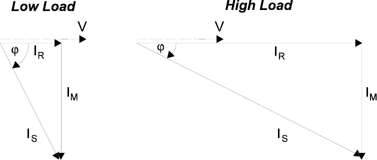
Figure 6.11:
Current vectors in an AC induction motor
Therefore, the central part of the vector control system is the active motor model, which
continuously models the conditions inside the motor:
• Continuously calculates in real time the torque-producing current by
implementing the following activities:
− Stores the motor constants in memory to be used as part of the
calculation
− Measures stator current and voltage in each phase
− Measures speed (with encoder) or calculates speed (no encoder)
• Continuously calculates in real time the flux-producing current
• Implements the speed control loop by comparing the speed feedback with the
speed setpoint to provide an error output to the torque control loop
• Implements the torque control loop by comparing the active torque, calculated
from the current and speed feedback, to provide an error output to the PWM
switching logic controller
• Constantly updates this information and maintains tight control over the
process.
For adequate dynamic response of the drive, the model calculations need to be done at
least more than 2000 times per second, which gives an update time of less than 0.5 ms.
Although this is easily achieved with modern high speed processors, the ability to
continuously model the induction motor at this speed only became viable within the last
10 years or so with the development of 16-bit microprocessors. Initially, sufficient
processing power for vector control was quite expensive, but over a period of time, the
cost of the processors has come down and processing speed has increased significantly.
The main difference between a traditional fixed V/f ratio VVVF converter and a
modern vector control drive is almost entirely in the control system and the extent to
which the active motor model for vector control is implemented to control the switching
pattern of the IGBTs of the inverter.
170 Practical Variable Speed Drives and Power Electronics
The power circuit for a vector converter is almost identical to that used by a VVVF
drive:
•
Rectifier
to convert 3-phase AC to a DC voltage
•
Inductive choke
to reduce harmonics on the supply side
•
Dc link
with capacitor filter to provide a smooth and steady DC voltage
• An
IGBT semiconductor inverter bridge
to convert the DC to a PWM
variable voltage variable frequency output suitable for an AC induction motor
• A
microprocessor based digital control circuit
to control the switching,
provide protection and provide a user interface
Today, ‘standard’ AC variable speed drives from most reputable manufacturers
implement vector control to some degree. For example, sensorless vector control is
advertised as a performance feature with almost all modern AC drives.
There are essentially 3 basic types of control for AC variable speed drives today:
• Basic fixed V/f drive, provides fair speed control at a reasonable price and is
suitable for the control of centrifugal pumps and fans
• V/f sensorless vector drive, provides better speed regulation, better starting
torque and acceleration by implementing more/better control of the flux
producing current vector (flux-vector)
• Closed loop field oriented vector control drive, provides excellent speed and
torque control with DC like performance using cascaded PI control over
speed, torque as well as flux regulation. Dynamic performance is excellent.
(GYOILO^KJ<LJXO\KY
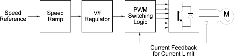
The control strategy of a fixed V/f drive is essentially
open-loop control
as shown below.
• The
speed reference
is taken from an external source and controls the voltage
and frequency applied to the motor.
• The speed reference is first fed into a ramp circuit to convert a step change in
the speed request to a slowly changing signal. This prevents electrical and
mechanical shock to the speed control system. The acceleration and
deceleration ramp times can be set by the user.
• The signal is then passed to a section that sets the magnitude of both the
voltage and frequency fed to the motor. The V/f ratio between the voltage and
frequency is kept constant at all times. It also sets the
rate of change
of these
two values, which determines the motor acceleration.
• The base voltage and base frequency used for this ratio are taken from the
motor nameplate.
• Finally, the signal passes to the PWM switching logic module, that controls
the switching pattern of the IGBT switches to provide the voltage pattern at
the output terminals according to the PWM algorithm (sine-coded, etc).
• There is usually no speed feedback from the motor. It is
assumed
that the
motor is responding to and following the output frequency (open-loop
control).
• The current feedback from the current transducer is there mainly for
protection, indication and to set a current limit, it is NOT used as part of the
control strategy.
Control systems for AC variable speed drives 171
Figure 6.12:
Block control diagram of fixed V/f drive
It is necessary to monitor the stator current flowing to the motor. The drive usually
monitors total current and cannot distinguish between I
m
and I
r
. This current is not used to
control torque, but is aimed at the following functions:
• Measures actual current for the I
2
t overload protection of the motor
• Provides protection of the power electronic components
• Provides a
current limit
, the control system reduces the frequency command
signal when the current exceeds a predetermined value. Usually, current limit
is set to 150% of the rated motor current.
• Some newer V/f drives provide
slip compensation
as a strategy for
improving the speed holding capability in an attempt to maintain relatively
constant motor speed even with changes in the motor load torque. As the
output torque increases, the motor current increases, which can be used to
adjust the output frequency of the converter. For example, at full rated load,
the full slip value can be added to the output frequency. With slip
compensation, improved speed regulation can be obtained from an induction
motor without a speed feedback device.
This method of open loop fixed V/f control is adequate for controlling steady-state
conditions and simple applications, such as pumps, fans and conveyors, which allow a lot
of time for speed changes from one level to another and where the consequences of the
changes in the process are not severe.
This type of drive is not well suited to the following:
• Applications where motors run at low speeds (below 5 Hz). The torque at low
speed is generally poor because the stator volt drop significantly affects the
magnitude of the flux-producing current. Many V/f drives include a ‘start
boost’ when allows the V/f ratio to be boosted at starting in an attempt to
improve the flux and consequently the starting torque.
• Applications which require higher dynamic performance.
• Applications that require direct control of motor torque rather than motor
frequency.
• The dynamic performance of this type of drive with shock loads is poor.
<LYKTYUXRKYYLR[^\KIZUXJXO\KYUVKTRUUV\KIZUX
The development of sensorless flux-vector drives was aimed at overcoming the main
shortcomings of the fixed V/f drives, mainly the loss of torque at low speeds.
172 Practical Variable Speed Drives and Power Electronics
This type of drive is often also called an open loop vector drive because its basic core is
still the fixed V/f ratio controller. But wrapped around this core are several additional
control components:
• A
current resolver (mathematical model)
that uses the measured stator
current to calculate (in real time) the two separate current vectors which
represent the flux-producing current (I
m
) and the torque-producing current (I
r
)
• A
high performance current limiter
which uses the torque-producing
current (I
r
) to rapidly adjust the frequency command to limit current
• A
flux regulator
which continuously adjusts the V/f ratio to maintain an
optimum control of the flux-producing current (I
m
)
• A
slip estimator
that provides accurate estimation of the rotor speed based on
the known motor parameters, without the use of an encoder. This provides
improved slip compensation under all conditions of speed and load.
The result is greatly improved torque, particularly at low speeds, to provide high
breakaway and acceleration torque and an improved dynamic response to shock loads.
However, this type of drive does not provide torque control, it is still a speed control
device. In addition, speed holding capability is substantially improved.
This type of drive can also be operated with an encoder, providing closed-loop control
of the speed. This substantially improves the speed holding capability of the VS drive
with speed regulation of 0.1%.
)RUYKJRUUVLOKRJUXOKTZKJ\KIZUXJXO\KY
Up to the end of the 1980s, high performance drive applications inevitably required the
use of a DC drive. However, the high maintenance requirements of DC drives have
encouraged the development of alternative solutions. Vector controlled AC drives have
evolved to provide a level of dynamic performance that has now exceeded that of DC
drives.
Closed-loop vector control is not required for every AC VSD application, in fact only
on a minority of applications. But there are a number of applications that inherently
require tight closed-loop control, with a speed regulation better than 0.01% and a
dynamic response better than 50 radians/sec. This dynamic response is about 10 times
better than that provided by standard V/f drives.
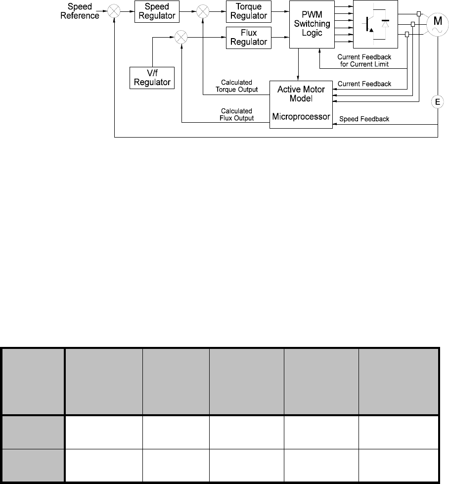
The control block diagram for a high performance vector control AC drive system is
essentially a cascaded closed-loop type with speed and torque control loops:
• There are two separate control loops, one for
speed
and the second for
current
. This control strategy is similar to that used for the control of a DC
drive.
−
Speed loop
controls the output frequency, proportional to speed
−
Torque loop
controls the motor in-phase current, proportional to
torque
• The
speed reference
command from the user is first fed into a comparator,
from where the error controls the speed regulator
• The speed error signal becomes the setpoint for the torque (current) regulator.
This signal is compared to the calculated current feedback from the motor
circuit and the error signal determines whether the motor is to be accelerated
or decelerated
Control systems for AC variable speed drives 173
• There is a separate control loop for the flux current (V/f regulator)
• Finally, the signal passes to the PWM and switching logic section, that
controls the IGBTs in such a way that the desired voltage and frequency are
generated at the output according to the PWM algorithm (sine-coded, star
modulation, VVC, etc).
Figure 6.13:
Block diagram of the flux-vector converter control circuit
Although a shaft mounted incremental encoder can be used to measure speed in an AC
drive, it is often considered to be an additional expense. In some cases it is difficult to
mount on the motor, for example when motors have integral brakes. Even when an
encoder is not used, the cascaded closed loop control can still be implemented because
speed can be calculated by the active motor model, but with a lower level of accuracy due
to the difficulty of calculating slip, particularly at very low speeds. Vector controlled
drives which do not use encoders are usually referred to as
sensorless vector drives
. The
dynamic response of vector control drives, which do not use an encoder, is usually
inferior to those that do.
The following are some interesting figures that have been presented by one of the
leading manufacturers of variable speed drives:
*)JXO\K
]OZN
KTIUJKX
<LLR[^
\KIZUX
YKTYUXRKY
Y
<LLR[^
\KIZUX]OZN
KTIUJKX
,OKRJ
UXOKTZKJ
YKTYUXRKYY
,OKRJ
UXOKTZKJ]OZN
KTIUJKX
9VKKJ
GII[XGI_
:UXW[K
XKYVUTYK
mSYKI SYKI mSYKI mSYKI mSYKI
Typical applications for this type of high performance VS drive are:
• Crane and hoist drives
• Rewinders on paper and steel-strip lines
• Paper machines
174 Practical Variable Speed Drives and Power Electronics
• Printing machines
• Positioning systems for automated manufacturing lines
• etc
When setting up high performance VSD controllers, a modest proportional gain gives a
good transient response, while the integral gain gives high steady state accuracy. PI-
controllers have the advantage that they can maintain a non-zero output to drive the
converter although their input is zero. This is an advantage in closed-loop control because
high accuracy should lead to zero error at the controller input.
Suitable values of P and I determine the step and ramp parts of the response
respectively and have to be calculated for each inverter–motor–load combination.
• The
values of
P
and
I
for the speed loop
are dependent on the motor flux,
load friction and inertia as they influence the response of speed to current.
• The
values of
P
and
I
for the current loop
depend on the inverter gain,
motor resistance and leakage inductance, since they influence the response of
current to the motor frequency.
In modern digital drives, the P and I values for both current and speed loops can be set
by keypad or, alternatively, most modern digital drives usually include an algorithm for
self-tuning. This removes the difficulties of ‘tuning the loops’, which was traditionally
necessary with older analog DC drives. The P and I gains of the speed loop can be setup
during commissioning to meet application requirements and seldom need to be changed.
There are a number of disadvantages of the vector controlled AC drive, when compared
to a DC drive:
• The vector controller is far more complex and expensive when compared to
the simple cascade controller of a DC drive.
• Encoder speed feedback is usually necessary to obtain accurate feedback of
the motor shaft speed. Fitting these encoders to a standard squirrel cage AC
induction motor is often difficult and makes the motor more expensive. In
recent years, ‘Sensorless’ vector control has been developed where an encoder
is not required. The approximate speed is calculated by the processor from the
other available information, such as voltage and current. However, the speed
accuracy and dynamic response of these drives is inferior to those using
encoders.
• The nature of the drive itself often requires the AC motor to operate at high
torque loadings at low speeds. The standard squirrel cage AC induction motor
then requires a separately powered cooling fan, installed at the ND end of the
motor.
• Regenerative braking is more difficult with a vector drive than with a DC
drive. Resistive type
dynamic braking
systems are most often used with AC
vector control drives.
)[XXKTZLKKJHGIQOT')\GXOGHRKYVKKJJXO\KY
3KZNUJYULSKGY[XOTMI[XXKTZOT\GXOGHRKYVKKJJXO\KY
Current feedback is required in AC variable speed drives for a number of purposes:
•
Protection
, short circuit, earth fault and thermal overload in motor circuits
Control systems for AC variable speed drives 175
•
Metering,
for metering and indication for the process control system
•
Control
, current limit control and current loop control. Several methods have
been developed over the years to measure the current and convert it into an
electronic form suitable for the drive controller. The method chosen depends
on the required accuracy of measurement and the cost of implementation. The
main methods of measurement are as follows:
•
Current shunt
, where the current is passed through a link of pre-calibrated
resistance. The voltage measured across the link is directly proportional to the
current passing through it. This method was often used in drives with analog
control circuits.
•
Hall effect sensor
, where the output is a DC voltage, which is directly
proportional to the current flowing through the sensor. High accuracy and
stability over a wide current and frequency range are amongst the main
advantages of this device. This device is commonly used with modern digital
control circuits.
The performance of a normal core type current transformer is usually not adequate for
power electronic applications because its performance at low frequencies is poor and
accuracy of measurement of non-sinusoidal waveforms is inadequate. The main methods
of current measurement are described in detail in Appendix B.
)[XXKTZLKKJHGIQOTMKTKXGRV[XVUYK<<<,JXO\KY
The primary need for current feedback in general purpose VSDs is inverter switching
device protection. During short circuit or earth fault conditions, the device current will
rise rapidly. If the power electronic switching device, such as an IGBT, BJT, GTO or
MOSFET is not switched off quickly, it will be damaged and will fail. VSD reliability
depends on the fast and accurate sensing of over-current conditions.
The secondary need for current feedback is to perform current limiting. Early versions
of AC VVVF converters did not have a current limiting feature and would simply shut
down if the load became too high, requiring manual reset by an operator. This increased
downtime and gave VVVF converters a poor reputation in many industries, where
overload trips were common. Modern VSDs use current feedback to limit the output
current when high loads are encountered.
Current limiting is not the same as current control. Current control means that the
current is being controlled at all times, whether it is high or low. Current limiting means
that some action is taken to stop the current exceeding the desired limit point. This action
may be only indirectly related to current, such as a change in frequency or voltage.
A third need for current feedback is to provide a current signal roughly proportional to
load. This signal may be used internally by the drive to optimize motor volts/hertz or
provide slip compensation, where the frequency is increased slightly as load increases to
improve speed regulation. The signal may also be made available for external use, by the
user, as a load indication signal. As outlined earlier in this chapter, the stator current of
the motor is only roughly proportional to the mechanical load, since the stator current is
the vector sum of the magnetizing current I
M
and the torque-producing current I
R
.
Motor current feedback can also be used to provide thermal protection of the motor.
This requires a thermal model of the motor to be implemented in the drive control system,
using frequency and current feedback and motor parameters to estimate the internal
temperature of the motor, using an I
2
t replica in the converter. If current level exceeds a
176 Practical Variable Speed Drives and Power Electronics
set point for a period of time, the motor protection will trip the drive and give an
indication of a motor thermal overload.
)[XXKTZLKKJHGIQOTNOMNVKXLUXSGTIK\KIZUXJXO\KY
High performance drives, such as vector controlled drives, employ field oriented control
and require current feedback as an integral part of their control loops. In these cases
motor current is not simply limited at a pre-defined level. It is controlled to match a
continuously changing torque demand. The vector components of the stator current in
each phase are calculated, which requires current from all three phases. This can be
achieved preferably with one hall effect CT in each output phase or alternatively two in
the output phases and one on the DC bus. If only two-phase sensors are used, the third
phase can be calculated from them, however the bus current sensor is still required for
device protection.
High accuracy motor current feedback is also necessary to provide control of motor
torque. Torque control is necessary in applications such as rewind/unwind systems,
hoists, winches, elevators, positioning systems, etc.
*)H[YI[XXKTZLKKJHGIQ
DC bus current feedback is suitable for switching device protection and current limiting
in most AC VSDs. To a lesser extent, it can provide some load indication if suitably
scaled. However, this is usually only accurate over a narrow range of speeds and loads, as
the signal must be synthesized from the bus current waveform. It is the preferred method
in general purpose drives, as it only requires a single current feedback device, reducing
complexity and cost.
Robust performance for a large variety of load types can be achieved through careful
implementation of DC bus current limiting. This is achieved by controlling the motor
frequency to maintain the bus current at or below the preset limit point. For example,
excessive loads may be encountered if a high inertia load is accelerated too quickly. This
may occur if the acceleration time on the VSD is set without regard to the load dynamics.
For example, consider an application where a 22 kW motor would take 10 secs to
accelerate a high inertia load at 150% rated torque and current. If the operator sets the
acceleration time to 5 seconds, this would require 300% rated torque and around 500%
current to accelerate the load. Clearly, a drive rated at 150% current overload will not be
able to achieve the desired acceleration time. In this situation, a modern well designed
VSD will not trip, but will modify its acceleration time to maintain the DC bus current at
the current limit point. While the operator may not have been able to achieve the desired
acceleration time, this is clearly preferable to the drive tripping on over current every time
it starts.
9VKKJLKKJHGIQLXUSZNKSUZUX
In closed-loop speed control of electric motors and positioning systems, the speed and
position feedback from the rotating system is provided by transducers, which convert
mechanical speed or position into an electrical quantity, compatible with the control
system.
The following techniques are commonly used today:
•
Analog speed transducer
, such as a tachometer generator (tacho-generator),
which converts rotational speed to an electrical voltage, which is proportional
Control systems for AC variable speed drives 177
to the speed, and transferred to the control system over a pair of screened
wires.
•
Digital speed transducer
, such as a rotary incremental encoder, which
converts speed into a series of pulses, whose frequency is proportional to
speed. The pulses are transferred to the control system over one or more pairs
of screened wires.
•
Digital position transducer
, such as a rotary absolute encoder, which
converts position into a bit code, whose value represents angular position. The
code is transferred digitally to the control system over a screened parallel or
serial communications link.
Analog speed transducers are increasingly being replaced by digital devices, which are
more compatible with modern digital control systems.
The main methods of speed measurement are described in detail in Appendix C.

7
9KRKIZOUTUL')IUT\KXZKXY
/TZXUJ[IZOUT
Although manufacturers’ catalogues try to make it as easy as possible, there are many
variables associated with the selection and rating of the optimum electric motor and AC
converter for a variable speed drive (VSD) application. In many cases, it requires
considerable experience to get the selection right. The reason why it is difficult is because
there is always an engineering trade-off between the following:
• The need to build in a margin of safety into the selection procedure
• The need to keep the initial cost to a minimum, by selecting the optimum type
and size of motor and converter for each application.
This chapter covers many of the principles for the correct selection procedure for AC
variable speed drives, which use PWM-type variable voltage variable frequency (VVVF)
converters to control the speed of standard AC squirrel cage induction motors.
The following checklist covers most of the factors that need to be considered:
• The nature of the application
• Maximum torque and power requirements and how these change with speed
• Starting torque requirements
• The speed range - minimum and maximum speed
• Acceleration & deceleration requirements (Is braking necessary?)
• Compatibility with the mains supply voltage
• Environmental conditions where the converter and motor are required to
operate, ambient temperature, altitude, humidity, water, chemicals, dust, etc
• Ventilation and cooling for the converter and motor
• Direction (uni- or bi-directional)
• Accuracy of the speed control
• Dynamic response (speed and torque response requirements)