Marcus P. Corrosion mechanisms in theory and practice
Подождите немного. Документ загружается.

(PSB)–grain boundary interactions are often observed to be preferential crack
initiation sites during CF, as well as localized pits around metallurgical heterogeneities.
The main need in fatigue crack initiation modeling is related to the quantitative
approach to local synergistic effects between environment and cyclic plasticity. In this sec-
tion, quantitative approaches to corrosion fatigue crack initiation from different electro-
chemical conditions are presented. Then improvement of such models is given through
corrosion-deformation interaction effects. Finally, an interesting example is given of the
coupling effects between cyclic plasticity and corrosion that must be taken into account to
improve the crack initiation resistance of duplex stainless steels in chloride solutions.
Classical Approaches to Corrosion Fatigue Damage
Electrochemical corrosion can be schematized as an “electronic pump or an
electronic circuit” related to oxidation and reduction reaction:
M → M
n+
+ ne
–
anodic dissolution
452 Magnin
together with a cation hydrolysis reaction: M
n+
+ nH
2
O → M(OH)
n
+ nH
+
.
Here M
n+
is a solvated ion, e
–
is an electrorn, and n represents the ion state of
charge. The electrons, liberated by the oxidation, must flow through the material M
to be consumed in an appropriate cathodic reaction. Beyond a solubility limit,
precipitates of hydroxide or hydrated oxide are formed, and this surface film can
provide a barrier to further dissolution. In fact, there are two film formation
mechanisms: the dissolution-precipitation mechanism addressed before and also the
solid-state oxidation process M + H
2
O → MO + 2H
+
+ 2e
–
. Some films are termed
“passive,” for stainless steels or aluminum alloys, for instance. These films can play
an important role in environment-sensitive crack initiation and fracture. Under
thermodynamic equilibrium conditions, the film stability may be inferred from
E = f(pH) diagrams, where E is the electrical potential related to the chemical free
energy G by G = –nEF, and F is Faraday’s number. At equilibrium, one can define
the electrode potential (related to ΔG) and the current density I (I ~ e
–ΔG*/RT
where
ΔG
*
is the activation energy of dissolution).
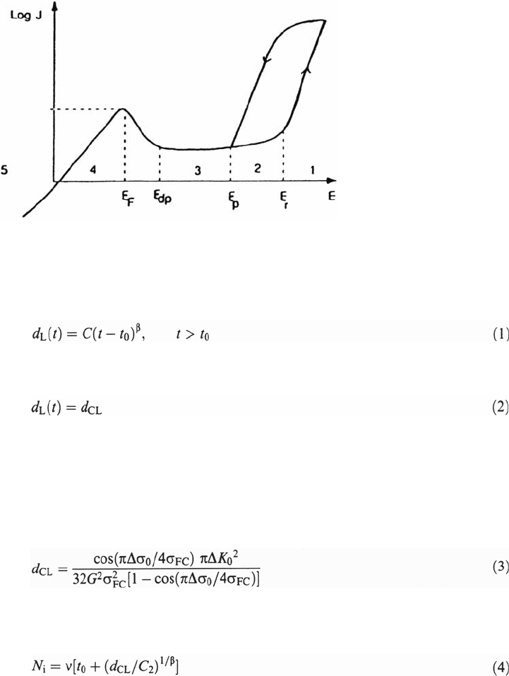
Thus, the relation E =f(I) gives different corrosion rates for a given metal in a
given solution. Figure 1 shows such a relation (polarization curve) in the case of an
austenitic stainless steel in an acidic Cl
–
solution. Five domains can be considered for
corrosion and corrosion fatigue damage:
(1) In zone 1, E > E
r
, pitting occurs by destabilization of the passive film. Pits
act as stress concentrators during fatigue. During CF under pitting conditions, pits
grow into the material. If such a pit reaches a critical depth d
CL
, a fatigue crack can
develop. The critical depth is then a function of the applied stress range [8].
Let us suppose the following conditions:
Constant corrosion conditions (pH, concentration of bulk solution)
Constant alternating load, dΔP/dt =0
Constant loading frequency dv/dt = 0
Copyright © 2002 Marcel Dekker, Inc.
It is well established that growth kinetics of corrosion pits are determined by a
simple power law such as
Corrosion Fatigue Mechanisms 453
Figure 1 General polarization curve for an austenitic stainless steel in acidic Cl
–
solutions.
where t
0
is the incubation time for pit nucleation. If the pit depth reaches the critical
value:
corrosion fatigue crack initiation occurs. The critical pit depth d
CL
depends on the
applied stress range Δσ
0
, the cyclic yield strength σ
FC
(which can be different from
the tensile yield strength), the fatigue crack growth threshold ΔK
0
, and the geometry
of the specimen, expressed in terms of a geometric factor G. It can be calculated by
elastic-plastic fracture mechanisms based on the Dugdale model [7]. Then d
CL
is,
given by the following equation:
The number of cycles to initiate a corrosion fatigue crack under pitting conditions
is, by combining the previous equations with N = tv,
The dependence of N
i
on the applied stress range Δσ
0
, calculated according to the
previous equation, is schematically represented in Figure 2a. Also, under pitting
conditions no corrosion fatigue limit exists. For N
i
≤ vt
0
, the influence of corrosion
on the fatigue crack initiation life disappears (only if pitting is the necessary effect).
Then, the lifetime is determined by the air fatigue behavior. Figure 2b shows an
example for which the proposed calculation of N
i
seems quite appropriate.
Nevertheless, the main problem is related to the fact that the coefficients C and β of
the pit kinetics are often not constant during cycling; it is a clear example of a
cooperative effect between plasticity and electrochemistry that needs finer analyses.
Copyright © 2002 Marcel Dekker, Inc.
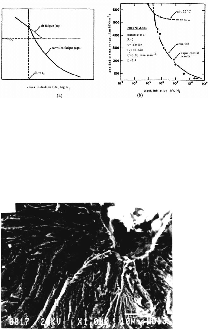
Figure 3 illustrates the fatigue crack initiation from a pit in a face-centered
cubic (fcc) Fe-Mn-Cr alloy cyclically deformed at low strain rate in a Cl
–
solution.
In many multiphase engineering materials, the presence of constituent particles
favors pitting and crack initiation.
(2) In zone 2, E
p
< E < E
r
, pits are repassivated. If the plastic strain amplitude
is too small for localized depassivation (by slip band emergence), pits will
454 Magnin
Figure 2 Corrosion fatigue crack initiation by pitting corrosion: (a) Schematic
representation of a σ-N curve. (b) Comparison of experimentally and theoretically derived
fatigue lives for the 20Cr-Ni-Mo alloy in 30 g/L NaCl solutions [8].
Figure 3 Crack initiation from a pit for a Fe-17Mn-13Cr alloy during CF in a 110°C Cl
–
solution at a plastic strain amplitude Δε
p
/2 = 4 × 10
–3
and a strain rate ε
·
= 10
–5
s
–1
.
Copyright © 2002 Marcel Dekker, Inc.
not grow and the CF behavior is then close to that in air. On the other hand, pits
can grow if mechanical depassivation occurs and the CF behavior is then close to
that of zone 1.
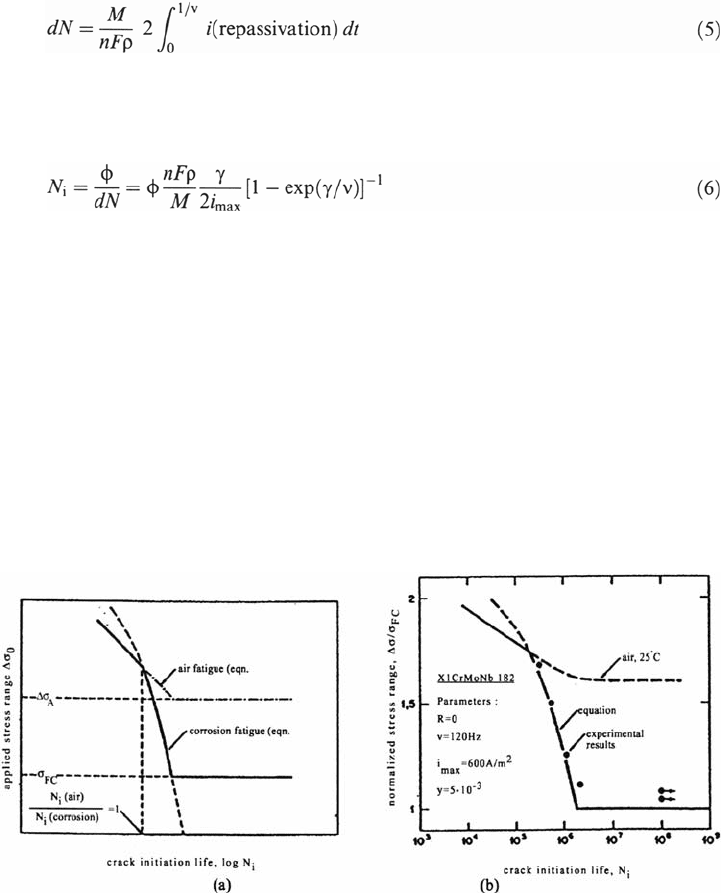
(3) In the passive region 3, a competition between the kinetics of depassivation
by slip and that of repassivation takes place. Thus the influence of the plastic strain
amplitude and strain rate is quite obvious. In the same mechanical conditions as in
(1), the quantity of matter dissolved per cycle (related to a distance) in the
depassivated slip bands can be expressed, using Faraday’s law:
Corrosion Fatigue Mechanisms 455
where i (repassivation) is generally of the form i
max
exp(–γt) with γ taken as a
constant. Then N
i
= N (for dN = d
c
). If d
c
is taken as the grain size φ, for instance, then
A schematic representation of the equation is given in Figure 4a and corresponding
experimental results are shown in Figure 4b.
Neverthless, one of the main problems is that the repassivation law evolves
during cycling as shown in Figure 5. This result also emphasizes the synergy in
CF that leads to a complex predictive approach.
(4) In zone 4, generalized dissolution occurs, which is generally quite
dangerous for materials even without stress! In some cases, general corrosion can,
however, blunt the cracks, which improves the fatigue life.
Figure 4 (a) Schematic representation of a σ-N curve for CF crack initiation under passive
conditions. (b) Comparison of experimentally and theoretically derived fatigue lives for the
X1 Cr MoNb 182 alloy in 30 g/L NaCl at 80°C [8].
Copyright © 2002 Marcel Dekker, Inc.
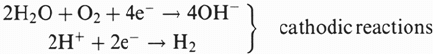
(5) In zone 5, cathodic reactions are favored. If reduction of hydrogen occurs,
we can have
2H
+
+ 2e
–
→ H
2
→ 2H
adsorbed
→ H
2
H
ads
→ H
absorded
which can induce hydrogen diffusion and/or transport by dislocations, often leading
to macroscopic brittle fracture under stress.
The electrochemical approach presented here has many limitations. First of
all, the kinetics of the electrochemical reactions are closely dependent on the
cyclic plasticity and the number of cycles [9,10]. Thus, predictive laws are very
complex. Moreover, these laws use the local current densities, which are very
difficult to model. Finally, this approach does not really take into account the local
corrosion-deformation interactions (CDIs) and the effects of the corrosive solution
on the deformation mode. Indeed, such synergetic effects between corrosion and
deformation can be of prime importance; the following examples emphasize the
role of CDI in crack initiation processes.
456 Magnin
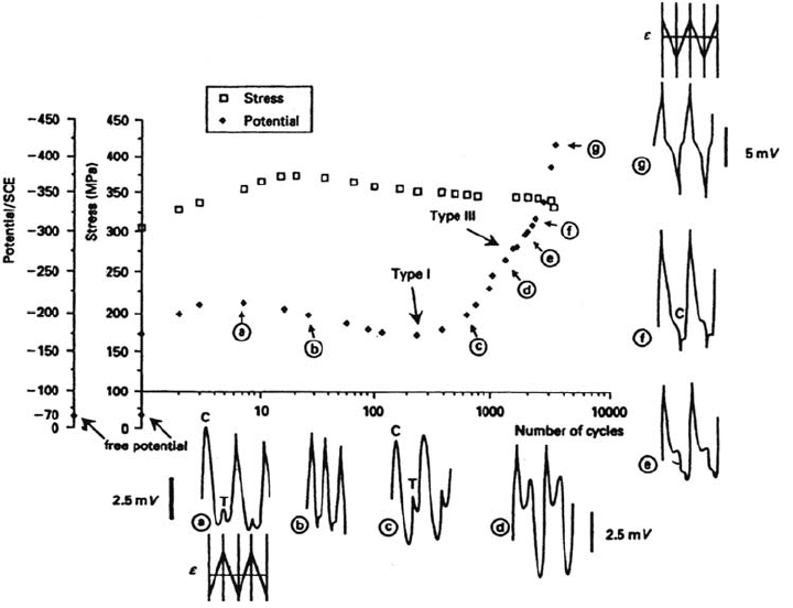
Figure 5 Simultaneous evolution of the cyclic stress σ, the average potential, and the
shape of the cyclic potential transients for a 316L alloy in 30 g/L Na Cl (Δε
p
/2 = 10
–3
,
ε
·
= 10
–2
s
–1
).
Copyright © 2002 Marcel Dekker, Inc.
Influence of Cyclic Plasticity on Electrochemical Reactions
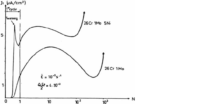
The evolution of dissolution current density transients during cycling of ferritic and
austenitic stainless steels in NaCl solutions is shown in Figure 6, where curves
J
T
= f(N) are plotted. Here J
T
is the peak current density related to the depassivation
process due to cyclic plasticity, and N is the number of cycles. During the first cycles
the amount of dissolution increases, particularly at a high strain rate. One of the
ferritic steels exhibits twinning, which induces a more marked depassivation during
cycling, compared with the behavior of the second ferritic steel, which deforms by
pencil glide [11].
Figure 6 clearly illustrates the influence of the deformation mode on the
electrochemical reactions and the evolution of such electrochemical transients as
a function of N (i.e., the localization of the plastic deformation with a decrease of
J
T
after the first cycles and then the formation of microcracks with a new increase
of J
T
until fracture due to a more difficult repassivation process).
PSBs and intense slip bands are very prone to specific dissolution, not only
for passivated alloys but also in conditions of generalized dissolution as shown in
Figure 7 for copper single crystals in NaClO
4
solution [9].
As soon as the PSBs form, the anodic current increases even though the applied
plastic strain remains constant. This effect is related not only to the localization of the
cyclic plasticity but also to the influence of the dislocation microstructure of PSBs on
the free energy of dissolution (–ΔG) and the energy of activation (ΔG
*
) [10].
Moreover, cyclic plasticity has also been shown to promote localized pitting
well below the pitting potential without stress [10]. Thus, for the ferritic Fe-26Cr-
1 Mo stainless steel in 3.5% NaCl solution, a high strain rate ε
·
promotes strain
localization at grain boundaries, which induces intergranular pitting for an applied
potential of about 400 mV below the pitting potential without stress effect.
Corrosion Fatigue Mechanisms 457
Figure 6 J
T
= f(N) curves for stainless steels during CF in a 3.5% NaCl solution.
Copyright © 2002 Marcel Dekker, Inc.
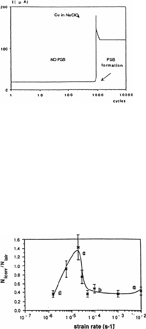
The applied strain rate (or frequency) is a very sensitive parameter for CF
damage. Figure 8 gives an interesting example for an Al-Li 8090 alloy in NaCl
solutions. N
i
is defined as the number of cycles to obtain a rapid 3% decrease of the
saturation stress [10]. At high strain rate (ε
·
> 5 × 10
–3
s
–1
), the anodic dissolution
occurs at slip band emergence and induces an enhancement of the transgranular
mechanical microcracking. At medium strain rate (5 × 10
–5
s
–1
< ε
·
< 5 × 10
–3
s
–1
),
pitting is favored and responsible for crack initiation. So when the plastic strain
decreases, pitting is more profuse (because of time) and the reduction in the fatigue
life to crack initiation is more pronounced in comparison with air.
458 Magnin
Figure 7 Influence of the PSB formation on the dissolution current for Cu single cyrstals in
NaClO
4
[9].
Figure 8 Influence of strain rate on 8090 Al-Li alloy fatigue life to crack initiation in a
3.5% NaCl solution for Δε
p
/2 = 4 × 10
–3
at free potential.
Copyright © 2002 Marcel Dekker, Inc.
At low strain rate (5 × 10
–6
s
–1
< ε
·
< 5 × 10
–5
s
–1
), the fatigue time to initiation
increased by blunting of the mechanically formed microcracks because of
generalized pitting that acts as general corrosion. At very low strain rate (ε
·
< 5 ×
10
–6
s
–1
), CF crack initiation occurs by intergranular stress corrosion due to
localized dissolution at grain boundaries. The rapid occurrence of stress corrosion
cracking (SCC) induces a marked decrease of N
i
.
Softening Effect due to Anodic Dissolution
CF tests on smooth specimens were performed at room temperature on a 316 L
austenitic stainless steel in a 0.5 N H
2
SO
4
solution at different electrochemical
potentials and for a prescribed plastic strain amplitude of 4 × 10
–3
(ε
·
= 10
–2
s
–1
).
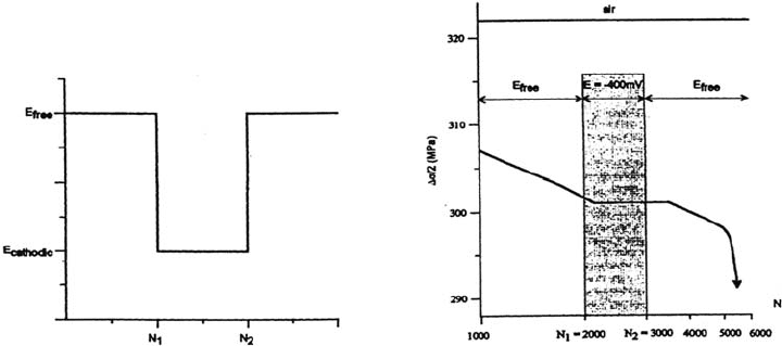
The depassivation-repassivation process occurs in a very regular way, well
before any microcracks can form [11]. It is of particular interest to follow the
evolution of the maximum flow stress in the corrosive solution at free potential
and at imposed cathodic potential and to compare this evolution with that
observed in air (Figure 9). It clearly appears that (a) a cyclic softening effect
occurs at the free potential in comparison with the behavior in air; (b) this soft-
ening effect disappears when the cathodic potential is applied (and the anodic
dissolution is markedly reduced), after about 150 cycles; (c) the softening effect
then occurs in the same way when the free potential is reestablished; and (d) a
delay in the evolution of the flow stress with regard to the number of cycles for
which a potential change is imposed can be observed for the free potential to the
cathodic potential change (and vice versa).
This effect has also been observed during creep in corrosive solutions for
copper [1]. It corresponds to the time during which vacancies due to dissolution are
still acting on the dislocation mobility.
The macroscopic cycling softening effect observed in H
2
SO
4
solution at room
temperature (which is not due to microcracking) is very relevant to take into account
Corrosion Fatigue Mechanisms 459
Figure 9 Evolution of the peak stress Δσ/2 during cycling in a 0.5 N H
2
SO
4
solution at
free potential for Δε
p
/2 = 4 × 10
–3
and
ε
·
= 10
–2
s
–1
compared with the air behavior.
Copyright © 2002 Marcel Dekker, Inc.
quantitatively the local dissolution-deformation interactions that will lead to the
fatigue crack initiation process.
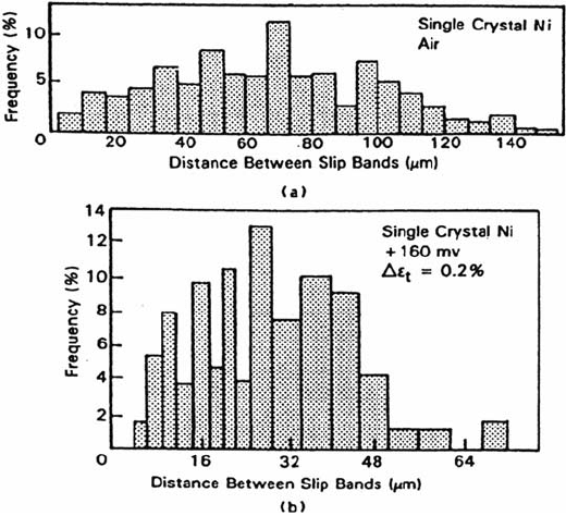
Influence of Corrosion on PSB Configurations
Electrochemical control of corrosion has been shown to affect significantly the
morphology of surface deformation. A modification of the number of persistent
slip bands (PSBs) and of the slip offset height in PSB has been observed for Ni
single crystals [4] in 0.5 N H
2
SO
4
and in copper single crystals [4,9] according to
the applied potential, in comparison with air. It is easy to understand that such
influences on PSB distribution will affect the crack initiation conditions. Figure 10
shows histograms of the PSB distribution produced on monocrystalline nickel in
0.5 N H
2
SO
4
at a constant strain amplitude.
Experiments conducted at the corrosion potential and at +160 mV/SCE
result in a reduction of the inter-PSB distance and a reduction of slip offset height.
An Example of Mechanical and Electrochemical Coupling Effects:
The CF Crack Initiation Mechanisms of a Two-Phase Stainless Steel
in NaCl Solutions
Mechanical and electrochemical coupling effects are generally the key for
understanding the crack initiation mechanisms in multiphase alloys. This is
460 Magnin
Figure 10 Histograms of distance between PSB clusters, from the replicate Ni single-
crystal specimens fatigued for 1000 cycles under total strain control Δε
t
. Shear strain = 0.12%,
(a) air and (b) +160 mV/SCE in 0.5 N H
2
SO
4
[4].
Copyright © 2002 Marcel Dekker, Inc.
clearly illustrated for a duplex α/γ stainless steel (without nitrogen) in a 3.5% NaCl
solution at pH 2 and free potential [11]. At low plastic strain amplitude, the softer
γ phase is depassivated but this phase is cathodically protected by the non–
plastically deformed α phase [11]. This coupling effect reduces the dissolution of
the γ phase and delays CF damage, which is not the case at higher strain amplitude
when the α phase is also depassivated by slip band emergence.
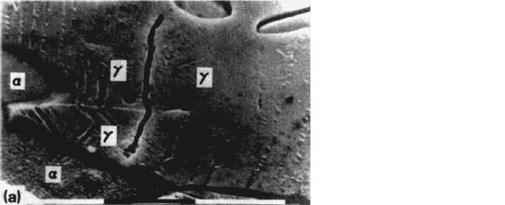
Observations of the crack initiation sites by scanning electron microscopy
showed that at low plastic strain amplitudes (Δε
p
/2 < 10
–3
) for which the fatigue
resistance of the α-γ alloy is close to that of the γ alloy, cracks nucleate only in the
austenitic phase (Fig. 11a), but at higher strain amplitudes (Δε
p
/2 < 10
–3
), the first
cracks nucleate principally in the ferritic phase (Fig. 11b). The excellent CF
resistance of duplex stainless steels (for Δε
p
/2 < 10
–3
) can then be understood through
the electrochemical and mechanical coupling effects on crack initiation processes.
CORROSION FATIGUE PROPAGATION MECHANISMS
Phenomenology
One can find an enormous amount of mechanistic work about corrosion fatigue
crack growth in the literature (see, for instance, Refs. 4,6,7,12). The aim of this
section is not to review such studies but to analyze the possible mechanisms at the
crack tip leading to crack advance. The question is, “What is the crack tip driving
force that controls the corrosion fatigue crack growth?” among the different
mechanical (stress, strain, strain rate) and chemical (dissolution, film formation,
hydrogen production) effects.
Figure 12 shows the influence of different environments on the crack growth
rate of a classical industrial steel [4]. Moist air is shown to have a marked influence
on the crack growth rate in comparison with vacuum. Crack tip velocity is very
sensitive to sodium chloride solution.
In fact, one must distinguish between long crack growth and short crack
growth. For long crack growth, using linear elastic fracture mechanics (LEFM),
Corrosion Fatigue Mechanisms 461
Figure 11 Crack initiation in a duplex stainless steel at ε
·
=2× 10
–3
s
–1
. (a) In the γ phase
at Δε
p
/2 = 3 × 10
–4
. (b) In the α phase at Δε
p
/2 = 4 × 10
–3
.
Copyright © 2002 Marcel Dekker, Inc.