Massoud M. Engineering Thermofluids: Thermodynamics, Fluid Mechanics, and Heat Transfer
Подождите немного. Документ загружается.

352 IIIb. Fluid Mechanics: Incompressible Viscous Flow
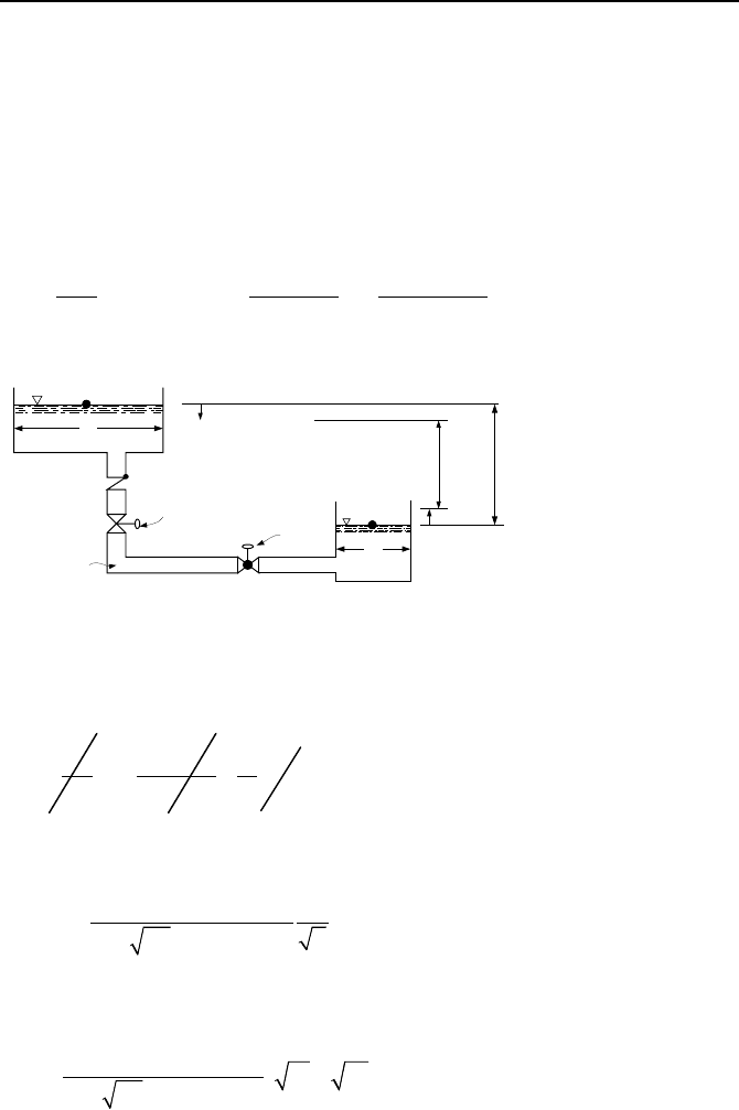
Flow Between Reservoirs in a Quasi-steady Process (Gravity Fill)
In this problem we are interested in finding the time it takes for the height between
two large water reservoirs to drop to a specified value. The reservoirs are con-
nected by a pipe, which also includes valves and fittings (Figure IIIb.6.4). Ini-
tially, both valves are closed and the height difference in water levels is h
1
. At
time zero, both valves are fully opened. We use continuity and momentum equa-
tions. If s and s’ show change in water level at time t, then sA
1
= s’A
2
. At time t,
we also have h(t) = h
1
– (s + s’), thus dh = –(1 + A
1
/A
2
)ds. From a mass balance:
2
11
12 1 2
hh
() /
41/1/1/
ddd
V A ds dt A
AA A A
π
−
== =−
++
s
L,d,
A
1
K
Isolation valve
Regulating valve
h
1
s'
h(t)
A
2
1
2
Figure IIIb.6.4. Unsteady flow of viscous fluid between reservoirs
Having found velocity in terms of h, we use the momentum equation to find
another relation for V and h. This is given by Equation IIIa.3.41 (with h
s
= 0):
0h)()(
1
2
1212
2
1
2
2
2
1
=+−+−+
−
+
µ
¶
´
∂
∂
f
gZZgPP
VV
ds
t
V
ρ
substituting for Z
2
– Z
1
= –h(t), for h
f
= (fL/d + K)V
2
/2g, and for V in terms of h,
we find
()
1/2
2
12
4( / K) h
21/ 1/ h
f
Ld d
dt
dgA A
π
+
=−
+
Integrating this relation between time zero (h = h
1
) to any time at which h = h
2
, we
find that the time t is given by:
1/2
12
2
12
8( / K)
(h h)
2 (1/ 1/ )
fL d
t
dgA A
π
+
=−
+
IIIb.6.5
6. Unsteady Internal Incompressible Flow 353
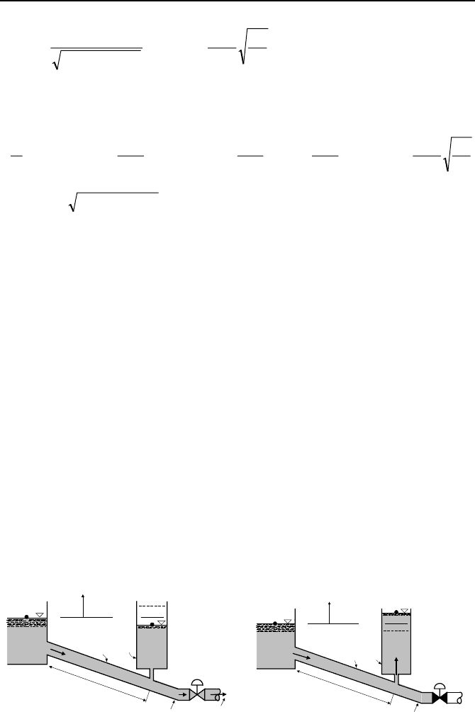
Time to Fill Drained Pipelines
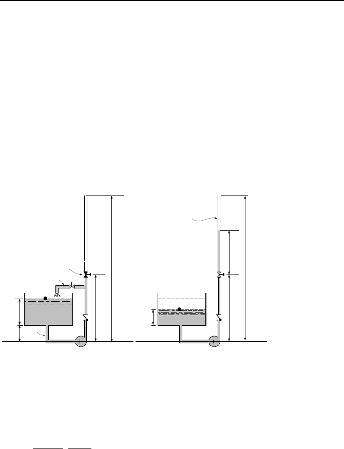
The time it takes to fill a drained pipeline is of special interest in many engineer-
ing applications. Examples include buildings spray system for fire protection or a
nuclear reactor containment building spray train for protection against excessive
pressurization in the case of a high-energy line break. Let’s consider a simple
case of filling a straight vertical pipe of diameter d and flow area a with water as
shown in Figure IIIb.6.5. Initially, water height in the reservoir is h
0
and at an ele-
vation Z
1
= Z
T
+ h
0
, with respect to the pump centerline. Also the control valve is
closed, the pump is circulating water, and the discharge pipe is full of water up to
the control valve elevation, Z
V
. At time zero, the bypass line is shut and the con-
trol valve starts to open. It takes
θ
0
seconds for the control valve to reach the full
open position. The control valve loss coefficient K
V
versus area is known. We
want to find the time it takes to fill the drained piping downstream of the control
valve.
P
1
Control Valve
Pump
Datum Plane
h
0
Z
T
Z
2
Z
V
2
1
y
P
1
K=f(t)
Control Valve
Pump
Datum Plane
Z
2
Z
V
2
A
h
1
a
a =
π
d
2
/4
Bypass Line
Figure IIIb.6.5. Filling of a partially drained pipeline
The bypass line is considered in this problem to avoid dealing with pump start
up and the associated inertia, as discussed in Chapter VIc. To find the fill up time,
we note that at time t, water has reached point A at an elevation Z
A
. We write the
momentum equation between points 1 and A. Equation IIIa.3.45 for water:
Wfricvelgravstatpump
WV
PPPPP
dt
md
a
L
)()
h
(
∆+∆+∆+∆−∆=
+
¦
IIIb.6.6
where L
V
is the length of the suction and discharge piping up to the control valve.
We also have:
∆P
stat
= P
A
– P
1
∆P
grav
=
ρ
W
g(h + Z
V
– Z
1
) =
ρ
W
g(h + Z
V
– Z
T
– y)
∆P
vel
= [1 – (a/A
1
)
2
]
2
W
m
/(2
ρ
W
a
2
)

354 IIIb. Fluid Mechanics: Incompressible Viscous Flow
∆P
fric
= [f(L
V
+ h)/d + ΣK(t)]
2
W
m
/(2
ρ
air
a
2
)
32
2
1
cmcmcP
pump
++=∆
where we have expressed pressure increase over the pump in terms of mass flow
rate, with coefficients c
1
, c
2
, and c
3
are constants to match pump data. For the
sake of generality, we also apply Equation IIIa.3.45 to the air region:
airfricvelgravstat
airV
PPPP
dt
md
a
ZZ
)()
h
(
2
∆+∆+∆+∆−=
−−
¦
IIIb.6.7
Assuming Ma number remains below 0.3, we may ignore the compressibility ef-
fect of air hence,
Wair
mm
=
∆
P
stat
= P
2
– P
A
∆P
grav
=
ρ
air
g(Z
2
– Z
V
– h)
∆P
vel
= 0.0
∆P
fric
= [f(Z
2
– Z
V
– h)/d + ΣK
air
]
2
W
m
/(2
ρ
air
a
2
)
If we substitute for the pressure differential terms and add up the two momentum
equations, we get:
{}
)2/(/]K)/([/]K)/([)2/(])/(1[
)]h()h([)()()(
22222
1
21232
2
1
amdLfdLfamAa
ZZgyZZgPPcmcmc
dt
md
a
L
airairWW
VairTVW
ρρ
ρρ
¦
++
¦
+−−−
−−+−−+−−−++=
¦
IIIb.6.8
where L and
ΣK are the total length and total loss coefficient of the suction and
discharge pipe, respectively. The loss coefficient is a given function of time since
the control valve is not a quick open valve. Also note that we dropped the sub-
script for the mass flow rate. The governing equation is a non-linear differential
equation. Since h and y appear in this equation, we must relate these to the mass
flow rate. Using the continuity equation will accomplish this. On the one hand we
know A
1
(h
o
– y) = ah. On the other hand
–A
1
dy/dt =
W
m
ρ
/
IIIb.6.9
Eliminating h in Equation IIIb.6.8, we obtain two simultaneous differential equa-
tions for y and
m
. The initial conditions are y(t = 0) = h
o
and
o
mtm
==
)0(
where
o
m
is the mass flow rate in the bypass loop prior to opening the control
valve. Since this set of equations must be solved numerically, P
1
and P
2
can be
specified as known functions of time. Indeed, in the case of a PWR or BWR con-
tainment during an accident, P
2
is a rapidly changing parameter. As discussed in
Chapter IIIc.2, we must also make sure that the flow of air out of the pipe remains
subsonic. Equation IIIb.6.8 can be simplified by ignoring the less significant terms.
6. Unsteady Internal Incompressible Flow 355
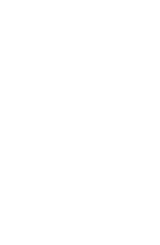
Time to Drain Vessels in Quasi-steady Process
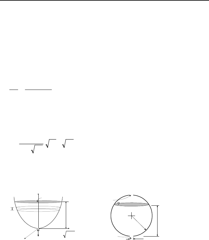
An example of unsteady incompressible flow is given here in the context of time it
takes to fill or drain vessels with liquid. The time dependent flow rate is obtained
from the solution to the conservation of mass and momentum equations. Fig-
ure IIIb.6.6 shows vessels, having a flow cross sectional area as a function of
height. In special cases such as a right circular cylinder, the flow area is a con-
stant, as was studied in Section 6.1. A general solution can be sought for simulta-
neous filling and draining. But we assume that liquid is drained only by gravity.
The rate of change of liquid mass in an elemental control volume is:
[]
o
m
dt
yyAd
dt
dm
−==
)(
ρ
where in the above equation, the vessel cross sectional area is assumed to be a
function of elevation. Time to empty a vessel can then be calculated if the func-
tion for A = f(y) is specified. If the cross sectional area is constant, A = A
v
, the
time to empty the tank from a height of y
1
to a height of y
2
can be readily found as:
[]
21
2
2
yy
gaC
A
d
V
−=
θ
IIIb.6.10
where a and C
d
are the drain flow area and discharge coefficient (generally be-
tween 0.65 and 1.0), respectively. Next we analyze a more comprehensive case of
a spherical reservoir.
x
y
z
h(t)
M(t)
A(h)
h2gaCm
do
ρ
=
dy
a and C
d
h(t)
R
R
Vent
Figure IIIb.6.6. Draining of an arbitrary and a spherical vessel containing incompressible
fluid
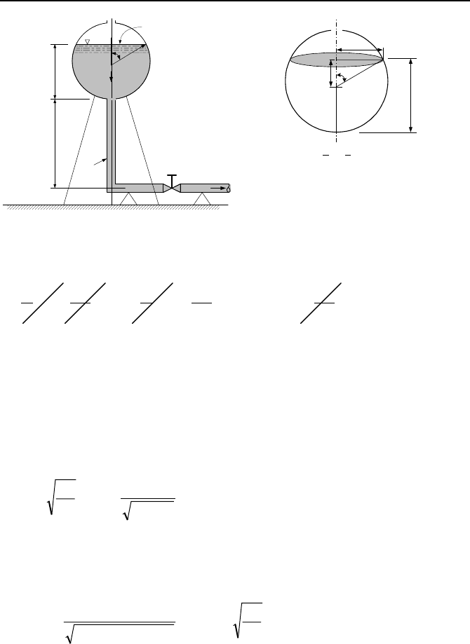
Time to Drain Spherical Reservoirs in Quasi-steady Process
To determine the time to empty a spherical reservoir with gravity draining, as
shown in Figure IIIb.6.7, we again use the continuity and the momentum equa-
tions, noting that the gravity head acts against the velocity head and the friction.
In this case however, the flow cross section in the tank also varies with elevation,
and thus with time. Ignoring initial liquid acceleration, noticing that P
1
= P
2
and
V
1
= 0, Equation IIIa.3.42
356 IIIb. Fluid Mechanics: Incompressible Viscous Flow
h(t)
H
T
d
β
R
A
1
2
a
R
β
Rsin
β
Rcos
β
R
h(t) = R + Rcos
β
A(t) =
π
(Rsin
β
)
2
h
0 <
β
<
π
Figure IIIb.6.7. Spherical water reservoir connected to the discharge piping
³
∂
∂
++++=++
2
1
2
2
2
21
2
1
1
h
2
)(
1
2
)(
1
ds
t
V
ggZ
V
PgZ
V
P
f
ρρ
simplifies to:
H
T
+ h = KV
2
/2g IIIb.6.11
where K = fL/d +
ΣK
i
and we dropped the subscript of the velocity term. We ob-
tain the second relation between V(t) and h(t) from the continuity equation, as flow
rate in the pipe is due to the rate of drop in water level in the reservoir, thus –
Adh/dt = VaC
d
where the exit flow area is aC
d
. Eliminating V between the mass
and the momentum equations yields:
hH
h
K
2
+
−=
T
d
d
Adt
g
aC
We should now solve the above differential equation, for which we make a change
of variable from h to
β
. While the range of h is 0 ≤ h ≤ 2R, the range of
β
is 0
≤
β
≤
π
. Using the new variable, we find water level as a function of time from:
µ
¶
´
=
µ
µ
¶
´
++
θ
π
β
ββ
π
0
0
3
3
K
2
cosH
sin
dt
g
aC
RR
d
R
d
T
We may switch to yet another variable,
ζ
= cos
β
and d
ζ
= –sin
β
d
β
, with –1 ≤
ζ
≤ 1. The resulting integral can be carried out twice by the method of separation
of variables. The result, expressed again in terms of
β
is
6. Unsteady Internal Incompressible Flow 357
dt
g
R
aC
d
R
d
T
µ
¶
´
−=
»
»
¼
º
«
«
¬
ª
µ
µ
¶
´
++
−
−
θ
π
ζ
ζ
ζζ
0
3
1
1
2
K
2
)1(H
)1(
Developing the left side integral by using three times, the method of integration by
part, yields:
t
g
R
aC
B
R
B
R
B
R
B
R
d
K
2
3
32
5
16
)31(
3
4
)1(
2
3
1
1
2/7
4
2/5
3
2/32
2
2/12
π
ζζζζ
−=
»
¼
º
«
¬
ª
+−−−−
−
where )1(H
ζ
++= RB
T
. Moody has evaluated various containers for gravity
draining. These include spherical and conical vessels as well as vertical and hori-
zontal cylinders.
Time Dependent Water Level In Surge Tanks
In hydroelectric power plants, a tunnel delivers water from the reservoir via the
penstock to the turbine. As shown in Figure IIIb.6.8, the control valve aborts the
flow of water to protect the turbine in a sudden loss of electric load. As is dis-
cussed in the next section, sudden acceleration or deceleration of fluid flow results
in the imposition of hydraulic forces, which may damage piping. A surge tank lo-
cated upstream of the control valve prevents such damage by diverting the flow
and damping oscillations. The surge tank also provides water in the case of a sud-
den load increase. The goal is to determine the surge tank water level as a func-
tion of time. The maximum water level occurs in the case of a loss of load fol-
lowed by sudden closure of the control valve. Water initially flows in the tunnel
at a speed of V
o
. Diameters of the tunnel and the surge tank are d and D, respec-
tively. The tunnel length from the dam inlet to the surge tank is L. At steady-state
operation, water in the surge tank is below the water level in the reservoir due to
the frictional head loss, H
L
= Z
A
- Z
B
where elevations Z
A
and Z
B
are measured
from an arbitrary datum.
y
1
2
Penstock
d
D
Lake
Surge Tank
L
Control
Valve
To Turbine
a
A
V
y
1
2
Penstock
d
D
Lake
Surge Tank
L
Control
Valve
a
A
V
Figure IIIb.6.8. Surge tank to regulate the operation of a hydraulic turbine
358 IIIb. Fluid Mechanics: Incompressible Viscous Flow
Upon a sudden closure of the control valve, water rushes into the surge tank.
This problem is similar to flow between reservoirs. However, we cannot use the
“quasi-steady” assumption. To determine the surge tank water level as a function
of time, we again use the conservation equations of mass and momentum. From
the conservation equation of mass for the surge tank we conclude:
VaA
dt
dy
ρρ
= IIIb.6.13
where V is flow velocity after the control valve is shut and y is measured from the
water surface in the reservoir. We now apply the one-dimensional momentum
equation, IIIa.3.44 between points 1 and 2. Since flow velocities inside the two
reservoirs are very small, we ignore both velocity heads and frictional losses in the
reservoirs. Integrating between points 1 and 2 along the streamlines, we get:
0
2
K
2
=++
L
V
L
y
g
dt
dV
IIIb.6.14
where K = fL/d +
ΣK
i
, V is flow velocity in the penstock, and L is the friction
length in the penstock. Note that the slope of the penstock does not appear in the
final equation. Hence, this analysis is applicable to any inclination including a
horizontal tunnel. We can now summarize Equations IIIb.6.13 and IIIb.6.14 as:
Vc
dt
dy
1
=
ycVc
dt
dV
3
2
2
+=
Coefficients c
1
, c
2
, and c
3
in these coupled first order and non-linear differential
equations are given as c
1
= d
2
/D
2
, c
2
= –(fL/D + ΣK)/(2L), and c
3
= –g/L. The
boundary condition for the first differential equations is that at time zero, y = –H
L
and for the second equation that at time zero, V = V
o
. One way to solve this set is
to take derivative of the first equation. Then substituting for dV/dt and for V from
the second and the first equation, respectively to obtain:
0)(
2
2
2
=++ by
dt
dy
a
dt
yd
Where a = –c
2
/c
1
and b = –c
1
c
3
. This is a second-order non-linear differential
equation, which could be solved numerically. It is interesting to explore the re-
sponse of the system in the absence of friction for which we can find an analytical
solution in closed form. In the absence of friction, the governing equation is:
0
2
2
=+ by
dt
yd
6. Unsteady Internal Incompressible Flow 359
L
h
V
i
.
V
o
.
B
C
Control
Volume
d, a
A
ttt
P
C
P
C
P
C
Figure IIIb.6.9. D
y
namic res
p
onse of a tank to influx and efflux of an incom
p
ressible
fluid
Since b is positive, the solution to this second order linear homogenous differen-
tial equation is given as:
tbCtbCty cossin)(
21
+=
Coefficients C
1
and C
2
can be found from two boundary conditions. First, at t = 0,
y = 0. Recall that earlier we said that at t = 0, y = –H
L
. However, we are not con-
sidering friction in this case, and hence, the surge tank water level is about the
same as the reservoir. For the second condition, we note that the flow rate going
to turbine at time zero would enter the surge tank right after the closure of the
valve at the same velocity. Hence, at t = 0, dy/dt = V
o
. Using the first boundary
condition, C
2
= 0. Using the second boundary condition, we can find C
1
which
upon substitution, we get:
t
L
g
D
d
V
g
L
d
D
y )sin(
0
¸
¸
¹
·
¨
¨
©
§
=
Expectedly, the oscillation of the water level in the surge tank is sinusoidal with
no damping effect due to lack of friction. The amplitude of the oscillation is given
by
dVgLD /)/(
0
=
λ
with a period of dLgDT /)/2(
π
= . There are various
designs for the surge tank. Examples include an orifice tank, a differential tank,
and a closed tank. In an orifice tank the inlet is equipped with an orifice to en-
hance friction. In a differential tank, the overflow is contained in a secondary tank
encompassing the primary surge tank. In a closed tank, the damping effect is pro-
vided by the work required to compress the air trapped on top of the tank water
inventory. Chaudhry, Parmakian, and Streeter discuss design and operation of
surge tanks.
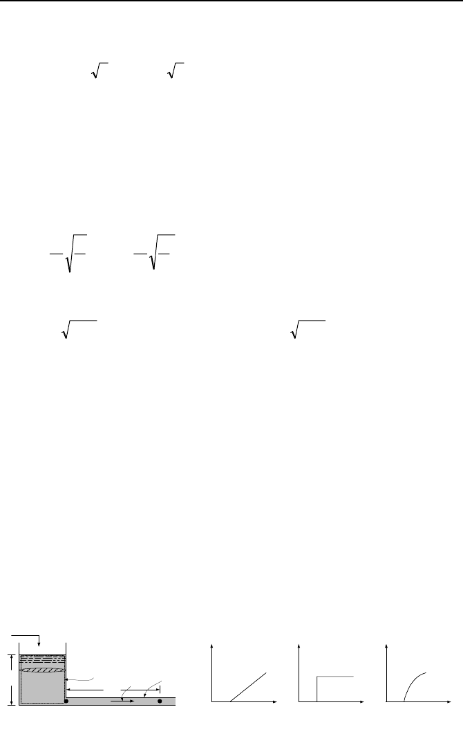
Liquid Level Fluctuation in Open Tanks
We now consider a case similar to the surge tank. Water enters an open tank at a
constant rate of
i
V
and leaves through a long pipe (Figure IIIb.6.9). Unlike the
surge tank problem, in this problem we let pressure downstream of the tank
change in a prescribed manner. The goal is to determine the response of the tank
water level to such pressure changes. For this purpose, we again combine the con-
servation equations of mass and momentum. We write the continuity equation for
the control volume representing the tank:

360 IIIb. Fluid Mechanics: Incompressible Viscous Flow
Adh/dt =
i
V
–
o
V
where A is the tank flow area and
o
V
is the rate of flow leaving the tank. We now
write the momentum equation for the long pipe extending between points B and C
as given by Equation IIIb.3.7:
(
)
22
o
2/V)/( adfLPP
CB
ρ
=−
At this point, all we need to do is to substitute for P
B
and P
C
in terms of h and
combine the continuity and the momentum equations. To find an analytical solu-
tion we consider the case of laminar flow in the pipe. For this case, f = 64
µ
/(
ρ
Vd).
For P
B
, we write P
B
= P
atm
+
ρ
gh, where we ignored the velocity heads. Similarly,
for P
C
, we write P
C
= P
atm
+
ρ
gh
C
. Substituting, we obtain:
21
h
h
cc
dt
d
=+ IIIb.6.15
where c
1
= 1/(BA), c
2
= (
i
V
+h
C
/B)/A, and B = 128vL/(
π
gd
4
). Vennard considers
three cases of linear, step, and sinusoidal fluctuations for h
C
. The solution to
Equation IIIb.6.15 is given by Equation VIIb.2.4. For example, for a step increase
in the downstream pressure, we find:
h = Ce
–t/BA
+ B
i
V
+h
C
IIIb.6.16
where C is the constant of integration to be found from the initial condition. That
is to say, at steady state, h
C
= h
Co
and h = h
o
. We can find the relation between h
Co
and h
o
by setting dh/dt = 0 in Equation IIIb.6.15:
h
o
= B
i
V
+ h
Co
IIIb.6.17
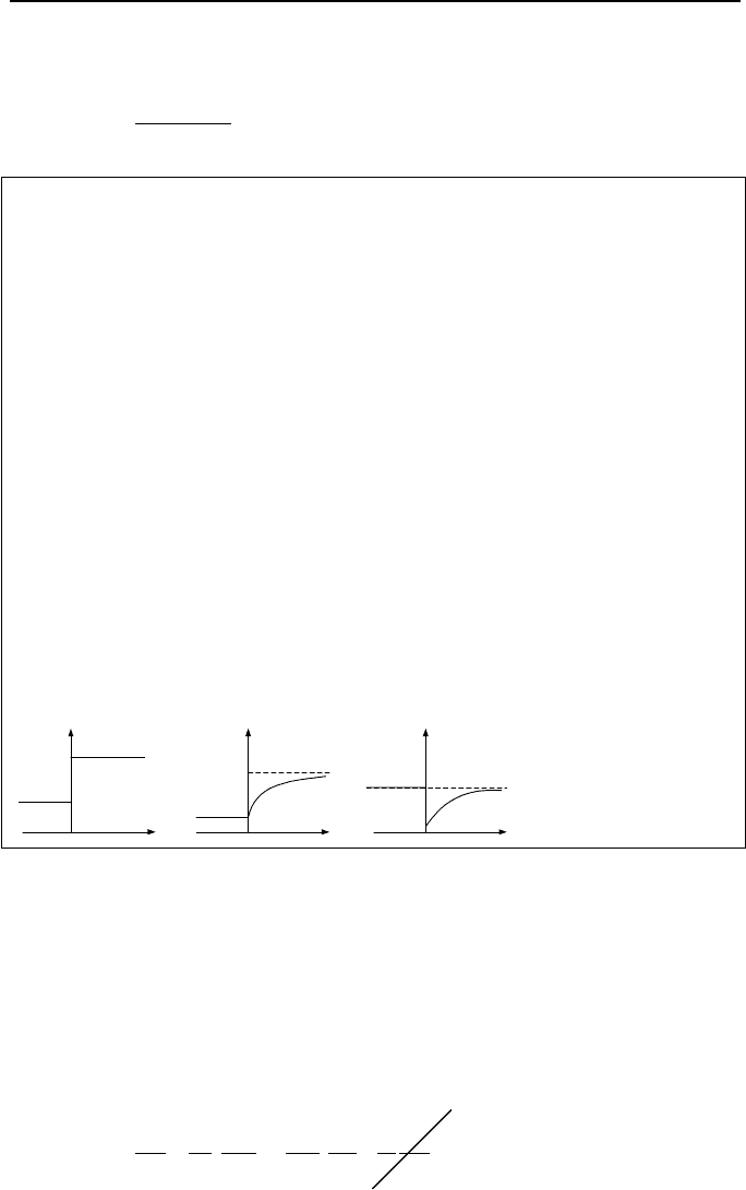
After a step increase from h
C
= h
Co
to say h
C
= h
C1
, Equation IIIb.6.16 gives the re-
sponse in water level as:
h = Ce
–t/BA
+ B
i
V
+h
C1
Since at t = 0, h = h
o
, therefore h
o
= C + B
i
V
+h
C1
. Substituting from IIIb.6.17, C
is found as C = h
Co
– h
C1
and Equation IIIb.6.16 becomes:
h = (h
Co
– h
C1
)e
–t/BA
+ B
i
V
+h
C
This equation gives the tank water level as a function of time. The new steady
state value for water level, h
1
, is found by letting t approach ∞. Thus h
1
=
B
i
V
+h
C1
and water level can be expressed as:
h = (h
Co
– h
C1
)e
–t/BA
+ h
1
IIIb.6.18
6. Unsteady Internal Incompressible Flow 361
Finally, by substituting the derivative of h from Equation IIIb.6.18 into the tank
mass balance we find:
At
CC
i
e
B/
1o
o
B
hh
VV
−
−
+=
Example IIIb.6.5. Oil (v = 1E–4 m
2
/s), enters an open tank at a steady rate of 1.2
m
3
/min and leaves through a 30 m long pipe. The tank has a constant cross sec-
tional area of 2.5 m
2
and the pipe has an inside diameter of 12 cm. At steady state
conditions, the exit pressure is 1.65 m of oil. While the inlet flow remains con-
stant, we increase the exit pressure instantaneously to 2.2 m of oil. Find the effect
on oil level and exit flow rate.
Solution: We first check the Reynolds number to ensure Equations IIIb.6.15
through IIIb.6.18 are applicable:
Re = d
i
V
/(vA) = (0.12 × 1.2/60)/(1E–4 ×
π
0.12
2
/4) = 2122
Flow is laminar, thus:
B = 128vL/(
π
gd
4
) = 128 × 1E–4 × 1 × 30/(
π
× 9.81 × 0.12
4
) = 60 s/m
2
A =
π
0.12
2
/4 = 0.0113 m
2
h
o
= B
i
V
+ h
Co
= 60 × (1.2/60) + 1.65 = 2.85 m
h
1
= h
o
+ (h
C1
– h
Co
) = 2.85 + (2.2 – 1.65) = 3.4 m
h(t) = (h
Co
– h
C1
)e
–t/BA
+ h
1
= (1.65 – 2.2)e
–t/(60 × 0.0113)
+ 3.4 = –0.55e
–t/0.678
+ 3.4
B/)hh(VV
B/
1oo
At
CCi
e
−
−+=
= 1.2 + (1.65 – 2.2)e
-t/0.678
= 1.2 – 0.55 e
-t/0.678
m
3
/s
t
t
t
h
C
h
V
o
.
h
Co
h
C1
h
o
h
1
V
i
.
Pressure Fluctuation in Gas Tanks
We now consider the situation where the pressure at the exit of a gas filled tank is
changed. Our goal is to find the tank pressure response to the change in the down-
stream pressure. Figure IIIb.6.10(a) shows the gas tank of volume V. Under
steady state conditions, the tank pressure is P
o
, temperature T, and pressure at
point C is P
Co
. Flow rate into and out of the tank is
i
m
. We now increase pressure
at point C to P
C1
. To see the effect on the tank pressure, we again use the mass
and momentum equations. From the mass balance;
][
V
)
V
(
dt
dT
T
P
dt
dP
RT
RT
P
dt
d
dt
dm
mm
ei
+===−
IIIb.6.19