Middleton W.M. (ed.) Reference Data for Engineers: Radio, Electronics, Computer and Communications
Подождите немного. Документ загружается.

27-6
REFERENCE
DATA
FOR ENGINEERS
At
the dawn of the 21st century, improving and
changing technology
are
the enablers for expanding
services and lower costs. The single greatest area of
change is digital technology, both with regard to hard-
ware and software. Microwave antenna technology
and solar cell power generation efficiency improve-
ments are also critical areas.
As
these technologies
evolve, one can expect satellite communications to
continue
to
thrive through the foreseeable future.
SATELLITE ORBITS
Satellites move around the earth as planets do
First
Law:
Planetary orbits are elliptical with the
sun
at a focus.
Second
Law:
The radius vector from the
sun
to a
planet sweeps equal areas in equal times.
Third
Law:
The ratio of the square of the period of
revolution and the cube of the ellipse semimajor
axis
is
the same for all planets.
around the
sun.
Kepler's laws apply:
These laws can be mathematically derived in terms of
Newtonian mechanics and universal gravitation.
When the satellite mass is negligible with respect to
the mass of the earth, the balance between gravita-
tional and centrifugal force leads to the vector differ-
ential equation
d2Fldt2+pLy3
=O
(Eq.
1)
in which
F
is the radius vector from the center of the
earth
to
the satellite and
p
=
GM
=
g~~
=
3.99
x
1014 m3/s2
where
G
=
6.67
x
lo-"
N m2/kg2
M
=
5.98
x
loz4
kg
g
=
9.81 m/s2
R
=
6.38
x
lo6
m, the radius
of
the earth
As
the centrifugal and gravitational forces are
aligned and opposed, the satellite moves
on
a plane
(orbit plane). Lengthy manipulations
of
Eq.
1
lead to
Kepler'
s
laws. The first law is verified by showing that
the satellite moves along a conic on the orbit plane, the
equation for which is
r=p/(l+ecosv) (Eq. 2)
where
p
is a parameter,
e
is the eccentricity,
v
is the central angle (true anomaly).
The value of the eccentricity determines the type of
the conic.
=
0
circle
<
1 ellipse
=
1
parabola
>
1
hyperbola
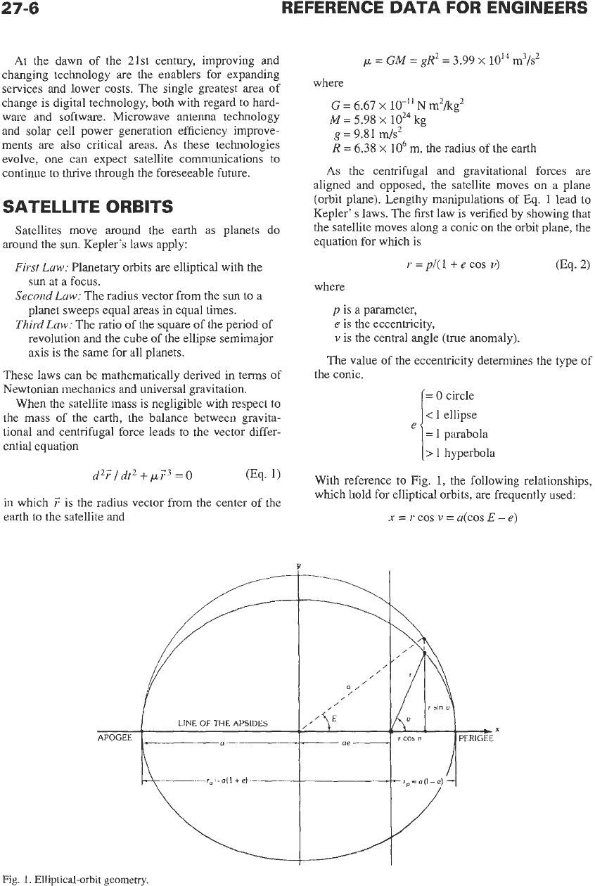
With reference
to
Fig. 1, the following relationships,
which hold for elliptical orbits, are frequently used:
x
=
rcos v=a(cosE-e)
LINE
OF
THE
APSIDES
---
APOGEE
io
=
o(l
+e)
___
Fig.
1.
Elliptical-orbit
geometry.
27-7
y
=
r
sin
v
=
a
sin
E
(1
-
e2j1I2
Eccentricity:
e
=
cia
=
(r,
-
rp)/(r,
+
rp)
Semimajor axis:
a
=
(r,
+
rp)/2
Apogee distance:
r,
=
a
+
c
=
a(1
+
e)
Perigee distance:
rp
=
a
-c
=
a(1
-e)
Locus parameter:
p
=
a(1-
e')
=
2ra
rp
/(ra
+
rp)
Semiminor axis:
b
=
a(1-
=
(r,
rp)112
Kepler's second and third laws can be derived from
Eq.
1
through manipulations based
on
conservation of
energy and angular momentum considerations whereby
212
-
p/2
=
constant
(Eq.
3)
and
-
r'xv'=h
(Eq.
4)
(Eq.
5)
The orbit period,
P,
is then
3/2
112
P=25-a
/p
Angle
E
(eccentric anomaly) is the central angle mea-
sured from the
x
axis to the vertical projection of the
satellite point over the circle of radius
a.
The true
anomaly,
v,
and the eccentric anomaly,
E,
are related
by any of the expressions:
cos
E
=
(e
+
cos v)/(l
+
e
cos
v)
cos
v
=
(e
-
cos
E)/(e
cos E
-
1)
tan
(v/2)
=
[(I
+
e)/(l-
tan
(ED)
For the hypothetical case of uniform motion on the
circle circumscribing the ellipse, where
t
=
time, the
fictitious angle
M
(mean anomaly) can be defined as
M
=
2T tip
(Eq.
6)
(Eq.
7)
0%.
8)
Angles
M
and
E
are related by the equation
M
=
E
-
e sin E
v2
=
2p/r
-
p/a
It can also be shown that
and that the orbit velocity vector has two constant
components respectively normal
to
the radius vector
and the major axis of the ellipse.
To
define the satellite position in inertial space,
three additional angles are required. These are: the
inclination,
i,
of the orbit plane with respect to the
equatorial plane of the earth; the right ascension
(longitude),
0,
of the ascending node [i.e., the angle
between the direction,
y,
of the vernal equinox (point
of Aries) and the intersection of the orbit and equato-
rial planes]; and finally the argument of perigee,
w,
i.e., the angle measured in the orbit plane between
the direction of the ascending node and that of the
perigee.
The nonsphericity of the earth, the nonuniform dis-
tribution of its mass, as well as the effects of lunar and
solar gravitation make the actual motion of satellites
depart from that described
so
far, which is based
on
the
simple two-body problem.
The gravitational potential of the earth, which is
no
longer simply proportional to the inverse of the dis-
tance, can be expressed as a series of spherical func-
tions. Two motions known as
secular variations
result
from the above-mentioned causes; these are nodal
regression and rotation of the line of the apsides.
Nodal regression is a rotation of the orbit plane
in
the direction opposite to the satellite motion around
the axis of rotation of the earth. The rate of this motion
(in degrees per day) is
Rotation of the line of the apsides is rotation of the
ellipse major axis around the center of the earth
on
a
fixed orbit plane. Apogee and perigee move then with
respect to the earth, and the rate of motion of the argu-
ment of perigee is
also
a function of the orbit inclina-
tion angle,
i,
or:
&
=
[5/(1
-
e2)2](R/a)712
(5
cos2
i
-
l)"/day
(Eq.
10)
The critical value
i
=
cos
(l/&)
=
63"24'
stops this
motion. Smaller values of
i
make the ellipse rotate in
the same sense as the satellite motion along it; higher
values of
i
make the ellipse rotate in the opposite
sense. The effect becomes smaller for higher orbits.
Gravitational forces due to the moon and the
sun
also influence satellite motion. For low-altitude orbits,
the gravitational field of the earth is preponderant and
solar and lunar effects can be neglected. For high-alti-
tude orbits, gravitational disturbances of the moon and
the
sun
cannot be neglected.
In
the case of a geosta-
tionary orbit, the sun and
moon
perturbation forces,
respectively, amount
to
about
1/37
and
1/6000
of the
gravitational force of the earth. The combined effect
would change the orbital inclination
of
a satellite orig-
inally placed
in
a perfectly equatorial orbit by about
1
degree per year.
INFORMATION
TRANSMISSION
IN
SPACE
In
a link between two points
in
space,
A
and B, sep-
arated by the distance
r,
a transmitter located at
A
of
27-8
REFERENCE
DATA
FOR ENGINEERS
power
P,,
radiated by an antenna having a gain
G,,
pro-
duces at point B a power flux density
4
=
P, Gll(4m?-)
(Eq.
11)
A
receiving antenna of effective aperture
A,.
at
B
inter-
cepts a signal power
Pr=P,GlA,.l(4~?)
(Eq.
1-21
which equals the product of the rate of information
transmission,
R,
and the energy,
E,
required
to
transmit
one bit
of
information, whence
R
=
BP, GtA,I(4rPN?)
(Eq.
13)
where
p
is the ratio of the energy required to transmit
one bit of information and the noise power density
(i.e.,
p
=
E/N,
and
No
=
N/B
where
N
is
the noise
power in bandwidth B). This parameter, which is a
function of the ratio of the channel bandwidth,
B,
and
the information rate,
R,
characterizes the efficiency of
modulation-demodulation schemes.
Equation
13
was derived by assuming an antenna of
given gain at one end of the link and an antenna of
given aperture at the other. In this case, frequency, or
wavelength, does not appear explicitly
in
the equation,
although the noise power density,
No,
is in general fre-
quency dependent.
By assuming antennas of given gain at both ends,
and using the well-known relationship
A,
=
(A2/47r)G
where
A,
=
effective aperture, the following result is
obtained:
R
=
(A2/16d) [(BP,
G,
GrI(PN?)]
(Eq.
14)
In
contrast, assuming antennas of given aperture at
both ends of the link yields
R
=
BP,A,A,.I(A*pN?)
(Eq.
15)
The above equations allow the information transmis-
sion rate,
R,
of a single space communications link to
be computed. Since the noise encountered in space
may be regarded as Gaussian, white, and additive, the
Shannon model yields
an
upper bound on transmission
rate. Equation
13
can be rewritten as
R
=
BP,G,A,.l(4m2PN)
=
(B/p)
.
(P,.lN)
(Eq.
16)
The two factors on the right-hand side relate to the two
cases of bandwidth- and power-limited transmission.
The lower bound
of
parameter
/3
=
E/N,
has the
value log,
2
=
0.693
in the limiting case of infinite
bandwidth and ideal (Shannon) modulation-demodu-
lation processes. Then the signal-to-noise ratio goes to
zero, and the information rate takes the value
lim
R
=
1.44
e.
/
N,
B+-
In
physical systems, limited bandwidth and depar-
ture from ideal modulation-demodulation processes
require higher values
of
ENo
and
P,./N.
The ratio
of
the actual information transmission rate and channel
capacity (in the Shannon sense) becomes smaller than
unity, and compromises amongst signal-to-noise ratio,
bandwidth-to-information transmission rate ratio, and
message error probabilities (or signal quality in analog
systems) must be made.
THE CHOICE
OF
THE ORBIT
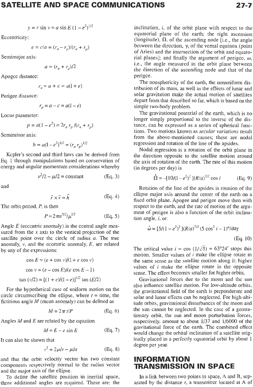
The orbit height influences the communications
range, the transmission delay, and the duration of the
connection, which is determined by the time interval
between satellite rise and set for points on the surface
of the earth separated by a given angle measured from
the center of the earth. The actual coverage is also a
function of the minimum elevation angle of earth-
station antennas. With reference to Fig.
2,
the follow-
ing relationship can be used to compute the coverage
angle:
R/(R
+
h)
=
COS
(p
+
@/COS
I9
(Eq.
18)
where
R
=
earth radius
h
=
orbit height
p
=
coverage angle
0
=
elevation angle
The transmission delay can reach a maximum
ta
=
[2
(R
+
h)/c](sin
p/cos 0)
(Eq.
19)
\\
Fig.
2.
Coverage
and
elevation
angles.
SATELLITE AND SPACE COMMUNICATIONS
27-9
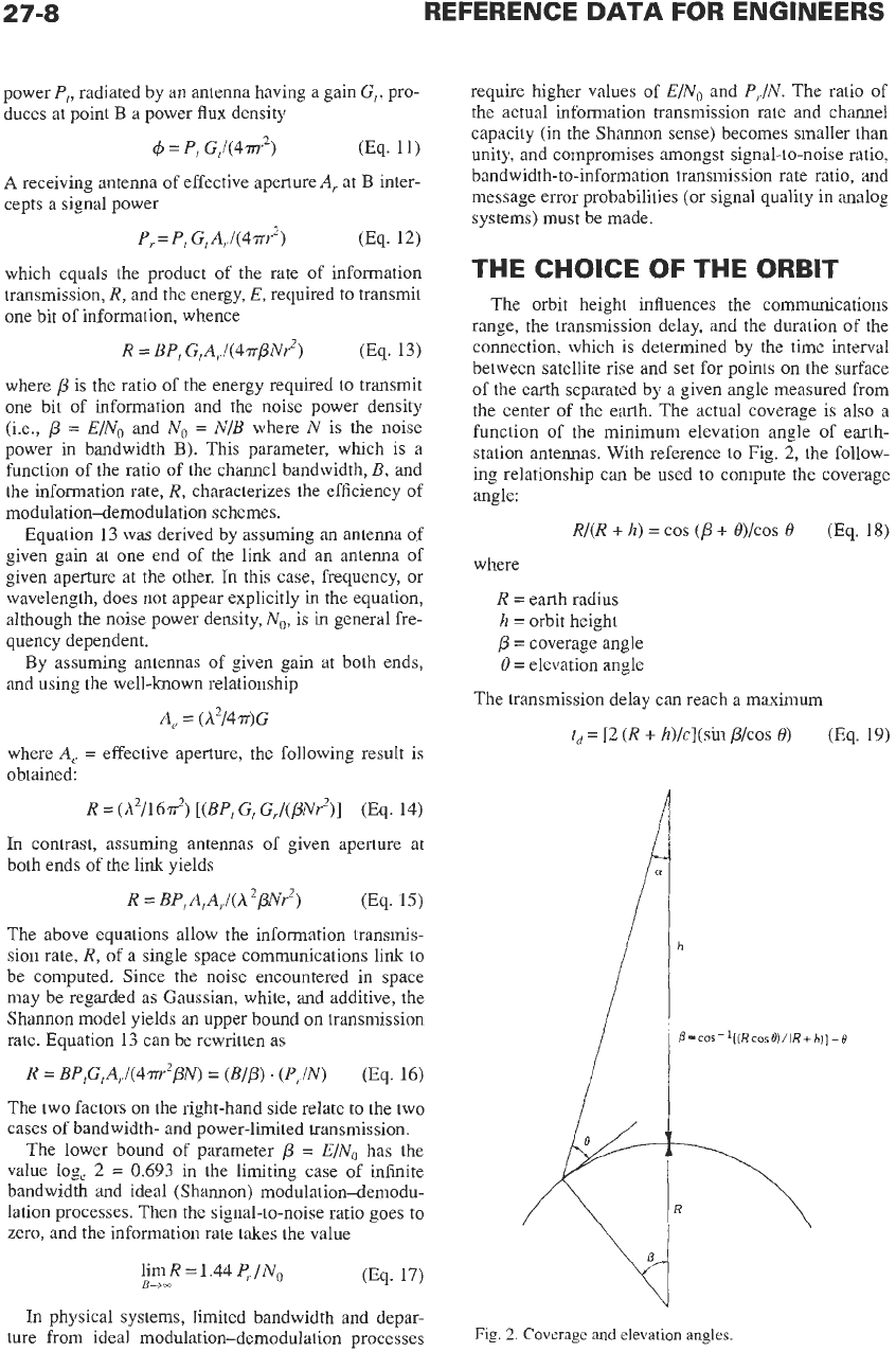
Curves for the period,
P,
the earth coverage, and the
maximum transmission delay,
ta,
are
shown in Fig.
3
for circular orbits.
Satellite systems can be classified in terms of the
inclination angle,
i,
between the orbit plane and the
equatorial plane:
i
=
90°,
i.e., polar orbits
0
<
i
<
90°,
Le., inclined orbits
i
=
0,
i.e., equatorial orbits
If the orbit is circular and the orbital height is
35.863
x
lo6
meters, the period equals a sidereal day
(23
hr
56
min
4
s),
and if the orbital plane coincides with that of
the equator of the earth, the satellite becomes geosta-
tionary.
In
the absence of perturbations, such satellites
hover over fixed points of the equator and subtend the
earth with an angle of
17’27’.
Communications can
thus be established between any two points “visible”
from the satellite over an area that amounts to about
40%
of the entire surface of the earth. In this case, the
handover problem, i.e., the passing
of
traffic from one
satellite to another. which would be necessary with
nonstationary satellites, is avoided. Other significant
advantages are simplification
of
tracking by earth sta-
tions and near-zero Doppler effects.
The transmission delay, which ranges from
0.238
to
0.275
second for single-hop circuits, has been found
acceptable for telephone communications provided
that the echo at times generated in terrestrial telephone
plants at the transition points between four- and two-
wire circuits is kept under control. This has been done
by using echo cancellers.
SOLAR ECLIPSES
A
satellite is illuminated by the sun continuously
except for the periods during which it is shadowed by
the earth.
As
a spacecraft enters the shadow of the
earth, the supply of electrical energy derived from
solar-cell panels is cut
off,
and a substantial drop in the
25
2
20
5
15
n
s?
3
10
2
P
5
0
103
104
ORBITAL HEIGHT
IN
KILOMETERS
temperature
of
the spacecraft body occurs; reversal of
these phenomena takes place when the satellite comes
out of the shadowed region.
In
the case of communica-
tions satellites, where continuity
of
service is needed
during eclipses, it is clear that some alternate source of
electrical energy must be provided. Storage batteries,
usually of the Ni-Cd or Ni-H, type currently, provide
this energy, being charged by a fraction of the energy
obtained by sunlit solar-cell panels and discharged
during eclipse periods. With regard to thermal effects,
great care must be exercised in the construction of all
spacecraft subsystems
so
that all functions are prop-
erly maintained, notwithstanding the large temperature
excursions encountered.
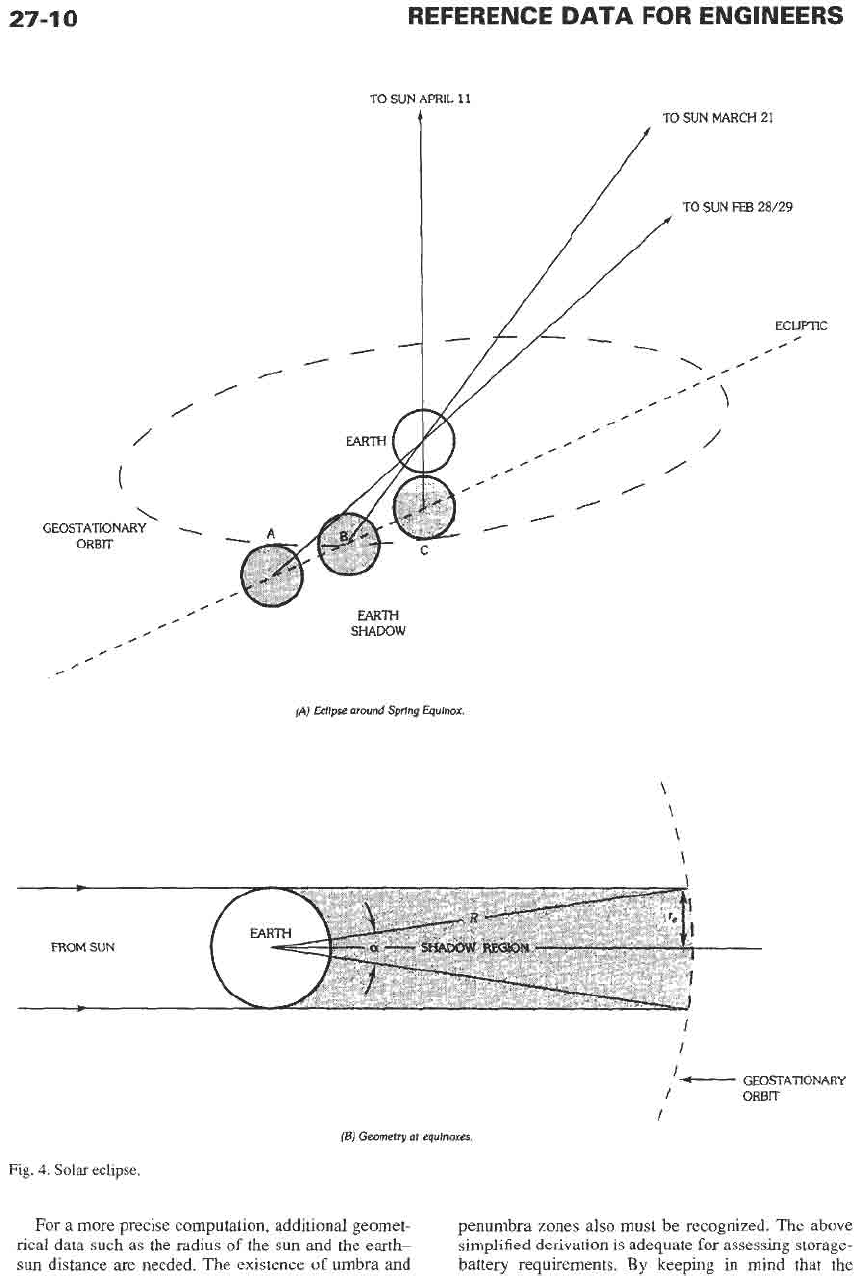
Eclipses have known onset times and duration; i.e.,
they are highly predictable events calculated from
ephemeris data. Although such calculations tend to be
complex for satellites orbiting the earth at different
altitudes and inclinations, they become fairly simple
for satellites whose orbits lie in the equatorial plane of
the earth, such as geostationary satellites. For this case,
solar eclipses occur around the spring and autumn
equinoxes. Fig.
4A
illustrates what happens around the
spring (vernal) equinox: Shadowing of the satellite
begins at point
A
when it becomes positioned tangen-
tially
to
the shadowed area. This occurs at the end
of
February. Subsequently, the duration
of
the eclipse
increases until the spacecraft finds itself at point B on
the equinox day (March
21),
which yields an eclipse of
maximum duration. After
this,
the eclipse phenome-
non continues with decreased duration until point
C
(April
1
l),
when the satellite position is again tangen-
tial to the shadow of the earth. The situation repeats
itself from September
12
to
October
14
around the
autumnal equinox (September
23),
at which date the
eclipse duration hits a maximum again.
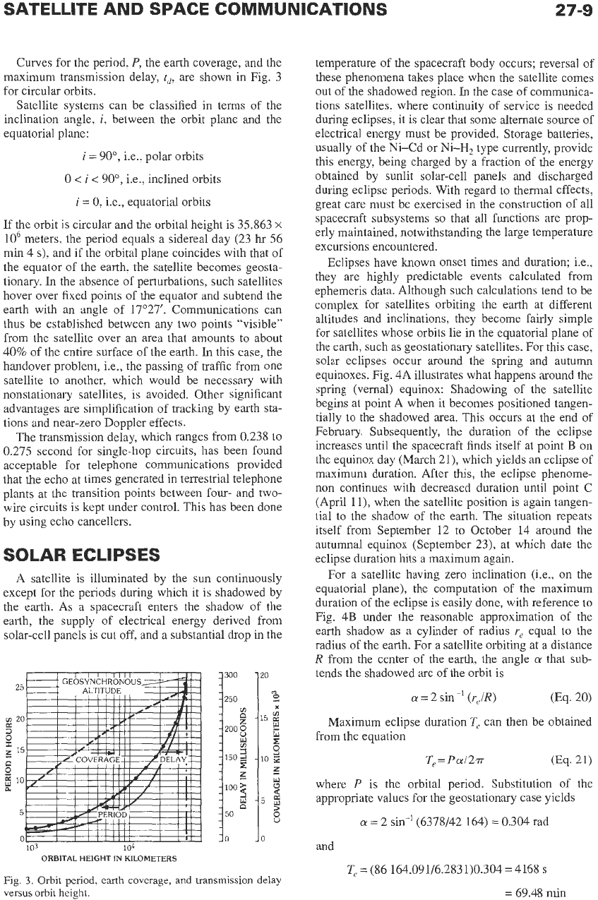
For a satellite having zero inclination (ie., on the
equatorial plane), the computation of the maximum
duration of the eclipse is easily done, with reference to
Fig.
4B
under the reasonable approximation
of
the
earth shadow as a cylinder of radius
re
equal
to
the
radius
of
the earth. For a satellite orbiting at a distance
R from the center of the earth, the angle
a
that sub-
tends the shadowed arc
of
the orbit is
a
=
2
sin
(r,/R)
(Eq.
20)
Maximum eclipse duration
T,
can then be obtained
from the equation
T,=
Pal2rr
(Eq.
21)
where
P
is the orbital period. Substitution of the
appropriate values for the geostationary case yields
a
=
2
sin-’
(6378/42 164)
=
0.304
rad
and
T,
=
(86 164.091/6.2831)0.304
=
4168
s
=
69.48
min
Fig.
3.
Orbit period,
earth
coverage, and transmission delay
versus orbit height.
27-1
0
/
/
\
GEOSTATIONARY
.
ORBlT
0
/
,
.
r
.
0
0
r
0
,
REFERENCE
DATA
FOR
ENGINEERS
TO SUN APRIL
11
t
TO
SUN
MARCH
21
/
SHAWW
(A)
Eclipse
around
Sprlng
Equinox
\
\
\
\
FROM
SUN
(5)
Geometry
at
equlnoxes.
Fig.
4.
Solar
eclipse.
I
I
'-
GEOSTATlONARY
I
ORBIT
1
For
a
more precise computation, additional geomet-
rical data such as the radius of the
sun
and the earth-
sun
distance are needed. The existence
of
umbra and
penumbra zones
also
must
be recognized. The above
simplified derivation is adequate
for
assessing storage-
battery requirements.
By
keeping
in
mind that the
SATELLITE AND SPACE COMMUNICATIONS
maximum eclipse duration at each of the equinoxes is
about
80
minutes and adding the lesser contributions
during the entire eclipse periods, it is found that the
total time of darkness amounts to about
3
hours/year.
NONGEOSTATIONARY ORBITS
Since the necessary rockets and know-how related
to the complex in-orbit injection maneuvers were
developed, the majority of commercial communica-
tions
satellites were of the geostationary type until the
1990s.
However, because the elevation angle at an
earth station drops at higher latitudes, geostationary
satellites cannot serve the near-polar regions. For this
purpose, other orbits have been used. Polar orbits are
also used for non-communications-type missions such
as earth observations, weather, surveillance, etc.
From Eq.
19,
the maximum latitude that can be
served
is
/3
=
COS-’
[(R
COS
8)/(R
+
h)]
-
8
(Eq. 22)
Hence, for a minimum elevation angle
8
of
5”,
p
=
76’21’. Thus, inclined orbits are required to serve
those regions further north.
On
the basis of energy
considerations, it can be shown that for
a
given rocket,
the lower the perigee the higher the apogee. The
slower satellite motion around apogee results in the
dual benefit of making communications possible over
greater distances
on
earth and for longer periods of
mutual visibility; the tracking problems
are
also
eased.
As
previously mentioned, an orbit inclination
of
63.5” is advantageous because of the zero rotation of
the line of the apsides for this critical angle. The
inclined orbit discussed above, 63.5” inclination,
12-
hour period, turns out to be highly advantageous. A
satellite in such an orbit spends about
8
hours near
geosynchronous altitude. Thus three such satellites can
provide continuous service at altitude. Further, prop-
erly adjusted, the satellites return to the same station
every 24 hours. Finally, because of the inclination, at
altitude the satellites can be seen
in
polar regions. The
former USSR (and the current Russia) had extensive
polar regions and used the
MOLNIYA
series of satel-
lites in the above-mentioned inclined orbit to provide
point-to-point telephony (fixed satellite services), data
relay, mobile communications, TV distribution, and
DBS
services very successfully. Variants of this orbit
will
be
used in the United States
(for
DARS)
and in
Japan (for multimedia).
Advances in technology permitting high levels of
sophistication
on
board smaller satellites have led to
a
variety of proposals for constellations
of
satellites in
low earth orbit (LEO) and in medium earth orbit
(MEO)
to provide mobile or data relay, remote sens-
ing, radio location services, or combinations thereof.
Some, such as data relay satellites
(TDRSS),
radioloca-
tion
(LOCSTAR),
mobile communications
(Iridium,
Globalstar,
and others) and messaging/paging
(ORB-
27-1
1
COMM)
are in service (in all or in part) and others,
such as
KO,
are actively under construction at the date
of publication
of
this book. The basic reason that these
systems have emerged in the
1990s
is that the cost of
the technology required and the reliability of the com-
ponents (largely digital), combined with their reduced
weight and power requirements (of VLSICS), have
made such systems practical to build, launch, and
maintain in orbit.
Because
of
the van Allen belts with their much
higher radiation levels, which significantly and delete-
riously affect the satellite electronics, the choice of
orbits is limited. LEOS lie below the inner van Allen
belt; MEOs lie between them and
GEOs
above them.
The LEO systems have certain advantages. They
have much shorter earth-satellite paths, which leads to
lower eirp requirements and much shorter delays. Fur-
ther, especially
of
advantage
in
mobile/urban commu-
nications, elevation angles to the useful part of the
LEO are high, thus making for less “multipath.” How-
ever, their lower orbits require sizable constellations of
satellites for continuous service (e.g., 66 for
Iridium).
ME0
systems are,
as
might be expected, intermedi-
ate
in
their delay and their eirp requirements, and their
constellations are smaller. The trade-offs made in sys-
tem design determine the altitude and inclination of
the orbits and the
rf
frequency/elevation angle/avail-
ability considerations combine
to
define the constella-
tions.
(GEO
systems are well known and amply
described herein.)
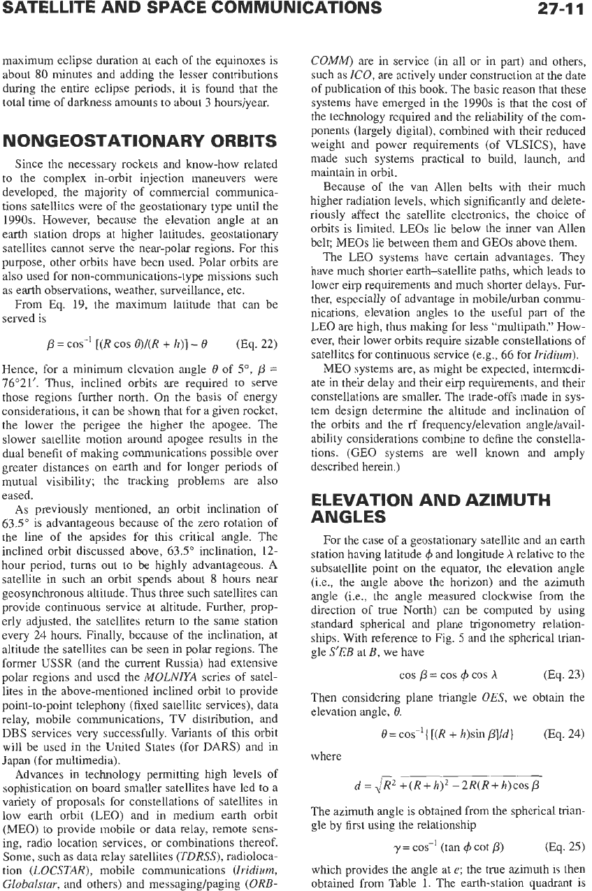
ELEVATION AND AZIMUTH
ANGLES
For the case of a geostationary satellite and an earth
station having latitude
4
and longitude
A
relative to the
subsatellite point
on
the equator, the elevation angle
(i.e., the angle above the horizon) and the azimuth
angle (i.e., the angle measured clockwise from the
direction of true North) can be computed by using
standard spherical and plane trigonometry relation-
ships. With reference to Fig. 5 and the spherical trian-
gle
S’EB
at
B,
we have
cos
p
=
cos
($
cos
h
(Eq. 23)
Then considering plane triangle
OES,
we obtain the
elevation angle,
8.
8
=
cos-’{
[(R
+
h)sin
p]/d}
(Eq. 24)
where
d
=dRz
+(R+JZ)~
-2R(R+h)cosP
The azimuth angle is obtained from the spherical trian-
gle by first using the relationship
y
=
cos-’ (tan
($
cot
p)
0%.
25)
which provides the angle at
e;
the true azimuth is then
obtained from Table 1.
The
earth-station quadrant is
27-1
2
REFERENCE
DATA
FOR ENGINEERS
T‘
S
Fig.
5.
Geometry
of
elevation and azimuth angles.
TABLE
1. TRUE AZIMUTH
RELATIONSHIPS
True
Azimuth Earth-Station Quadrant
180
-
7
Nw
Y
sw
180+
y
NE
360
-
y
SE
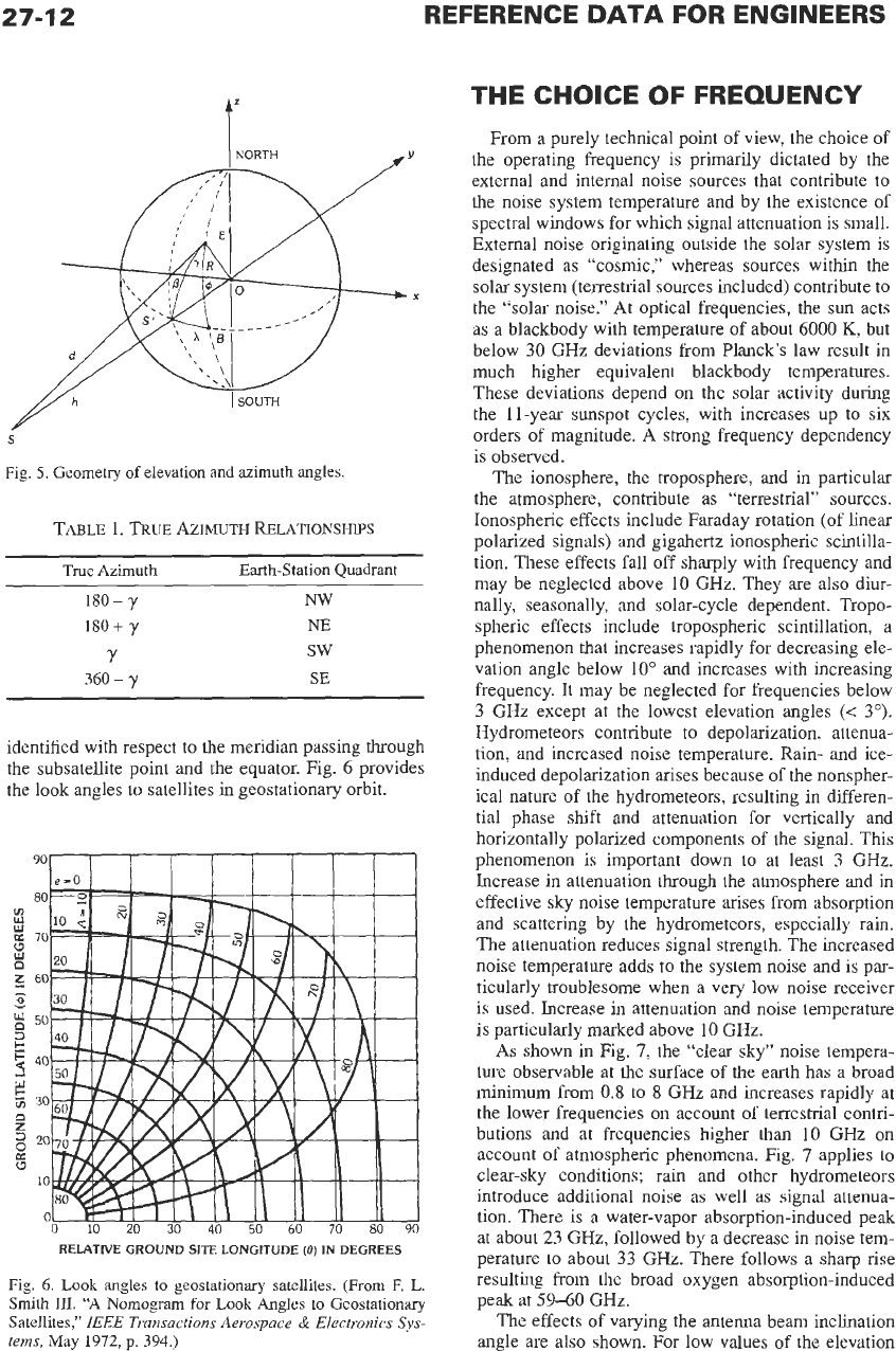
identified with respect to
the
meridian passing through
the subsatellite point and the equator. Fig. 6 provides
the look angles to satellites
in
geostationary orbit.
I
I I
I
I
I
I
I
RELATIVE GROUND SITE
LONGITUDE
(8)
IN
DEGREES
Fig.
6. Look
angles to geostationary satellites. (From F.
L.
Smith
111.
“A
Nomogram for
Look
Angles to Geostationary
Satellites,”
IEEE
Transactions Aerospace
&
Electronics
Sys-
tems,
May
1912,
p.
394.)
THE CHOICE OF FREQUENCY
From a purely technical point of view, the choice of
the operating frequency is primarily dictated by the
external and internal noise sources that contribute to
the noise system temperature and by the existence of
spectral windows for which signal attenuation is small.
External noise originating outside the solar system is
designated as “cosmic,” whereas sources within the
solar system (terrestrial sources included) contribute to
the “solar noise.” At optical frequencies,
the
sun
acts
as a blackbody with temperature of about 6000
K,
but
below
30
GHz deviations from Planck’s law result in
much higher equivalent blackbody temperatures.
These deviations depend
on
the solar activity during
the 11-year sunspot cycles, with increases up to six
orders of magnitude. A strong frequency dependency
is observed.
The ionosphere, the troposphere, and in particular
the atmosphere, contribute as “terrestrial” sources.
Ionospheric effects include Faraday rotation (of linear
polarized signals) and gigahertz ionospheric scintilla-
tion. These effects fall off sharply with frequency
and
may be neglected above
10
GHz. They are also diur-
nally, seasonally, and solar-cycle dependent. Tropo-
spheric effects include tropospheric scintillation, a
phenomenon that increases rapidly for decreasing ele-
vation angle below 10” and increases with increasing
frequency. It may be neglected for frequencies below
3
GHz except at the lowest elevation angles
(<
3”).
Hydrometeors contribute to depolarization, attenua-
tion, and increased noise temperature. Rain- and ice-
induced depolarization arises because of the nonspher-
ical nature
of
the hydrometeors, resulting in differen-
tial phase shift and attenuation for vertically and
horizontally polarized components of the signal. This
phenomenon is important down to at least
3
GHz.
Increase in attenuation through the atmosphere and in
effective
sky
noise temperature arises from absorption
and scattering by the hydrometeors, especially rain.
The attenuation reduces signal strength. The increased
noise temperature adds
to
the system noise and is par-
ticularly troublesome when a very low noise receiver
is used. Increase in attenuation and noise temperature
is
particularly marked above 10 GHz.
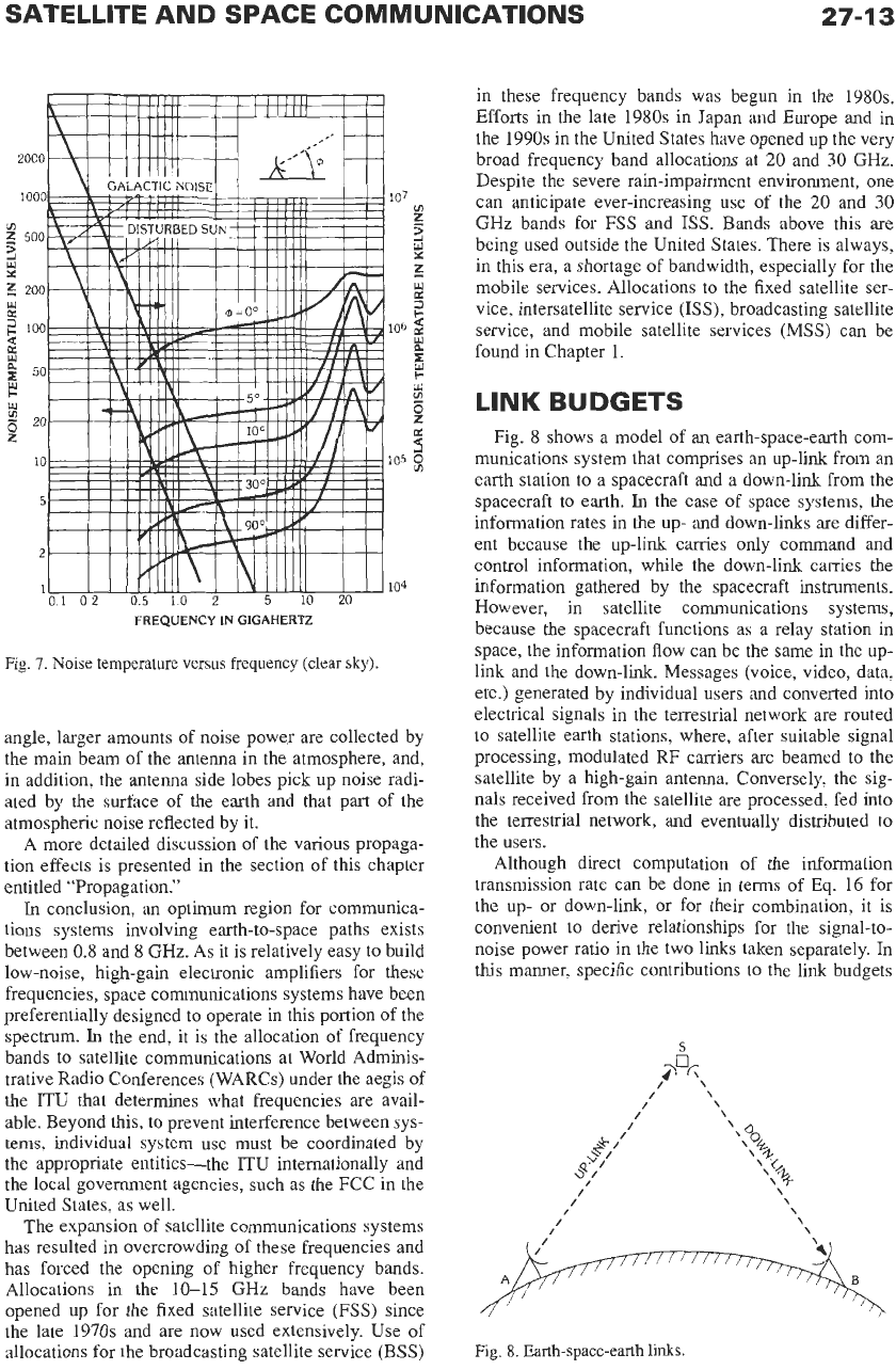
As shown in Fig.
7,
the “clear sky” noise tempera-
ture observable at
the
surface
of
the
earth
has
a
broad
minimum from 0.8 to
8
GHz and increases rapidly at
the lower frequencies
on
account
of
terrestrial contri-
butions and at frequencies higher than
10
GHz
on
account of atmospheric phenomena. Fig.
7
applies to
clear-sky conditions; rain and other hydrometeors
introduce additional noise as well as signal attenua-
tion.
There is a water-vapor absorption-induced peak
at
about
23
GHz, followed by a decrease in noise tem-
perature to about
33
GHz. There follows a sharp rise
resulting from the broad oxygen absorption-induced
peak at
59-60
GHz.
The effects
of
varying the antenna beam inclination
angle are also shown. For low values of the elevation
SATELLITE AND SPACE COMMUNICATIONS
27-1
3
Fig.
7.
Noise temperature
versus
frequency (clear
sky).
IO’
v)
2
z
x
104
angle, larger amounts of noise power are collected by
the
main
beam of the antenna in the atmosphere, and,
in addition, the antenna side lobes pick up noise radi-
ated by the surface of the earth and that part of the
atmospheric noise reflected by it.
A
more detailed discussion of the various propaga-
tion effects is presented in the section of this chapter
entitled “Propagation.”
In
conclusion,
an
optimum region for communica-
tions systems involving earth-to-space paths exists
between
0.8
and
8
GHz.
As it is relatively easy to build
low-noise, high-gain electronic amplifiers for these
frequencies, space communications systems have been
preferentially designed to operate in this portion of the
spectrum.
In
the end, it is the allocation of frequency
bands to satellite communications at World Adminis-
trative Radio Conferences (WARCs) under the aegis
of
the ITU that determines what frequencies are avail-
able. Beyond this, to prevent interference between sys-
tems, individual system use must be coordinated by
the appropriate entities-the
ITU
internationally and
the local government agencies, such as the FCC in the
United States,
as
well.
The expansion of satellite communications systems
has resulted in overcrowding of these frequencies and
has forced the opening of higher frequency bands.
Allocations in the
10-15
GHz
bands have been
opened up for the fixed satellite service (FSS) since
the late
1970s
and are now used extensively. Use of
allocations for the broadcasting satellite service
(BSS)
in these frequency bands was begun in the
1980s.
Efforts in the late
1980s
in Japan and Europe and in
the
1990s
in the United States have opened up the very
broad frequency band allocations at
20
and
30
GHz.
Despite the severe rain-impairment environment, one
can anticipate ever-increasing use of the
20
and
30
GHz
bands for
FSS
and
ISS.
Bands above this are
being used outside the United States. There is always,
in this era, a shortage of bandwidth, especially for the
mobile services. Allocations to the fixed satellite ser-
vice, intersatellite service (ISS), broadcasting satellite
service, and mobile satellite services
(MSS)
can be
found in Chapter
1.
LINK
BUDGETS
Fig.
8
shows a model of an earth-space-earth com-
munications system that comprises an up-link from an
earth station to
a
spacecraft and a down-link from
the
spacecraft to earth.
In
the case of space systems, the
information rates in the up- and down-links are differ-
ent because the up-link carries only command and
control information, while the down-link carries the
information gathered by the spacecraft instruments.
However, in satellite communications systems,
because the spacecraft functions as
a
relay station in
space, the information flow can be the same in the up-
link and the down-link. Messages (voice, video, data,
etc.) generated by individual users and converted into
electrical signals in the terrestrial network are routed
to
satellite earth stations, where, after suitable signal
processing, modulated
RF
carriers are beamed to the
satellite by
a
high-gain antenna. Conversely, the sig-
nals
received from the satellite are processed, fed into
the terrestrial network, and eventually distributed to
the users.
Although direct computation of the information
transmission rate can be done in terms of Eq.
16
for
the up- or down-link, or for their combination, it
is
convenient to derive relationships for the signal-to-
noise power ratio in the two links taken separately.
In
this
manner, specific contributions to the link budgets
Fig.
8.
Earth-space-earth links.
27-1
4
REFERENCE
DATA
FOR
ENGINEERS
can be identified.
In
a successive step, the overall signal-
to-noise power ratio is obtained by taking into account
any additional noise contributions, such as interference
or intermodulation. Finally, the number of channels
(telephone, TV, or other) is computed for specific com-
binations of multiplexing, modulation, and multiple
access techniques.
For the up-link, the power
flux
density at the satel-
lite is given by
4=PtGt/4mA~
(Eq. 26)
Then the received signal power is
where
A,,
=
effective area of the satellite receive antenna
G,,
=
gain of the satellite receive antenna
A,
=
up-link wavelength
The signal is received in the presence of thermal
noise contributed by the receiver (internal noise) and
the background (external noise). Both contributions
can be assumed Gaussian and white; hence the total
noise power density is
No
=
kT,,
where
k
=
1.38
x
J/K
is Boltzmann’s constant, and
T,
is the system tem-
perature.
Thus
the noise power in the
RF
transmission
bandwidth, B, is N
=
N$. Substitution in Eq. 27 yields
the up-link signal-to-noise power ratio:
-10
log
B
+
10 log
(G
/
T)/,
-10
log
k
(dB
Hz)
(dB/K)
(dBIHz
K)
(E~, 29)
The first term represents the earth station eirp; the sec-
ond, the “free space loss”; the third, the
RF
channel
bandwidth; the fourth, the satellite GIT ratio
(GJTJ;
and
the fifth, Boltzmann’s constant.
A
similar procedure yields the down-link budget:
and, in decibels, noting that
-
G,.
IS
.
(G
/
T)le,
Te
The numerical value of the Boltzmann’s-constant term
in Eqs. 29 and
3
1 is
10 log (1.38
x
=
-228.6 dBW/Hz
.
K
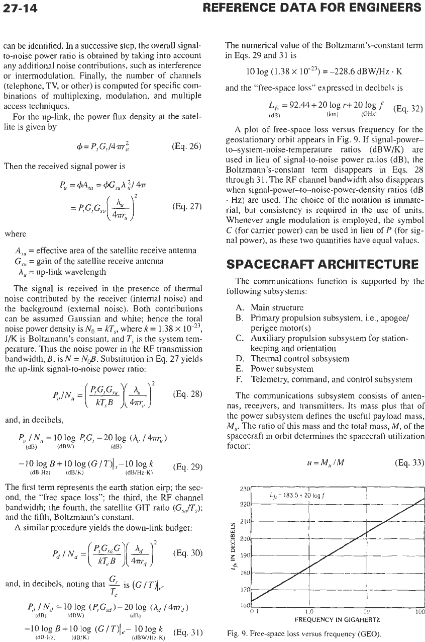
and the “free-space loss” expressed in decibels is
A plot of free-space
loss
versus frequency for the
geostationary orbit appears in Fig. 9. If signal-power-
to-system-noise-temperature ratios (dBW/K) are
used in lieu of signal-to-noise power ratios (dB), the
Boltzmann’s-constant term disappears
in
Eqs. 28
through 31. The
RF
channel bandwidth also disappears
when signal-power-to-noise-power-density ratios
(dB
.
Hz)
are used. The choice of the notation is immate-
rial, but consistency is required in the use of units.
Whenever angle modulation is employed, the symbol
C
(for carrier power) can be used in lieu of
P
(for sig-
nal power), as these two quantities have equal values.
SPACECRAFT ARCHITECTURE
The communications function is supported by the
following subsystems:
A.
Main structure
B. Primary propulsion subsystem, i.e., apogee/
perigee motor(s)
C.
Auxiliary propulsion subsystem for station-
keeping and orientation
D. Thermal control subsystem
E. Power subsystem
F.
Telemetry, command, and control subsystem
The communications subsystem consists of anten-
nas, receivers, and transmitters. Its mass plus that of
the power subsystem defines the useful payload mass,
Mu.
The ratio of
this
mass and the total mass,
M,
of the
spacecraft
in
orbit determines the spacecraft utilization
factor:
u
=
M,,
IM
(Eq. 33)
230
220
210
i
w
8
190
$
1
a0
170
160
01
10
10
100
FREQUENCY
IN
GIGAHERTZ
Fig.
9.
Free-space
loss
versus frequency
(GEO).
SATELLITE AND SPACE COMMUNICATIONS
27-1
5
Typical values
of
u
range from 0.35 to
0.60.
The differ-
ence,
Mh=M-M,=M(I-U)
(Eq.34)
represents the mass of the bus (items
A,
C,
D, and
F
of
the above-mentioned support subsystems). Finally, the
spacecraft mass at launch,
M,,
is
M,
=
M
+
Mb
0%.
35)
where
Mh
represents the mass of the primary propul-
sion subsystem.
The three satellite parameters-transmit power,
antenna gain, and bandwidth-that contribute to com-
munications capacity are proportional to the total
spacecraft mass. Designers’ efforts aim at obtaining
values
as
high
as
possible of the utilization factor
(defined by Eq. 33), and for
a
given communications
capacity, the total spacecraft mass should be kept
as
small as possible to keep launch costs down. Ever-
increasing communications capacity can be achieved
not just by constructing bigger and more powerful sat-
ellites but also by the introduction of advanced tech-
nologies in all spacecraft subsystems
as
well as in the
transmission system design.
TRANSPONDERS
Transponders are microwave repeaters carried by
communications satellites. Three possible configura-
tions are shown in Fig.
10.
The first case (Fig. 10A), in
which no signal processing takes place other than het-
erodyning from the up- to the down-link frequencies
and amplification, represents
a
class of transponders
designated as “transparent.” It can handle any signal
whose format can fit in the transponder bandwidth.
The second case (Fig.
10B)
involves switching at
rf,
and the third case (Fig. 1OC) involves switching at
base band with demultiplexing, demodulation and
remodulation, and possibly other signal processing
such
as
routing, buffering, or storage.
The receive and transmit antenna configurations
(including frequency reuse by orthogonal polarization
and/or separate beams) depend on the earth-station
topology and traffic flow. The transponder front end,
which includes filters, low-noise amplifiers, local
oscillators, mixers, and preamplifiers, is designed for
linear operation over the entire bandwidth of the up-
link
to
minimize volume, mass, and power consump-
tion of the down-converter portion
of
the transponder.
Field-effect transistors are commonly used as active
circuit elements. Distortionless transmission
is
ensured
by flat amplitude and group-delay (linear phase)
responses over the passband. Equalizers (mostly for
compensation of group delay distortion) are also used.
However, limiters are used when anti-jam protection is
needed.
Various contributions enter into the system noise
temperature.
If
the receive antenna input port is taken
as
the reference point for the configuration shown in
Fig. 11, the system noise temperature is
where
TANT
=
antenna noise temperature
Fp,
=
preamplifier noise factor
Gp,
=
preamplifier power gain
L
=
transmission line (waveguide) loss
F,
=
receiver (down-converter) noise figure
For a satellite antenna looking at the earth, the contri-
bution of the term
TAYT
is near 290
K.
Low-loss
waveguides and high-gain, low-noise preamplifiers are
clearly desirable. After the signal is converted
to
the
down-link frequency and preamplified, its level needs
to
be raised
to
the required rf power output. Redundant
receivers are used to ensure survivability over the
planned spacecraft lifetime.
The linearity requirements, which are fairly easy
to
achieve in the receiver, are difficult
to
meet in the
power amplifiers. Transmitters having output power
from
5
to 20 watts are typically used in communica-
tions satellites and in deep-space probes; hundreds of
watts will be used in satellites for direct broadcasting.
The high efficiency in the energy-conversion process
from dc to rf that is desirable for maximum utilization
of spacecraft mass and prime power conflicts with the
linearity requirements.
Traveling-wave tube amplifiers (TWTAs) domi-
nated
as
satellite high-power amplifiers (HPAs) into
the
1980s because of their wide-band, high-gain, and
high-efficiency characteristics accompanied by their
light weight, long life, and high reliability. They
remain the satellite
HPA
of choice when higher power
is needed, and
at higher frequencies (above 15 GHz).
The typical TWTA characteristics shown in Fig. 12
indicate maximum conversion efficiency at saturation
with departure from linearity. Reduction of the input
signal level yields linear, or quasilinear, operation at
lower conversion efficiency and power output.
Traveling-wave tubes also produce AM-to-PM mod-
ulation conversion effects because the phase of the
output signal is affected by the input signal amplitude.
Intermodulation noise caused by amplitude nonlinear-
ity is maximum when the TWT is driven at saturation.
Reducing the input signal amplitude yields an almost
linear operation, but the interaction of the electron
beam and the wave advancing along the helix structure
of
the tube is such that AM-to-PM conversion effects
are worst in the quasilinear region of the tube charac-
teristics.
When several modulated carriers are present at the
input, the resultant signal envelope fluctuates and pro-
duces phase variations in the output signal, resulting in
intermodulation products. Third-order intermodulation
products of the
form
V;
+
fz
-
f3)
and (2f1
-
f2)
are
T,,
290
K