Middleton W.M. (ed.) Reference Data for Engineers: Radio, Electronics, Computer and Communications
Подождите немного. Документ загружается.

27-26
REFERENCE
DATA
FOR
ENGINEERS
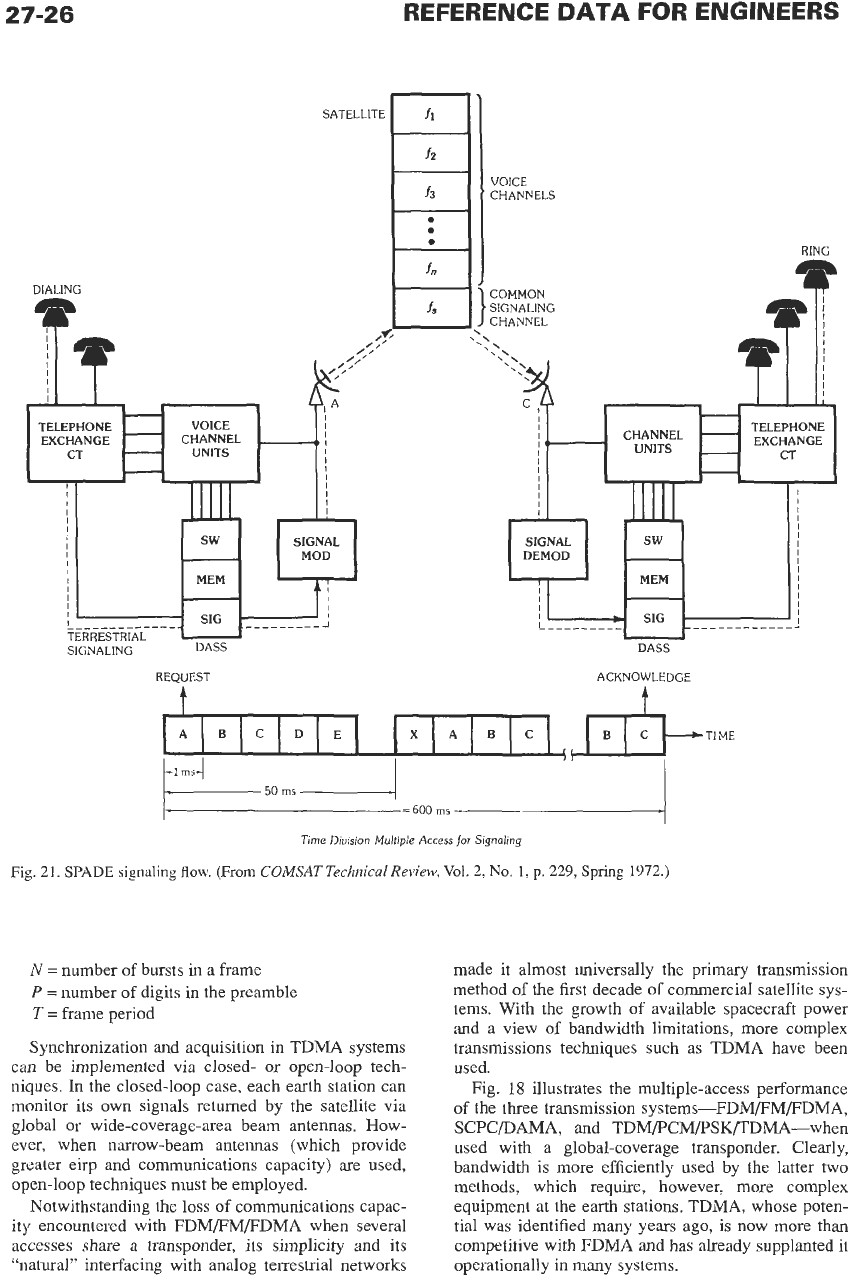
REQUEST ACKNOWLEDGE
t
I
I
dkTIME
ABCDE XABC
=
600
ms
Time
Division
Multiple
Access
for
Stgnairng
Fig.
21.
SPADE
signaling
flow, (From
COMSAT
Technical
Review,
Vol.
2,
No.
1,
p.
229,
Spring
1972.)
N
=
number of bursts in a frame
P
=
number of digits in the preamble
T
=
frame period
Synchronization and acquisition in TDMA systems
can be implemented via closed- or open-loop tech-
niques. In the closed-loop case, each earth station can
monitor its own signals returned by the satellite via
global
or
wide-coverage-area beam antennas. How-
ever, when narrow-beam antennas (which provide
greater eirp and communications capacity)
are
used,
open-loop techniques must be employed.
Notwithstanding the
loss
of
communications capac-
ity encountered with FDM/FM/FDMA when several
accesses share a transponder,
its
simplicity and its
“natural” interfacing with analog terrestrial networks
made it almost universally the
primary
hansmission
method of the first decade of commercial satellite
sys-
tems. With the growth of available spacecraft power
and a view of bandwidth limitations, more complex
transmissions techniques such as TDMA have been
used.
Fig.
18
illustrates the multiple-access performance
of the three transmission systems-FDM/FM/FDMA,
SCPCDAMA, and TDM/PCM/PSK/TDMA-when
used with a global-coverage hansponder. Clearly,
bandwidth is more efficiently used by the latter two
methods, which require, however, more complex
equipment at the earth stations. TDMA, whose poten-
tial was identified many years ago, is now more than
competitive with FDMA and has already supplanted it
operationally in many systems.
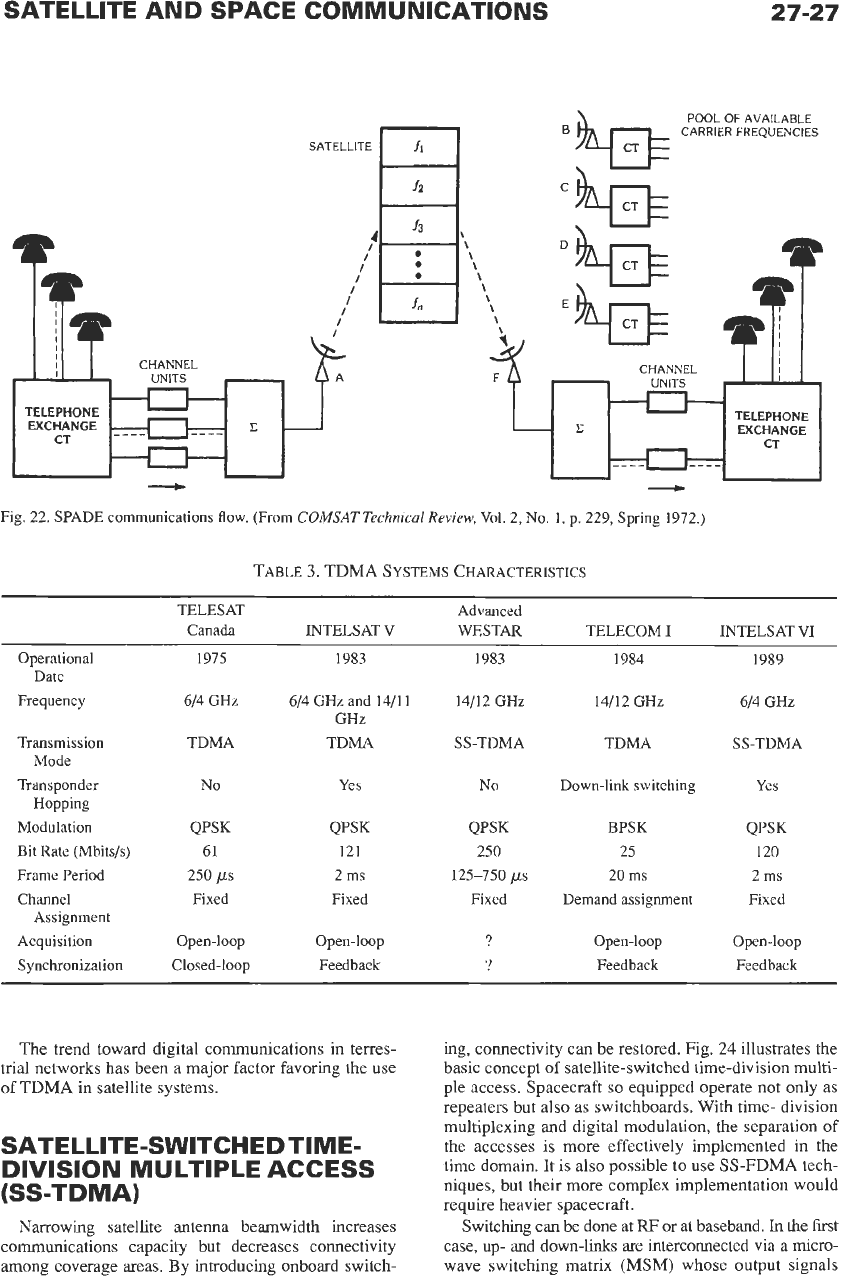
SATELLITE AND SPACE COMMUNICATIONS
27-27
POOL
OF
AVAILABLE
CARRIER FREQUENCIES
SATELLITE
I
I
I
I
I
CHANNEL
UNITS
TELEPHONE
-c
(qFEJ-(r
-
Fig.
22.
SPADE communications flow. (From
COMSAT
Technical
Review,
Vol.
2,
No.
1,
p.
229,
Spring
1972.)
TABLE
3.
TDMA
SYSTEMS
CHARACTERISTICS
TELESAT Advanced
Canada INTELSAT V WESTAR TELECOM
I
INTELSAT VI
Operational
1975 1983 1983 1984 1989
Date
Frequency
614
GHz
614
GHz and
14/11 14/12
GHz
14/12
GH2
614
GHz
GHz
SS-TDMA
Transmission TDMA TDMA
SS-TDMA TDMA
Transponder
No
Yes
No
Down-link switching
Yes
Modulation
QPSK QPSK QPSK
BPSK QPSK
Frame Period
250
ps
2
ms
125-750
ps
20
ms 2 ms
Channel Fixed Fixed Fixed Demand assignment Fixed
Acquisition Open-loop Open-loop
?
Open-loop Open-loop
Feedback Synchronization Closed-loop Feedback
?
Feedback
Mode
Hopping
Bit Rate (Mbits/s)
61 121 250 25 120
Assignment
The trend toward digital communications in terres-
trial networks has been a major factor favoring the use
of
TDMA in satellite systems.
SATE LLITE-SWITCH ED TIME-
(SS-TDMA)
DIVISION MULTIPLE ACCESS
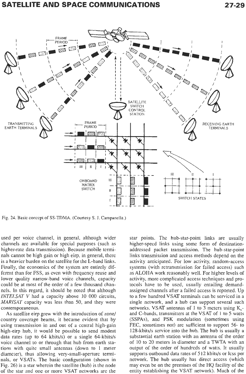
Narrowing satellite antenna beamwidth increases
communications capacity but decreases connectivity
among coverage areas.
By
introducing onboard switch-
ing, connectivity can be restored. Fig.
24
illustrates the
basic concept
of
satellite-switched time-division multi-
ple access. Spacecraft
so
equipped operate not only as
repeaters but also as switchboards. With time- division
multiplexing and digital modulation, the separation
of
the accesses is more effectively implemented in the
time domain. It is also possible to use SS-FDMA tech-
niques, but their more complex implementation would
require heavier spacecraft.
Switching can be done at
W
or
at baseband.
In
the first
case, up- and down-links are interconnected via
a
micro-
wave switching matrix
(MSM)
whose output signals
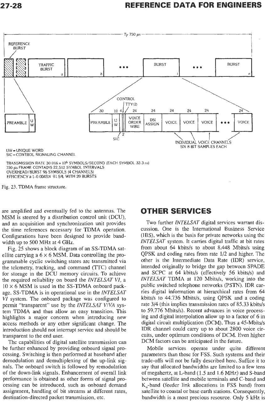
27-28
REFERENCE
DATA
FOR ENGINEERS
TRAFFIC
BURST
7,750
ps
REFERENCE
BURST
I
~
BURST
me.
BURST
...
O,“p,”p
ASSIGN
VOICE VOICE VOICE
are amplified and eventually fed
to
the antennas. The
MSM is steered by a distribution control unit (DCU),
and an acquisition and synchronization unit provides
the time references necessary for TDMA operation.
Configurations have been designed to provide band-
width up to 500 MHz at 4 GHz.
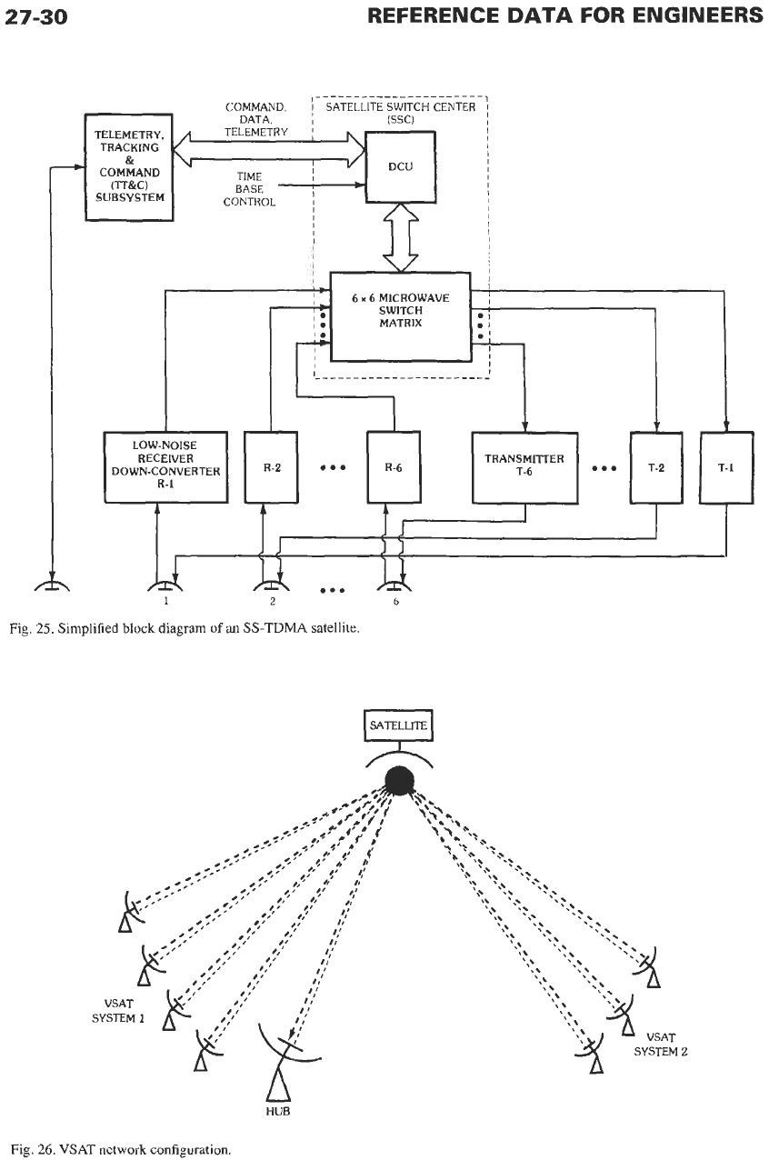
Fig.
25
shows a block diagram of an SS-TDMA sat-
ellite carrying a 6
x
6 MSM. Data controlling the pro-
grammable cyclic switching states are transmitted via
the telemetry, tracking, and command (TTC) channel
for storage in the DCU memory circuits. To achieve
the required reliability on board the
INTELSAT VI,
a
10
x
6 MSM is used in the SS-TDMA onboard pack-
age. SS-TDMA is in operational use in the
INTELSAT
VI
system. The onboard package was configured to
permit “transparent”
use
by the
INTELSAT VIVA
sys-
tem TDMA and thus allow
an
easy transition. This
highlights a major concern when introducing new
access methods or any other significant change. The
introduction should not interrupt service and should be
transparent to the end user.
The capabilities of digital satellite transmission can
be further enhanced by providing onboard signal pro-
cessing. Switching is then performed at baseband after
demodulation and demultiplexing of the up-link sig-
nals. The onboard switch is followed by remodulation
of the down-link signals. Enhancement of overall link
performance is obtained as other forms of signal pro-
cessing can be introduced, such
as
onboard demand
assignment, handling of bit streams at different rates,
destination-directed packet transmission, etc.
OTHER
SERVICES
Two further
INTELSAT
digital services warrant dis-
cussion. One is the International Business Service
(IBS), which is the basis for private networks using
the
INTELSAT
system. It carries digital traffic at bit rates
from about 64 kbits/s to about 8.448 Mbits/s using
QPSK and coding rates from rate 1/2 and higher. The
other is the Intermediate Data Rate (IDR) service,
intended originally to bridge the gap between SPADE
and SCPC at 64 kbits/s (effectively 56 kbits/s) and
INTELSAT
TDMA at
120
Mbits/s, working into the
public switched telephone networks (PSTN). IDR car-
ries digital information
at hierarchical rates from 64
kbits/s to 44.736 Mbits/s, using QPSK and
a
coding
rate 3/4 (this implies transmission rates
of
85.33 kbits/s
to
59.776 Mbits/s). Recent advances in voice process-
ing and digital interpolation allow up to
a
factor of 6 in
digital circuit multiplication (DCM).
Thus
a 45-Mbits/s
IDR
channel could carry up to about
2800
voice cir-
cuits, under optimum conditions of DCM. Even higher
DCM factors can be anticipated in the future.
Mobile services operate under quite different
parameters than those for FSS. Such systems and their
trade-offs will not be fully described here. Suffice it
to
say that allocated bandwidths are limited to a few tens
of megahertz,
at
L-band (1.5 and 1.6 MHz) and S-band
between satellite and mobile terminals and C-band and
K,-band (feeder link allocations in
FSS
band) from
satellite
to
coastal or base earth stations. Consequently,
bandwidth is
a
most precious resource. Only 5
kHz
is
SATELLITE AND SPACE COMMUNICATIONS
27-29
I
I
.?Q
I
t
\\
\',-
TRANSMITTING
EARTH TERMINALS
SATELLITE
SWITCH
CONTROL
STATION
/
RECEIVING EARTH
TERMINALS
ONBOARD
MATRIX
SWITCH
11
Fig.
24.
Basic concept
of
SS-TDMA.
(Courtesy
S.
J.
Campanella.)
used per voice channel, in general, although wider
channels are available for special purposes (such as
higher-rate data transmission). Because mobile termi-
nals cannot be high gain or high eirp, in general, there
is
a
heavier burden on the satellite for the L-band links.
Finally, the economics of the system are entirely dif-
ferent than for
FSS,
as even with frequency reuse and
lower quality narrow-band voice channels, capacity
could be at most of the order of a few thousand chan-
nels.
In
this regard, it should be noted that although
INTELSAT
V
had a capacity above
10
000
circuits,
MARISAT
capacity was less than
50,
and they were
contemporaneous.
As satellite eirp grew with the introduction of zone/
country coverage beams, it became evident that by
using transmission in and out of a central high-gain
high-eirp hub, it would be possible to send modest
data rates (up to 64 kbitsls) or a single 64-kbits/s
voice channel to or through that hub from earth sta-
tions with quite small antennas (down to
1
meter
diameter), thus allowing very-small-aperture termi-
nals, or VSATs. The basic configuration (shown in
Fig. 26) is a star wherein the satellite (hub) is the node
of
the star and one or more VSAT networks are the
star points. The hub-star-point links are usually
higher-speed links using some form of destination-
addressed packet transmission. The hub-star-point
links transmission and access methods depend on the
activity anticipated. For low activity, random-access
systems (with retransmission for failed access) such
as
ALOHA
work reasonably well. For higher levels of
activity, more complicated access techniques and pro-
tocols have to be used, usually entailing demand-
assigned channels after a failed access
is
reported. Up
to a few hundred VSAT terminals can be serviced in a
single network, and a hub can support several such
networks. VSAT antennas of
1
to
3
meters using
K,,-
and C-bands, transmitters at the VSAT of
1
to
5
watts
(SSPAs), and PSK modulation (sometimes using
FEC, sometimes not) are sufficient to support 56- to
128-kbitsls service into the hub. The hub is usually
a
substantial earth station with an antenna of the order
of
10
to
20 meters in diameter and a TWTA with an
output of the order of hundreds of watts. It usually
supports outbound data rates
of
512
kbitsls or less per
network. The hub usually has direct access (which
may even be on the premises
of
the
HQ
facility of the
entity establishing the VSAT network). Much of the
27-30
REFERENCE
DATA
FOR ENGINEERS
COMMAND,
~
SATELLITE SWITCH CENTER
ISSCI
TELEMETRY,
TRACKING
COMMAND
BASE
SUBSYSTEM
CONTROL
\
1
2
6
Fig.
25.
Simplified
block
diagram
of
an
SS-TDMA
satellite.
HUB
Fig.
26.
VSAT
network configuration.
SATELLITE AND SPACE COMMUNICATIONS
27-31
transmitted data is broadcast to the star points or
comes into the hub only. However,
using
double-hop,
the input to the hub can be retransmitted
to
another
star point.
As noted above, recent advances in satellite eirp
have permitted the introduction
of
even smaller user's
premises antennas and terminals, termed USATs in
FSS.
In
the Mobile Satellite Service
(MSS),
hand-held
terminals have begun to appear. It is expected that
Internet services will access users through these and
perhaps DBS-like terminals.
In
a sense, DBS-TV or DBSA can be considered an
extreme form
of
VSAT, where the VSATs
on
the user's
premises are truly small (down to 0.3-meter antennas)
and receive-only, and the hub station transmits the pro-
gram material to the satellite at feeder link frequency
allocations in the
FSS
to be transmitted at &-band at
very high eirps (using onboard TWTAs
of
the order of
200
watts). Of course, there are (potentially) millions
of
star points; there are
FM
as well as digital signals;
and the information rates from hub
to
star point
are
quite high
(in
the tens
of
megabits per second equiva-
lent). DBS-TV systems have long been established in
Japan, Europe, and the former USSR. Others have
been implemented in Canada, the United States, South
and Central America, and elsewhere.
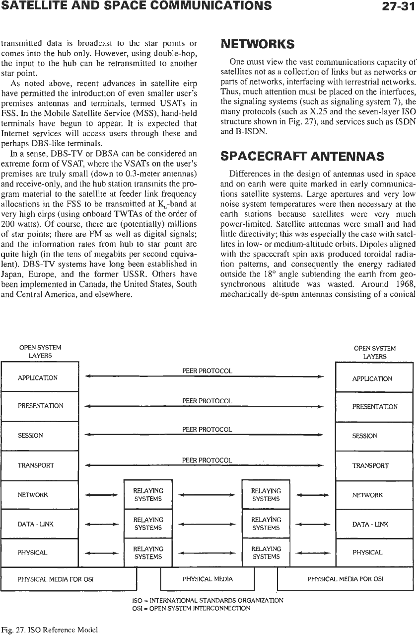
NETWORKS
One must view the vast communications capacity of
satellites not as a collection of links
but
as networks
or
parts
of
networks, interfacing with terrestrial networks.
Thus, much attention must be placed
on
the interfaces,
the signaling systems (such as signaling system
7),
the
many protocols (such as
X.25
and the seven-layer IS0
structure shown in Fig.
27),
and services such as ISDN
and B-ISDN.
SPACECRAFr ANTENNAS
Differences
in
the design
of
antennas used in space
and
on
earth were quite marked in early communica-
tions satellite systems. Large apertures and very low
noise system temperatures were then necessary at the
earth stations because satellites were very much
power-limited. Satellite antennas were small and had
little directivity; this was especially the case with satel-
lites in low- or medium-altitude orbits. Dipoles aligned
with the spacecraft spin axis produced toroidal radia-
tion patterns, and consequently the energy radiated
outside the
18"
angle subtending the earth from geo-
synchronous altitude was wasted. Around
1968,
mechanically de-spun antennas consisting
of
a conical
OPEN SYSTEM
OPEN SYSTEM
LAYERS LAYERS
PEER PROTOCOL
PEER PROTOCOL
PEER PROTOCOL
PEER PROTOCOL
-
-
-
-
PHYSICAL MEDIA PHYSICAL MEDIA FOR
OS1
I
PHYSlCAL MEDIA FOR OS1
IS0
=
INTERNATIONAL STANDARDS ORGANZATION
OS1
=
OPEN SYSTEM INTERCONNECTlON
Fig.
27.
IS0
Reference
Model.
27-32
horn and a reflector provided about 19 dB of gain (sub-
tending an angle slightly greater than
18")
at
4
and
6
GHz
(INTELSAT
HI).
Progress has continued since
then along two lines. First, large parabolic antennas
have provided spot beam coverage down to a few
degrees. Second, through frequency reuse the allocated
frequency bands are utilized many times over by
means of orthogonal polarizations (vertical/horizontal
linear or
clockwise/counterclockwise
circular) and/or
by means of spatially separated beams. Finally, zone
beams have been synthesized
to
follow the contours of
specific geographical areas such as national or regional
boundaries, continents, etc. By assembling numerous
suitably arranged feed horns, each excited with proper
amplitude and phase, the radiated energy impinges
upon a reflector and illuminates the desired areas on
earth. It should be noted that earth-coverage horns are
still used for a few C-band transponders.
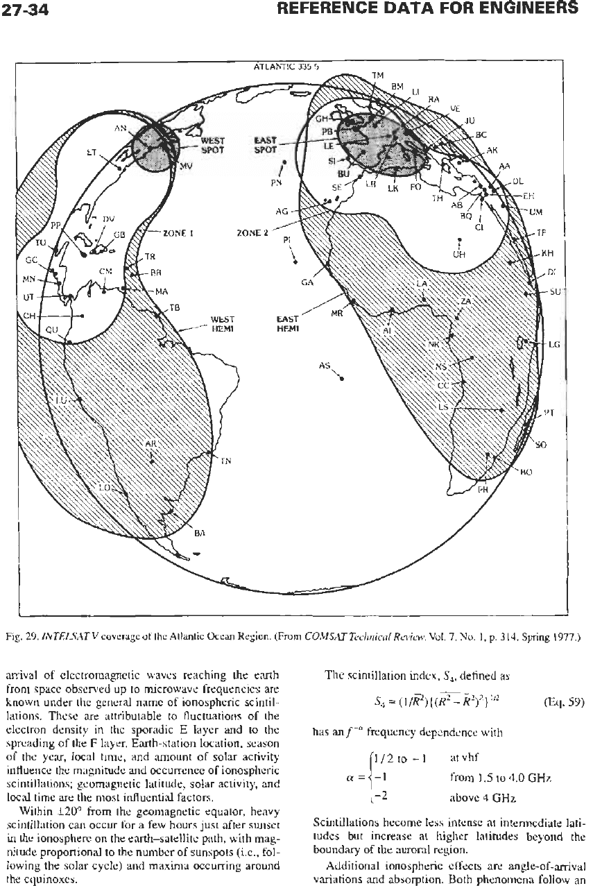
In the design of contour-shaped beams and fre-
quency-reuse systems, it is difficult to maintain isola-
tion between dually polarized and/or spatially separate
beams, especially when the number of beams is large.
Until recently, parabolic reflectors with offset feed
assemblies in the focal region have been adequate. The
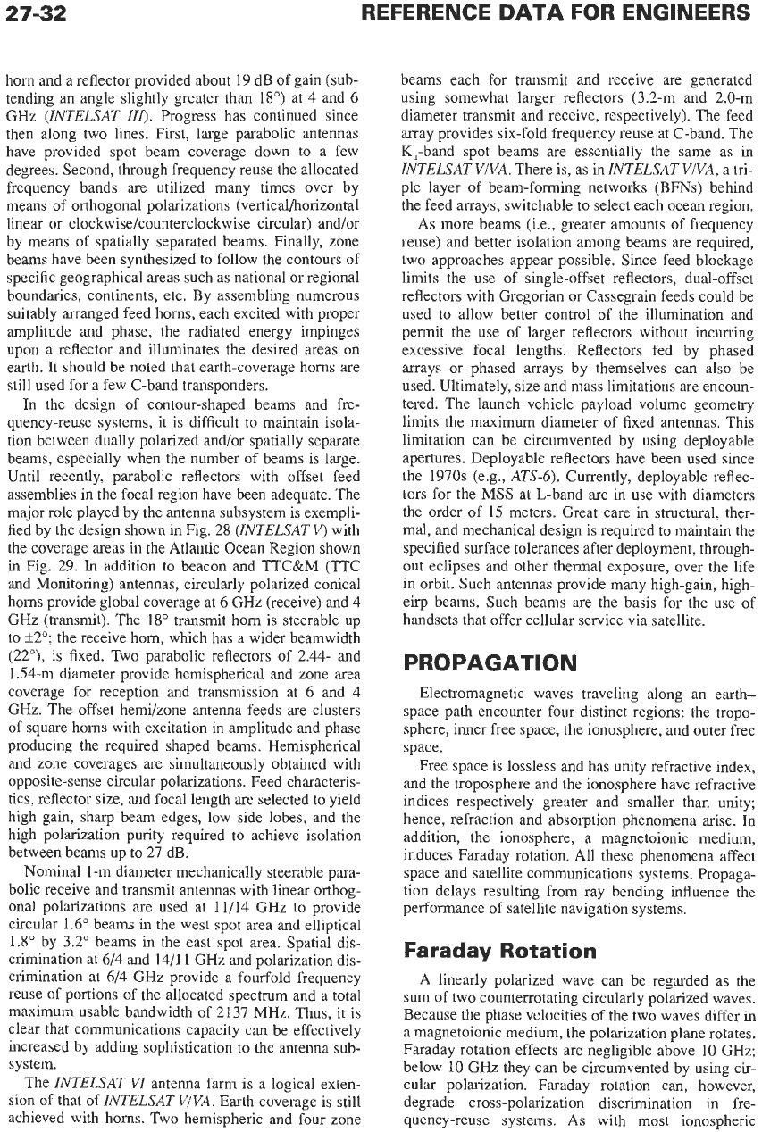
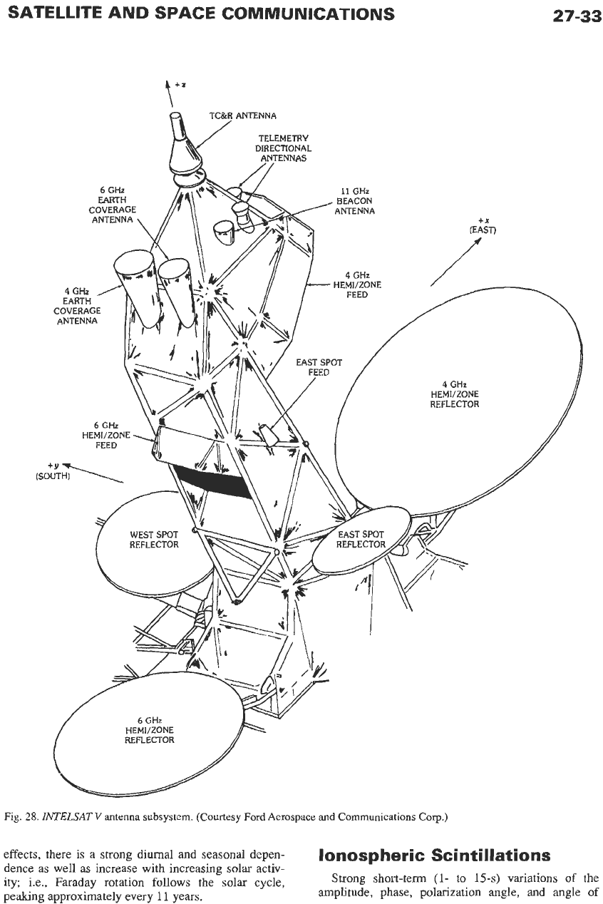
major role played by the antenna subsystem is exempli-
fied by the design shown in Fig. 28
(INTELSAT
v)
with
the coverage areas in the Atlantic Ocean Region shown
in Fig. 29.
In
addition to beacon and TTC&M (TTC
and Monitoring) antennas, circularly polarized conical
horns provide global coverage at
6
GHz (receive) and
4
GHz (transmit). The
18"
transmit horn
is
steerable up
to
f2"; the receive horn, which has a wider beamwidth
(22"), is fixed. Two parabolic reflectors of 2.44- and
1.54-m diameter provide hemispherical and zone area
coverage for reception and transmission at
6
and
4
GHz. The offset hemi/zone antenna feeds are clusters
of square horns with excitation in amplitude and phase
producing the required shaped beams. Hemispherical
and zone coverages are simultaneously obtained with
opposite-sense circular polarizations. Feed characteris-
tics, reflector size, and focal length are selected to yield
high gain, sharp beam edges, low side lobes, and the
high polarization purity required to achieve isolation
between beams up to 27 dB.
Nominal 1 -m diameter mechanically steerable para-
bolic receive and transmit antennas with linear orthog-
onal polarizations are used at 11/14 GHz
to
provide
circular 1.6" beams in the west spot area and elliptical
1.8" by 3.2" beams in the east spot area. Spatial dis-
crimination at 6/4 and 14/11 GHz and polarization dis-
crimination at 6/4 GHz provide a fourfold frequency
reuse of portions of the allocated spectrum and a total
maximum usable bandwidth of 2137 MHz. Thus, it is
clear that communications capacity can be effectively
increased by adding sophistication to the antenna sub-
system.
The
INTELSAT
VI
antenna farm is a logical exten-
sion of that of
INTELSAT VIVA.
Earth coverage is still
achieved with horns. Two hemispheric and four zone
beams each for transmit and receive are generated
using somewhat larger reflectors (3.2-m and 2.0-m
diameter transmit and receive, respectively). The feed
array provides six-fold frequency reuse at C-band. The
K,-band spot beams are essentially the same as in
INTELSAT VIVA.
There is, as in
INTELSAT VIVA,
a tri-
ple layer of beam-forming networks (BFNs) behind
the feed arrays, switchable to select each ocean region.
As more beams (Le., greater amounts of frequency
reuse) and better isolation among beams are required,
two approaches appear possible. Since feed blockage
limits the use of single-offset reflectors, dual-offset
reflectors with Gregorian or Cassegrain feeds could be
used
to
allow better control of the illumination and
permit the use of larger reflectors without incurring
excessive focal lengths. Reflectors fed by phased
arrays or phased arrays by themselves can also be
used. Ultimately, size and mass limitations are encoun-
tered. The launch vehicle payload volume geometry
limits the maximum diameter of fixed antennas. This
limitation can be circumvented by using deployable
apertures. Deployable reflectors have been used since
the 1970s (e.g.,
ATS-6).
Currently, deployable reflec-
tors for the
MSS
at L-band
are
in
use with diameters
the order of 15 meters. Great care in structural, ther-
mal, and mechanical design is required to maintain the
specified surface tolerances after deployment, through-
out eclipses and other thermal exposure, over the life
in orbit. Such antennas provide many high-gain, high-
eirp beams. Such beams are the basis for the use of
handsets that offer cellular service via satellite.
PROPAGATION
Electromagnetic waves traveling along an earth-
space path encounter four distinct regions: the tropo-
sphere, inner free space, the ionosphere, and outer free
space.
Free space is lossless and has unity refractive index,
and the troposphere and the ionosphere have refractive
indices respectively greater and smaller than unity;
hence, refraction and absorption phenomena arise. In
addition, the ionosphere, a magnetoionic medium,
induces Faraday rotation. All these phenomena affect
space and satellite communications systems. Propaga-
tion delays resulting from ray bending influence the
performance of satellite navigation systems.
Faraday Rotation
A
linearly polarized wave can be regarded as the
sum of two counterrotating circularly polarized waves.
Because the phase velocities of the two waves differ in
a magnetoionic medium, the polarization plane rotates.
Faraday rotation effects
are
negligible above
10
GHz;
below 10 GHz they can be circumvented by using cir-
cular polarization. Faraday rotation can, however,
degrade cross-polarization discrimination in fre-
quency-reuse systems.
As
with most ionospheric
SATELLITE AND SPACE COMMUNICATIONS
t'"
4
GHz
HEMVZONE
REFLECTOR
Fig.
28.
ZNTELSAT
V
antenna
subsystem.
(Courtesy
Ford
Aerospace
and
Communications COT.)
27-33
effects, there is a strong diurnal and seasonal depen-
dence as well as increase with increasing solar activ-
ity; i.e., Faraday rotation follows
the
solar cycle,
peaking approximately every
11
years.
lonospheric Scintilbtions
Strong short-term
(1-
to
15-s)
variations
of
the
amplitude, phase, polarization angle, and angle
of
27-34
REFERENCE
DATA
FOR ENGINEERS
Fig.
29.
INTELSAT
V
coverage
of
the
Atlantic Ocean Region. (From
COMSAT
Technical Review,
Vol.
7,
No.
1,
p.
314,
Spring
1977.)
arrival of electromagnetic waves reaching the earth
from space observed up to microwave frequencies are
known under the general name of ionospheric scintil-
lations. These are attributable to fluctuations
of
the
electron density in the sporadic E layer and to the
spreading of the
F
layer. Earth-station location, season
of
the year, local time, and amount of solar activity
influence the magnitude and occurrence of ionospheric
scintillations; geomagnetic latitude, solar activity, and
local time are the most influential factors.
Within
C20°
from the geomagnetic equator, heavy
scintillation can occur
for
a few hours just after sunset
in the ionosphere
on
the earth-satellite path, with mag-
nitude proportional to the number of sunspots (Le., fol-
lowing the solar cycle) and maxima occurring around
the equinoxes.
The scintillation index,
S,,
defined as
has an
f
frequency dependence with
1-2
above
4
GHz
1/2
to
-1
atvhf
a=
-1
from
1.5
to
4.0
GHz
Scintillations become less intense at intermediate lati-
tudes but increase at higher latitudes beyond the
boundary of the auroral region.
Additional ionospheric effects are angle-of-arrival
variations and absorption. Both phenomena follow an
27-35
f
law; hence, their impact on communications sys-
tems operating at gigahertz frequencies is negligible.
Tropospheric Effects
Ray bending, scintillation, attenuation, and increased
sky
noise temperature are major effects. Tropospheric
bending is opposite to ionospheric bending; it is fre-
quency independent, whereas ionospheric bending fol-
lows an
f2
law. Because the refractive index,
n,
is
slightly greater than one, the quantity
N
(refractivity)
is used
N=
(n-
1)
x
lo6
It
is empirically given as
N
=
(77.6/T)
[p
+
4810~/T]
(Eq. 60)
where
T
=
air temperature in kelvins
p
=
atmospheric pressure in millibars
E
=
partial water vapor pressure in millibars
Since
N
decreases with height, the apparent elevation
of a space object is greater than the geometrical eleva-
tion angle, and the radio range is greater than the geo-
metric distance. Eq. 60 does not hold in extremely
humid climates; ducting will occur if the vertical gra-
dient
of
N
is high. All the above phenomena are not
significant
in
the design of satellite communications
systems except for operation at very low angles of ele-
vation.
In
tropical climates, mean values of ray bend-
ing around 0.5"-0.6" have been observed at elevation
angles between
1"
and 2". Ducting can produce inter-
ference to earth-based microwave radio relays by high-
power earth stations of communications satellite sys-
tems radiating at low angles.
Scintillations are induced by atmospheric turbu-
lence with time dependence about ten times greater
than that of ionospheric scintillations. The phenome-
non
is strongly dependent on elevation angle, increas-
ing with decreasing elevation angle, and may be
neglected above 15". Between
5"
and
lo",
peak-to-
peak scintillations in excess of
6
dB have been encoun-
tered at
6
GHz.
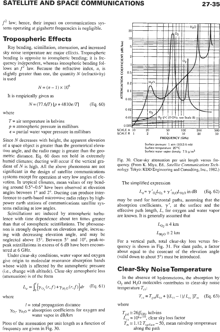
Under clear-sky conditions, water vapor and oxygen
give origin to molecular resonance absorption bands
whose width is affected by the atmospheric pressure
(Le., change with altitude). Clear-sky atmospheric loss
(attenuation)
is
of
the
form
where
1
=
total propagation distance
yo*,
yH,o
=
absorption coefficients for oxygen and
water vapor
in
dB/km
Plots of the attenuation per
unit
length as a function of
frequency are given in Fig.
30.
Surface
pressure
1
atm
(1013
6
mb)
Surface
temperature
2OOC
Surface
water
vapor
density
7
5
g/m3
Fig.
30.
Clear-sky attenuation per unit length
versus
fre-
quency.
(From
K.
Miya, Ed.,
Satellite Communications
Tech-
nology.
Tokyo:
KDD
Engineering and Consulting,
Inc.,
1982.)
The simplified expression
may be used for horizontal paths, assuming that the
absorption coefficients,
y',
at the surface and the
effective path length,
L,
for oxygen and water vapor
are
known. It is generally assumed that
Lo2z4km
L,,,
E-
2 km
For a vertical path, total clear-sky loss versus fre-
quency is shown in Fig. 31. For slant paths, a factor
about equal
to
the cosecant of the elevation angle
(valid down to about
5")
must be introduced.
Clear-Sky NoiseTemperature
In
the absence
of
hydrometeors, the absorption by
0,
and
H,O
molecules contributes
to
clear-sky noise
temperature
Tcs:
where
Tgd
2
26/fGHr kelvins
L,
=
1@nil0, clear sky loss factor
T,
1.12 Tsurface
-
50,
mean raindrop temperature
along the path