Middleton W.M. (ed.) Reference Data for Engineers: Radio, Electronics, Computer and Communications
Подождите немного. Документ загружается.

27-36
REFERENCE
DATA
FOR ENGINEERS
200
100
50
20
10
5
2
1
0.5
0.2
0.1
0.05
0.02
0
01
0
50
100
150
200
250
300
FREQUENCY
IN
GHz
Surface water vapor density
A:
7.5g/m3
8.
Ow3
(dry atmosphere]
R
is
the range
of
variation due to fine structure
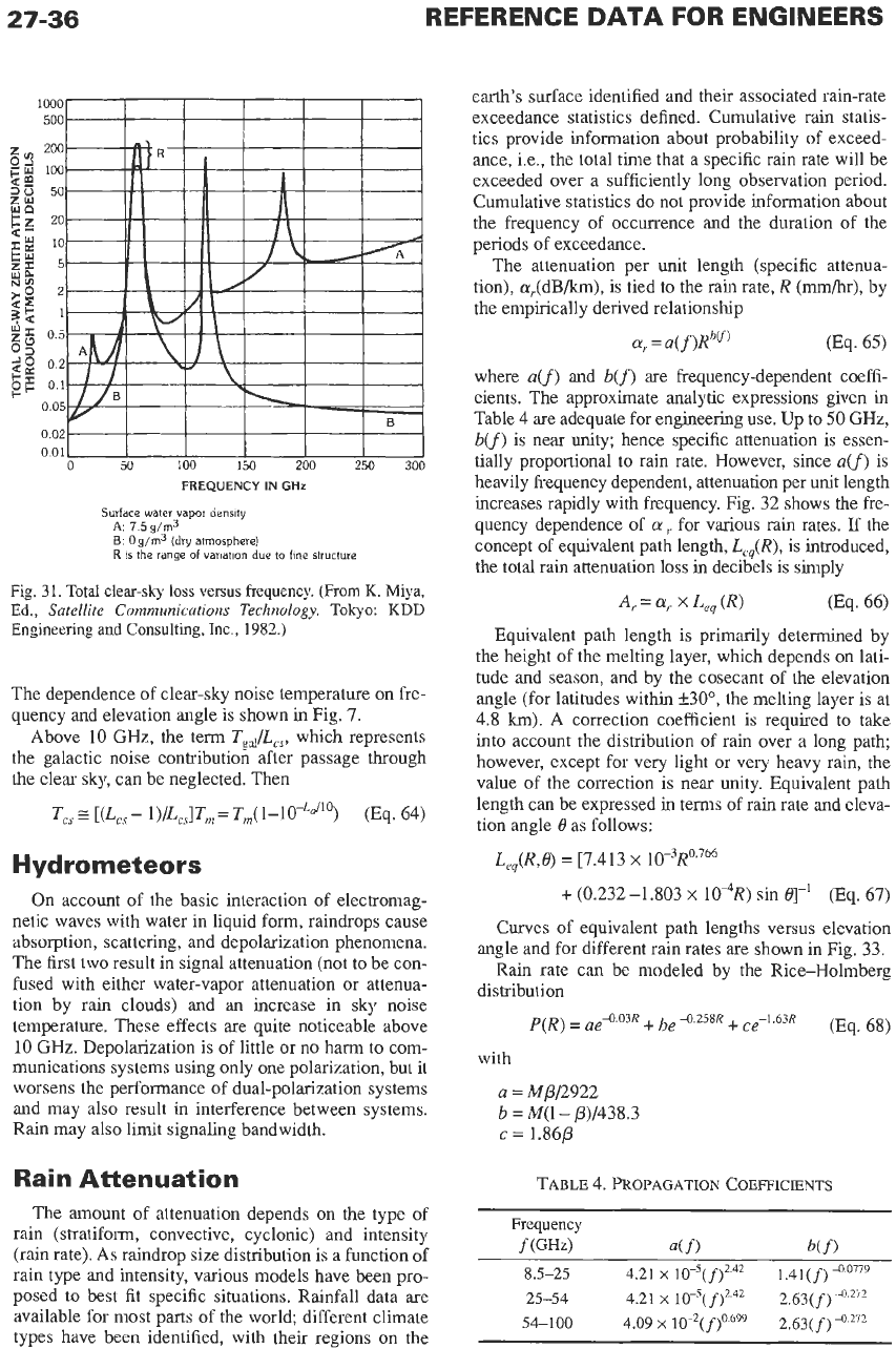
Fig.
31.
Total clear-sky loss
versus
frequency.
(From
K.
Miya,
Ed.,
Satellite Communications Technology.
Tokyo:
KDD
Engineering and Consulting, Inc.,
1982.)
The dependence of clear-sky noise temperature
on
fre-
quency and elevation angle is shown in Fig. 7.
Above
10
GHz,
the term
T,,/L,,,
which represents
the galactic noise contribution after passage through
the clear sky, can be neglected. Then
(Eq. 64)
T,,
E
[(L,,
-
l)/L,]T,,
=
Tm(l-lO-La’lo)
Hydrometeors
On account of the basic interaction of electromag-
netic waves with water in liquid form, raindrops cause
absorption, scattering, and depolarization phenomena.
The first two result in signal attenuation (not to be con-
fused with either water-vapor attenuation or attenua-
tion by rain clouds) and an increase in sky noise
temperature. These effects are quite noticeable above
10
GHz.
Depolarization is of little or no harm to com-
munications systems using only one polarization, but it
worsens the performance of dual-polarization systems
and may also result in interference between systems.
Rain may also limit signaling bandwidth.
Rain Attenuation
The amount of attenuation depends
on
the type
of
rain (stratiform, convective, cyclonic) and intensity
(rain rate). As raindrop size distribution
is
a function of
rain type and intensity, various models have been pro-
posed to best fit specific situations. Rainfall data are
available for most parts of the world; different climate
types have been identified, with their regions on the
earth’s surface identified and their associated rain-rate
exceedance statistics defined. Cumulative rain statis-
tics provide information about probability of exceed-
ance, i.e., the total time that a specific rain rate will be
exceeded over a sufficiently long observation period.
Cumulative statistics do not provide information about
the frequency of occurrence and the duration of the
periods of exceedance.
The attenuation per unit length (specific attenua-
tion),
a,(&/km),
is tied to the rain rate,
R
(mm/hr),
by
the empirically derived relationship
where
aCf)
and
b(f)
are frequency-dependent coeffi-
cients. The approximate analytic expressions given in
Table 4
are
adequate for engineering use. Up to
50
GHz,
b(f)
is near
unity;
hence specific attenuation is essen-
tially proportional to rain rate. However, since
aCf)
is
heavily frequency dependent, attenuation per unit length
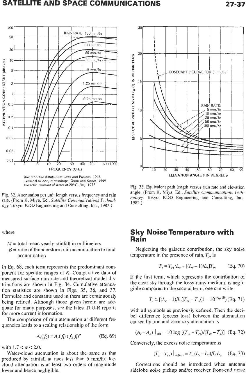
increases rapidly with frequency. Fig. 32 shows the fre-
quency dependence of
a
for various rain rates.
If
the
concept of equivalent path length,
L,,(R),
is introduced,
the total rain attenuation loss in decibels is simply
A,
=
a,.
x
Le,
(R)
Equivalent path length is primarily determined by
the height of the melting layer, which depends
on
lati-
tude and season, and by the cosecant of the elevation
angle (for latitudes within
f30”,
the melting layer is at
4.8
km).
A correction coefficient is required to take
into account the distribution of rain over a long path;
however, except for very light or very heavy rain, the
value of the correction is near unity. Equivalent path
length can be expressed in terms of rain rate and eleva-
tion angle 0 as follows:
(Eq. 66)
L,,(R,e)
=
~7.413
x
10-3~0.766
+
(0.232
-1.803
x
10%)
sin
e]-’
(Eq. 67)
Curves of equivalent path lengths versus elevation
angle and for different rain rates are shown in Fig.
33.
Rain rate can be modeled by the Rice-Holmberg
distribution
with
a
=
MP/2922
c
=
1.86P
b
=
M(l-
P)/438.3
TABLE
4.
PROPAGATION
COEFFICIENTS
Frequency
f
(GJW
df)
b(f
1
8.5-25 4.21
x
10-5(f)2.42 1.41(
f)
4.0779
25-54 4.21
x
10-~(f)*.~~
2.63(f)
41.’~’
54-100 4.09
x
10-2(f)0.699 2.63(f)
-0.272
SATELLITE AND SPACE COMMUNICATIONS
27-37
FREQUENCY
(GHz)
Raindrop size distribution: Laws and Parsons,
1943
Terminal velocity
of
raindrops:
Gunn
and Kinzer.
1949
Dielectric constant
of
water at
20°C:
Ray,
1972
Fig. 32. Attenuation per unit length versus frequency and rain
rate. (From
K.
Miya, Ed.,
Satellite Communications Technol-
ogy.
Tokyo:
KDD
Engineering and Consulting, Inc., 1982.)
where
M
=
total mean yearly rainfall in millimeters
/3
=
ratio of thunderstorm rain accumulation to total
accumulation
In Eq. 68, each term represents the predominant com-
ponent for specific ranges
of
R.
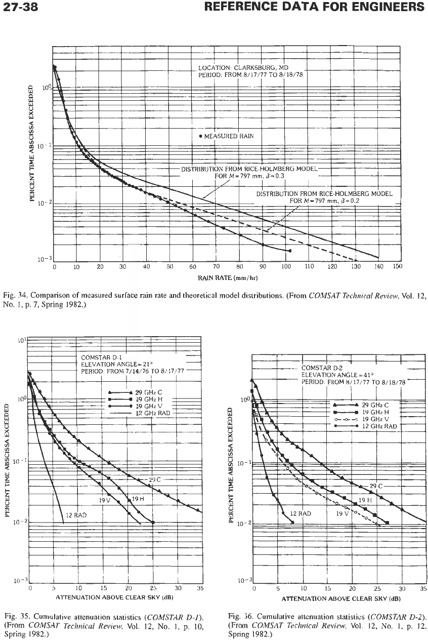
Comparative data of
measured surface rain rate and theoretical model dis-
tributions are shown in Fig. 34. Cumulative attenua-
tion statistics are shown in Figs. 35, 36, and 37.
Formulae and constants used in them
are
continuously
being refined. Although those given herein
are
ade-
quate for many purposes, see the latest ITU-R reports
for more current information.
The comparison of rain attenuation at different fre-
quencies leads to a scaling relationship of the form
with 1.7
<
CY
<
2.0.
Water-cloud attenuation is about the same as that
produced by rainfall at rates less than 5
mm/hr.
Ice-
cloud attenuation is at least two orders of magnitude
lower and hence negligible.
ELEVATION ANGLE
B
IN
DEGREES
Fig. 33. Equivalent path length versus rain rate and elevation
angle. (From
K.
Miya, Ed.,
Satellite Communications Tech-
nology.
Tokyo:
KDD
Engineering and Consulting, Inc.,
1982.)
Sky
Noise Temperature with
Rain
Neglecting the galactic contribution, the sky noise
temperature in the presence
of
rain, T,, is
T,
=
T,,IL,
+
[(L,
-
l)/L,lTm (Eq. 70)
If
the first term, which represents the contribution
of
the clear sky through the lossy rainy medium, is negli-
gible compared to the second term, one can write
T,
z
[(L,
-
l)/L,]Tm
=
T,n(l
-
(Eq. 71)
with
all
symbols
as
previously defined. Then the deci-
bel difference (excess loss) between the attenuation
caused by rain and clear sky attenuation
is
@,-A,)
I
dB
=
10
log [(T,
-
TcS)/(Trn
-
TJl (Eq. 72)
Conversely, the excess noise temperature is
(Ts
-
Tcs)
I
kelvin
=
Tm(Lr-
(Eq.
73)
Corrections should be introduced when antenna
sidelobe noise pickup and/or receiver front-end noise
27-38
I I
I I
I I
I I
h
LOCATION: CLARKSBURG, MD
PERIOD: FROM
8/17/77
TO
8/18/78
1
REFERENCE
DATA
FOR
ENGINEERS
U
I I
MEASURED RAIN
M
B
ti
kl
m
10-1
F
d
c
u
0:
10-2
10-3
0 10 20
30 40
50
60
70
80
90
100
110
120
130
140
150
RAIN RATE
(mm/hr)
Fig.
34.
Comparison
of
measured surface rain rate and theoretical model distributions. (From
COMSAT
Technical Review,
Vol.
12,
No.
1,
p.
7,
Spring
1982.)
10'
100
9
El
3
U
0
a
E
w
p
10-
1
c
6
2
e
10-2
10-3
0
5 10
15
20
25
30
35
ATTENUATION ABOVE CLEAR
SKY
(dB)
Fig.
35.
Cumulative attenuation statistics
(COMSTAR
D-1).
(From
COMSAT Technical Review,
Vol.
12,
No.
1,
p.
10,
Spring
1982.)
I
I
I
I I
1
10-
-3
0
5
10
15
20 25
30
35
ATTENUATION ABOVE CLEAR
SKY
(dB)
Fig. 36. Cumulative attenuation statistics
(COMSTAR
D-2).
(From
COMSAT Technical Review,
Vol.
12,
No.
1,
p.
12,
Spring
1982.)
SATELLITE AND SPACE COMMUNICATIONS
27-39
101-
-:
COMSTAR D-2
.
ELEVATION
ANGLE-41'
-
.
PERIOD, FROM
8/17/77
70
8/18(78
__
-
-
-
I
I
100
E)
-
19GHzV
6
i5
;s
x
$
lo-'
3
z
L
0
L"
z
t.
10-2
10-3
0
5
10
15
20
25
30
35
ATTENUATION ABOVE CLEAR
SKY
(dB)
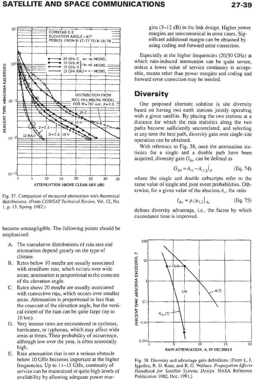
Fig.
37.
Comparison
of
measured attenuation with theoretical
distributions. (From
COMSAT Technical Review,
Vol. 12,
No.
1, p. 13, Spring 1982.)
become nonnegligible. The following points should be
emphasized
A. The cumulative distributions of rain rate and
attenuation depend greatly
on
the type of
climate.
B.
Rates below
10
mm/hr
are
usually associated
with stratiform rain, which occurs over wide
areas; attenuation is proportional
to
the cosecant
of the elevation angle.
C.
Rates above 20 mm/hr are usually associated
with convective rain, which occurs over smaller
areas. Attenuation is proportional to less than
the cosecant of the elevation angle, but the verti-
cal extent of the rain can be quite large
(up
to
10
km).
D.
Very intense rates are encountered in cyclones,
hurricanes, or typhoons, which may affect wide
areas at times. Their probability of occurrence,
although low over the year, is often seasonally
high.
E.
Rain attenuation that is not a serious obstacle
below
10
GHz
becomes important at the higher
frequencies. Up to
11-15
GHz,
continuity of
service can be maintained at quite high levels of
availability by allowing adequate power mar-
gins (3-12 dB) in the link design. Higher power
margins are uneconomical in most cases. Sig-
nificant additional margin can be obtained by
using coding and forward error correction.
Especially at the higher frequencies (20/30 GHz) at
which rain-induced attenuation can be quite severe,
unless a lower value of service continuity is accept-
able, means other than power margins and coding and
forward error correction may be needed.
Diversity
One proposed alternate solution is site diversity
based
on
having two earth stations jointly operating
with a given satellite. By placing the two stations at a
distance for which the rain statistics along the two
paths become sufficiently uncorrelated, and selecting
at any time the best path, diversity gain over single-site
operation can be obtained.
With reference to Fig. 38, once the attenuation sta-
tistics for a single and a double path have been
acquired, diversity gain
Gdiv
can be defined as
where the single and double subscripts refer to the
same value of single and joint event probabilities. 0th-
envise, for a given value of the abscissad,., the ratio
Idiv
=
PI/P1,2
I
A,
(Eq.
75)
defines diversity advantage, i.e., the factor by which
exceedance time
is
improved.
RAIN ATTENUATION.
A,
IN DECIBELS
Fig.
38.
Diversity
and
advantage
gain
definitions. (From
L.
J.
Ippolito,
R.
D. Kout,
and
R.
G.
Wallace,
Propagation Effects
Handbook for Satellite Systems Design.
NASA
Reference
Publication 1082, Dec. 1981.)
Experiments have shown that both diversity gain
and advantage increase with increasing spacing of the
two sites, but at a decreasing rate, leveling off at the
distance for which the path statistics become inde-
pendent.
Depolarization
Although very small raindrops such as those
encountered in light drizzle are spherical, the larger
drops associated with heavier rain depart substantially
from spherical shape under the combined effects of
gravity, hydrostatic forces, and aerodynamic forces.
Nonspherical drops and their canting angle cause dif-
ferential attenuation and phase shift for different wave
components and hence depolarization.
For linear- or circular-polarized waves, the power
ratio of the copolarized and cross-polarized compo-
nents
gives a measure of polarization purity or cross-polar-
ization discrimination. Once differential attenuation
A
and differential phase shift
B
are determined, cross-
polarization discrimination can be computed. For cir-
cular polarization, it is
(Eq. 77)
XPD
=
20 log,,
I
(1
+
eA'lB)/
(1
-
&-IB)
I
and for linear polarization
XPD
=
20 log,,
I(1+
tan2
x
eA+JB)/(l-
&+lB
tan
x)
I
(Eq.
78)
where
x
is the angle between the incident wave polar-
ization plane and the major axis plane of the raindrops.
With linear polarization, when
,y
=
0"
or
go",
XPD
becomes infinite; for
x
=
+45O
XPD
takes a minimum
value. With circular polarization,
XPD
is always at a
minimum. At
4
and
6
GHz, rain depolarization arises
from differential phase effects and can be a significant
impairment in dual-polarized systems.
Proper operation of frequency reuse systems with
dual polarization requires
XPD
of 27 dB or more. As a
residual coupling usually originating in the antennas
and feeds always exists, the presence of rain worsens
the situation and further reduces the value of
XPD.
Depolarization compensation networks can be used at
the earth stations to restore orthogonality.
Ice depolarization is also encountered, due to the
nonspherical shape
of
ice particles, generally encoun-
tered just above the melting layer. This can be signifi-
cant at frequencies above
15
GHz and can be identified
by the absence
of
appreciable concurrent attenuation.
EARTH STATIONS
At the earth stations that form the ground segment
of space and satellite communications systems, a vari-
ety of equipment is needed depending on: (A) function
of
the station, (B) type of service,
(C)
frequency bands
used, (D) transmitter,
(E)
receiver, and (F) antenna
characteristics.
Three categories can be distinguished:
(1)
transmit-
and-receive, (2) receive-only, and
(3)
transmit-only
stations. The first is encountered in two-way commu-
nications systems. Receive-only stations are presently
used in CATV systems in the United States and in
great numbers in DBS systems around the world.
Transmit-only earth stations are found in data collec-
tion systems and DBS feeder links. Types of service
include fixed, mobile, broadcasting, and others. Spec-
trum use is regulated by international allocations with
actual bandwidth occupancy as needed for different
services, type of traffic, and modulation.
In
satellite communications systems, earth-station
transmitter power ranges from a few watts generated
by SSPAs to about ten kilowatts generated by
klystrons or TWTs. Transmitters up
to
400
kW are
used in the deep-space network. Receivers cover a
wide range of sensitivity and bandwidth with noise
temperature from a few tens of kelvins achieved with
cryogenically cooled amplifiers to hundreds
of
kelvins
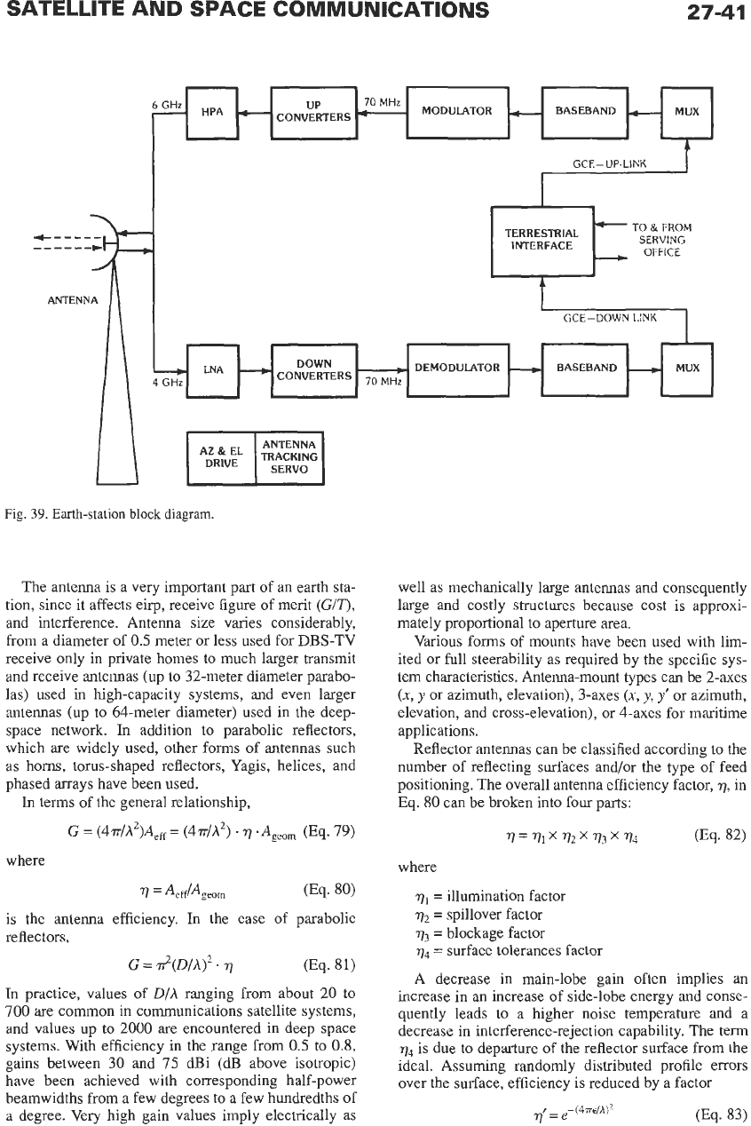
in uncooled amplifiers. A highly simplified block dia-
gram of a typical transmit-and-receive earth-station
layout is shown in Fig.
39.
The station has six major
subsystems:
A. The power subsystem
B.
The terrestrial interface
C.
The transmit chain
D.
The receive chain
E.
The antenna subsystem
F.
The control subsystem
Signal paths and functions
are
as indicated. The value
of the intermediate frequency (IF) in the receive and
transmit chains is usually the same, with 70 MHz
being commonly used. The up-link signals may be
transmitted by means of waveguides to high-power
amplifiers located just behind the feed, or in
IF
form
via coaxial cables to the up-converters and high-power
amplifiers located there. It is also possible to locate all
the equipment at the base of the antenna and to extend
the input and output feeds via beam waveguides. High-
power-amplifier
(HPA)
outputs
can be combined
through bandpass filters and circulators or by means
of
hybrids.
In
the receive chain, the weak signals from the
satellite are accepted by the same feed that carries the
transmitter output. These two signals, which differ
in
power by several orders of magnitude, are kept sepa-
rate by means of orthogonal polarizations and diplex-
ers used to enhance the separation in the frequency
domain. Orthomode transducers and polarizers are
employed, respectively, to couple orthogonally polar-
ized signals into a single waveguide and to convert lin-
ear into circular polarization and vice versa. After
preamplification in a low-noise amplifier (LNA), the
received signals are down-converted to
IF
and demod-
ulated to baseband.
SATELLITE AND SPACE COMMUNICATIONS
27-41
At,$$
TRACKING
pJ
Fig.
39.
Earth-station
block
diagram.
The antenna is a very important part of an earth sta-
tion, since it affects eirp, receive figure of merit
(GIT),
and interference. Antenna size varies considerably,
from a diameter of
0.5
meter or less used for DBS-TV
receive only in private homes to much larger transmit
and receive antennas (up to 32-meter diameter parabo-
las) used in high-capacity systems, and even larger
antennas (up to 64-meter diameter) used in the deep-
space network.
In
addition to parabolic reflectors,
which are widely used, other forms of antennas such
as horns, torus-shaped reflectors, Yagis, helices, and
phased arrays have been used.
In
terms of the general relationship,
G
=
(4‘rr/h2)AeE
=
(4../h2)
.q
.Ageom
(Eq.
79)
where
is the antenna efficiency. In the case of parabolic
reflectors,
(Eq.
8
1)
G
=
d(D/A)’.
q
In practice, values
of
D/A
ranging from about 20 to
700
are
common in communications satellite systems,
and values up to
2000
are encountered in deep space
systems. With efficiency
in
the range from
0.5
to
0.8,
gains between 30 and
75
dBi (dB above isotropic)
have been achieved with corresponding half-power
beamwidths from a few degrees to a few hundredths of
a degree. Very high gain values imply electrically as
well as mechanically large antennas and consequently
large and costly structures because cost is approxi-
mately proportional to aperture area.
Various forms of mounts have been used with lim-
ited or full steerability as required by the specific sys-
tem characteristics. Antenna-mount types can be 2-axes
(x,
y
or azimuth, elevation), 3-axes
(x,
y,
y’
or azimuth,
elevation, and cross-elevation), or 4-axes for maritime
applications.
Reflector antennas can be classified according to
the
number of reflecting surfaces and/or the type of feed
positioning. The overall antenna efficiency factor,
7,
in
Eq.
80
can be broken into four parts:
77=
vlX
72
173
q4
(Eq. 82)
where
v1
=
illumination factor
q2
=
spillover factor
v3
=
blockage factor
q4
=
surface tolerances factor
A
decrease in main-lobe gain often implies an
increase in an increase
of
side-lobe energy and conse-
quently leads to a higher noise temperature and a
decrease in interference-rejection capability. The term
q4
is due to departure
of
the reflector surface from the
ideal. Assuming randomly distributed profile errors
over the surface, efficiency is reduced by a factor
27-42
where
E
is the rms surface tolerance. As the gain loss
in
decibels is
q'IdB=685.8(~lA)2 0%.
84)
if the maximum permissible gain loss is set at
1
dB,
the rms surface tolerance,
E,
must be held to At25 or
less. The ratio
DIE
represents a measure of the quality
of a parabolic antenna. For the above-mentioned val-
ues of the
DIE
ratio, the corresponding range of the
DIE
ratio is between
500
and
25
000.
In electrically larger
antennas intended for radio astronomy, the higher
DIE
values have been achieved with protective means
against the environment. In satellite communications
systems, aside from early designs of large horn-type
antennas with radome protection against the weather,
open-air antennas are generally used." The only
weather protection device is electric heaters for melt-
ing snow and ice buildups.
The other three losses-blockage, spillover, and
illumination-apply most significantly to folded optics
systems such as the widely used Cassegrain configura-
tion, which is characterized by a hyperbolic subreflec-
tor and parabolic main reflector. Since aperture
illumination and far-field radiation are related by Fou-
rier transforms, uniform illumination leads to a sin
xlx
type of radiation pattern, unity illumination factor, but
relatively high-level side lobes. With tapering of the
illumination, the illumination factor falls below unity,
but better side-lobe control can be achieved.
Although folded optics systems such as the Casseg-
rain and Gregorian configurations provide perfect
focusing, they do not provide it with optimum aperture
illumination efficiency. Aperture efficiency can be
enhanced by appropriately shaping subreflector and
reflector to remove energy from the central area,
blocked by the subreflector and feed, and redistribut-
ing it to achieve more uniform illumination across the
remaining aperture. Such shaping can raise the gain of
a reflector antenna by more than
1
dB.
It
is most effec-
tive for antennas with
D/A
>
100.
The crowding of the geostationary orbit resulting
from the expansion of satellite systems requires very
strict control of antenna side lobes in order to satisfy
the opposite requirements of minimum mutual inter-
ference and decreased in-orbit spacing (from
5"
to
4"
to
3" and even
to
2").
The side-lobe envelope
of
most electrically large
Cassegrain antennas can be approximated by an
expression of the form
GdB,=A-Blog
I9
(Eq.
85)
*
Shipboard
antennas
of
maritime satellite communica-
tions
systems are
an
exception.
where
A
and B are constants and 0 is the off-boresight
angle.
In
1965, the CCIR (now ITU-R) adopted the
rule
The antennas of the INTELSAT system have been
standardized to follow the CCIR rule. Until 1977, side
lobes beyond
1"
from boresight were not to exceed the
-29 dB level, but after 1977 a new rule was introduced
requiring that no more than
10
percent of the side-lobe
peaks exceed the envelope as defined above. A more
recent recommendation would change the value of the
constant
A
from 32 to 29 in the above expression.
Increasingly,
to
meet the more stringent side-lobe
requirements, earth-station antennas are being built in
offset configurations. By placing the feed structure
below the reflector optical line of sight, the reflector
aperture remains unblocked, and much lower side
lobes can be realized.
The parameter that characterizes system perfor-
mance is the
GI
T
ratio, usually expressed in dB/K. All
contributions to the system noise temperature must be
properly taken into account once the measurement port
is chosen. Antenna-feed design is of great importance
with regard to both gain and side-lobe considerations
(as well as polarization).
The amounts of spillover and illumination taper for
both the subreflector and main reflector depend on the
design of the feed system. Much progress has occurred
in the transition from pyramidal to conical horns of
various types such as single mode (TE,,), multimode
(TE,,
+
TM,,), and hybrid mode
(EH,,).
In
the last
mentioned case, corrugated horns with
A/4
grooves
have made it possible to increase bandwidth, improve
symmetry of the radiation pattern, reduce the side
lobes, and achieve better off-axis polarization charac-
teristics, a feature of special importance in dual-polar-
ization systems.
In
this case, the isolation between the
two orthogonally polarized co-frequency channels
should be as high as possible. Experience in systems
using linear or circular orthogonal polarizations has
confirmed that 30-dB isolation is a representative
design goal.
Sophisticated orthomode junctions and an arrange-
ment of cascaded polarizers
are
required to satisfy the
above-mentioned requirements.
The actual isolation depends
on
the polarization
purity of the signal source and of the antenna system.
Since rain along the signal path depolarizes the signal,
automatic means of depolarization correction have
been successfully introduced at
614
GHz.
When needed, monopulse tracking systems are
employed
to
correct continuously the pointing of the
antenna in the direction of the satellite. To maintain
continuity of service, an auxiliary power source is pro-
vided as well as redundant communications equipment.
27-43
Much of the foregoing description of earth stations
applies to those used as gateways for the PSTN. In the
1980s, a marked change occurred in the application
of
satellite communications. Many classes of earth sta-
tions are unmanned, located
on
the user’s premises,
mobile and with low
Gi
T,
receive-only, electrically
small, or combinations of these qualities. As previ-
ously mentioned, VSATs are usually at the user’s pre-
mises, unmanned, and relatively small. USATs are
similarly deployed. The numbers of user’s premises
earth stations is rising rapidly, as is the amount of traf-
fic they carry. DBS-TV home stations are
on
the user’s
premises, receive-only, and electrically fairly small.
Mobile terminals for aircraft, land mobile, and smaller
ships are
on
the user’s premises (vehicle), mobile and
with low
Gi
T
(<
-10 dB/K) (and thus often suffer from
multipath), and quite small electrically. The emerging
handset terminals are even smaller physically and elec-
trically. Terminals used for IBS or its domestic equiva-
lents are usually
on
the user’s premises and often
unmanned.
What has made much of this possible is the avail-
ability of highly reliable low-cost LSICs, VLSICs, and
DSPs, along with advances
in
modulation, coding, and
protocols for baseband modules, and solid-state MICs
and more recently MMICs of moderate cost and high
reliability at microwave frequencies. Combined with
the higher eirps available
in
satellites in service in the
1980s and 1990s, services using earth terminals such
as those described above have greatly expanded and
the expansion will increase at least at the same rate in
the first decade of the 21st century.
REFERENCES
1.
Gordon, G.
D.,
in
Communications Satellite
Handbook,
W. L. Morgan, Ed. New York: John
Wiley
&
Sons, 1989.
2.
Satellite Communications Systems: Systems, Tech-
niques and Technology,
3rd ed., Wiley Series in
Communication and Distributed Systems by Ger-
ard Maral, Michel Bousquet, and Michele Bousquet.
New York: John Wiley
&
Sons, 1998.
3.
The Satellite Communication Applications Hand-
book
(Artech House Telecommunications Library)
by Bruce R. Elbert. Norwood, MA: Artech House,
1997.
4.
Space Communications,
Special Issue “Global
Satellite Communications Technology and Sys-
tems,”Vol. 16, Nos. 2 and
3,
2000.
5.
Satellite Communications
(CRL Wave Summit
Course series), T. Iida, Ed. Ohmsha, Ltd. and
10s
Press, Netherlands, 2000.
6.
Low
Earth Orbital Satellites for Personal Commu-
nication Networks
(Artech House Mobile Com-
munications Library) by Abbas Jamalipour.
Norwood, MA: Artech House, 1998.
7. Ippolito, L.
J.,
Propagation Effects Handbook for
Satellite Systems Design.
NASA Reference Publi-
cation 1082(04), Feb. 1989.
8.
Proceedings
of
the IEEE,
Special Issue
on
“Satel-
lite Communications,” Vol. 78, No. 7, July, 1990.
9. Estabrook,
P.,
and Motamedi, M. “Use of Non-
geostationary Orbits for K,-band Personal Array
Satellite System.”
13th
AIAA
COMSAT System
Conference,
Los Angeles, 1990, pp. 14-24.
10.
Bousquet, M., and Maral,
6.
“Orbital Aspects and
Useful Relations from Earth-Satellite Geometry in
the Frame of Future Mobile Systems.”
13th
AIAA
COMSAT System Conference,
Los
Angeles, 1990,
pp. 783-789.
11. Maral, G., de Ridder, J. J., and Evans, B. G. “Low-
Earth Orbit Satellite Systems for Communica-
tions.”
International Journal
of
Satellite Commu-
nications,
Vol. 9,
No.
4,
July-August 1991, pp.
209-226.
28
Discrete-Time Signal
Processing
W.
Kenneth Jenkins,
Douglas
L.
Jones,
and
Bill
J.
Hunsinger
Introduction
28-2
Fundamentals for Discrete-Time Systems
28-2
Basic Definitions
Finite Convolution and Difference Equations
The Z-Transform
The Discrete-Time Fourier Transform
Sampling and Reconstruction
Discrete Fourier Transform
28-7
Definitions and Properties
FFT Algorithms
The FFT
in
Spectral Analysis
Digital-Filter Design
28-12
IIR Filters
FIR Filters
Digital-Filter Implementation
28-1
6
Network Structures
Finite Wordlength Effects
Adaptive Digital Signal Processing
28-22
The
LMS
Algorithm for
FIR
Adaptive Filters
The
LMS
Algorithm for IIR Adaptive Filters
Generic Applications of Adaptive Methods
Discrete-Time
Analog
Technologies
28-29
Switched Capacitor Circuits
Surface-Acoustic-Wave Filters
SAW Filters for
IS-95
Compatible CDMA Digital Receivers
Minimum Requirements for SAW Performance
28-1