Middleton W.M. (ed.) Reference Data for Engineers: Radio, Electronics, Computer and Communications
Подождите немного. Документ загружается.

culations are only approximate as they are based
on
the pattern peak value, instead of integrating over the
entire pattern.
When the coma loss is unacceptably large, an array
feed can be used in the transverse focal region. One
coma correction scheme sums the array element out-
puts with weighting that
is
the conjugate
of
the focal
field. As the scan angle becomes larger the array feed
must be larger, to cover the larger coma distribution.
Since the coma
is
all
on
one side of boresight, the feed
array need only cover this area, but as the azimuth scan
angle changes, the feed array must be rotated to match.
Another method requires only phase correction and
utilizes a beam-forming network connected to the feed
array. The phases at the
BEN
output are then corrected
with line lengths (in transform space) and summed.”
When a single horn is moved off axis, the surface giv-
ing the smallest diameter circle of confusion is
not
plane and
is
called the Petzval surface. The maximum-
gain surface
also
is
not
plane and deviates slightly
from the Petzval surface. Generally the precise focal
surface used is not important. Multiple-beam antennas
typically employ a cluster of horns with each horn pro-
ducing a separate beam. These configurations are
usu-
ally offset to reduce the large blockage that would
occur with a front-fed reflector. For further informa-
tion, see Rusch et a1.t
*
Rudge, A.
W.,
and Davies, D. E.
N.
“Electronically
Controllable Primary Feed for Profile-Enor Compensation of
Large Parabolic Reflectors.”
Proc.
IEE,
Vol. 117, February
1970,
pp. 351-357.
t
Rusch,
W.
V.
T.,
et
al.
“Quasi-Optical Antenna Design
and Applications.”
Handbook
of
Antenna
Design,
Vol. 1. A.
W.
Rudge et al. (Eds.). London:
Peter
Peregrinus Ltd.,
1983.
33
Electromagnetic- Wave
Propagation
Revised by
Douglass
D.
Crombie
Very-Low Frequencies-Up to 30 Kilohertz
33-3
Low and Medium Frequencies-30 to 3000 Kilohertz
33-3
High Frequencies-3 to
30
Megahertz
Angles of Departure and Arrival
Forecasts of High-Frequency Propagation
Bandwidth Limitations
Diversity
Great-Circle Calculations
33-6
Effect
of
Nuclear Explosions on Radio Propagation
33-12
Ionospheric Scatter Propagation
33-12
Meteor-Burst Propagation
33-13
Propagation Above
30
Megahertz, Line-of-Sight Conditions
33-13
Radio Refraction
Path Plotting and Profile-Chart Construction
Fresnel Zones
Required Path Clearance
Interference Between Direct and Reflected Rays
Space-Diversity Reception
Variation of Field Strength With Distance
Fading and Diversity
Atmospheric Absorption
33-
1
33-2
REFERENCE
DATA
FOR ENGINEERS
Free-Space Transmission Equations
Effective Areas of Typical Antennas
Antenna Gain Relative to Hypothetical Isotropic Antennas
Antenna Beam Width
Transmitter Power for a Required Output Signal/Noise Ratio
Knife-Edge Diffraction Propagation
33-29
Tropospheric Scatter Propagation
33-29
Earth-Space Communication
33-33
ELECTROMAGNETIC-WAVE PROPAGATION
33-3
Radio waves may be propagated* from the transmit-
ting antenna to the receiving antenna through or along
the surface of the earth, through the atmosphere, or by
reflection or scattering from natural or artificial reflec-
tors. The conductivity and dielectric constant of the
ground vary considerably from those of the atmosphere.
At very-low frequencies, ground waves may be satisfac-
torily propagated for distances of several thousand
kilometers. At high frequencies, however, the losses are
so
great that signals can be propagated for only a few
hundred kilometers by ground wave. Propagation in the
medium- and high-frequency bands is chiefly by ground
wave and by reflection from the ionosphere, and severe
fading is caused in these frequency bands by the
interference between ground and ionospheric waves.
The refractive index of the atmosphere is an impor-
tant factor in radio propagation. At frequencies between
about
100
and
8000
megahertz, scattering of radio
waves by inhomogeneities in the electromagnetic
characteristics of the atmosphere can be used to provide
satisfactory wideband communication up to several
times the line-of-sight distance. New techniques are
being developed for generating coherent high-power
waves in the optical spectrum. Atmospheric absorption
at these frequencies is high, but the large bandwidths
and small antenna beam widths may make such fre-
quencies practical for certain applications.
VERY-LOW FREQUENCIES-
UP
TO
30
KILOHERTZ
The propagation of long radio waves is of consider-
able importance in reliable communication, long-range
navigation, and the detection
of
nuclear explosions.
Considerable progress has been made in recent years in
understanding the propagation of such waves in the
earth-ionosphere waveguide.?
At short distances from a transmitter, the received
signal is chiefly by a ground or surface wave, and at
very-low frequencies its intensity is essentially inversely
proportional to distance. At greater distances, the field
intensity falls at a higher rate because of losses in the
ground and because of the curvature of the earth. These
losses increase with frequency. At sufficiently great
distances, the received level is chiefly due to sky waves
reflected from the ionosphere. At intermediate distanc-
es, the field is a combination of sky waves and ground
waves that result in an interference pattern. The total
field at the receiver may be obtained in two distinct
ways.
The
first method, which leads to the geometric-
optics theory, directly sums the contributions at the
receiver from the primary source and each of its images.
-
*
CCIR XVth Plenary Assembly, Geneva, 1982; Vol. V,
Propagation in Non-Ionized Media,
and Vol. VI,
Propagation
in
Ionized Media.
f
Watt,
A.
D.
VLF
Radio Engineering,
Vol. 14, Interna-
tional Series
of
Monographs in Electromagnetic Waves. New
York Pergamon Press, Inc., 1967.
The second method treats the source and its images as
self-illuminating diffraction gratings, one above the
earth and one below, and leads
to
the waveguide mode
theory. The advantages of mode theory are restricted to
very-low frequencies, where relatively few modes can
be supported in the earth-ionosphere waveguide. For
example, when the height of the ionosphere is 80
kilometers and the wavelength is
20
kilometers, only
the first eight modes can be supported. When the
wavelength is
2
kilometers, however, all modes up to
the 80th can be supported.
Thus at very-low frequencies, and for distances
greater than say
3000
kilometers, it
is
simpler to use the
mode of lowest order to obtain the received field. At
distances.less than about
1000
kilometers, it is simpler
to use ray theory. The above is based on an idealized
condition, since it has been assumed that the earth is
flat, that the ionosphere is sharply bounded, and that the
effect of the magnetic field of the earth can be ignored.
Even with these simplifying assumptions, the results are
useful. A full treatment
of
the general case can be
obtained by reference to several sources.
*
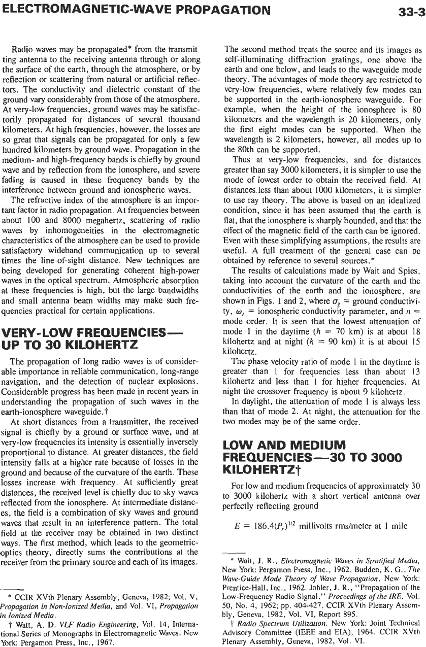
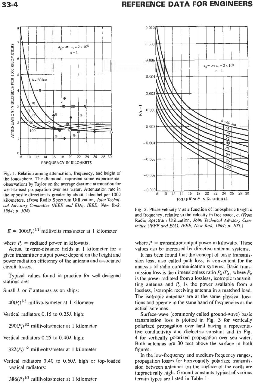
The results of calculations made by Wait and Spies,
taking into account the curvature of the earth and the
conductivities of the earth and the ionosphere, are
shown in Figs.
1
and
2,
where
ug
=
ground conductivi-
ty,
w,
=
ionospheric conductivity parameter, and
n
=
mode order. It is seen that the lowest attenuation of
mode
1
in the daytime
(h
=
70
km) is at about 18
kilohertz and at night
(h
=
90
km) it
is
at about
15
kilohertz.
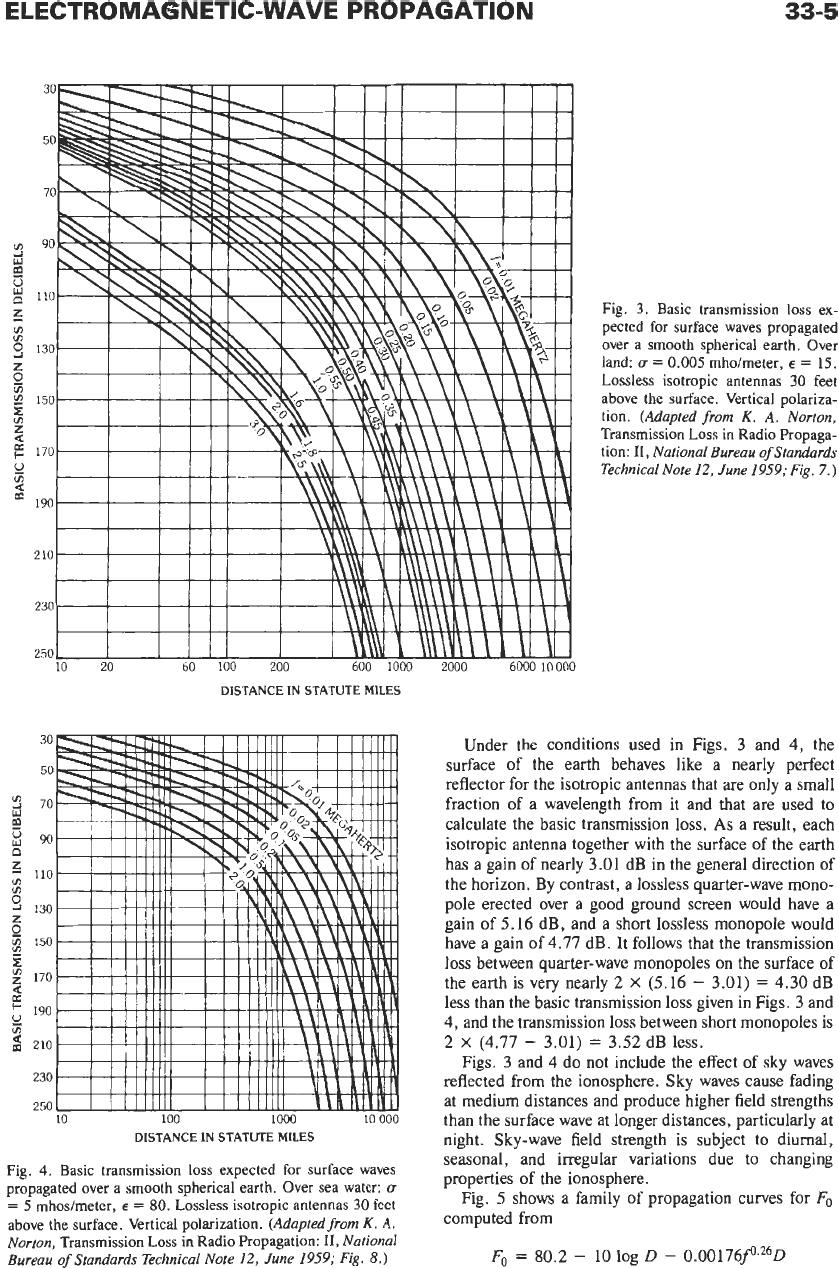
The phase velocity ratio of mode
1
in the daytime is
greater than
1
for frequencies less than about
13
kilohertz and less than
1
for higher frequencies. At
night the crossover frequency
is
about
9
kilohertz.
In daylight, the attenuation
of
mode
1
is always less
than that of mode
2.
At night, the attenuation for the
two modes may be of the same order.
LOW AND MEDIUM
KILOHERTZT
FREQUENCIES-30 TO
3000
For low and medium frequencies of approximately
30
to
3000
kilohertz with a short vertical antenna over
perfectly reflecting ground
E
=
186.4(P,)”2
millivolts rmdmeter at
1
mile
*
Wait,
J.
R.,
Electromugneric Waves in Srrutified Media,
New York: Pergamon Press, Inc., 1962. Budden,
K.
G.,
The
Wave-Guide Mode Theory
of
Wave Propagation,
New York:
Prentice-Hall, Inc., 1962. Johler,
J.
R., “Propagation
of
the
Low-Frequency Radio Signal,”
Proceedings
of
rhe IRE,
Vol.
50,
No. 4, 1962; pp. 404-427. CCIR XVth Plenary
Assem-
bly, Geneva, 1982, Vol. VI, Report 895.
f
Radio Spectrum Utilization.
New York: Joint Technical
Advisory Committee
(IEEE
and
EIA),
1964. CCIR XVth
Plenary Assembly, Geneva, 1982, Vol. VI.
33-4
REFERENCE
DATA
FOR ENGINEERS
FREQUENCY
IN
KILOHERTZ
Fig.
1.
Relation among attenuation, frequency,
and
height of
the ionosphere. The diamonds represent some experimental
observations
by
Taylor
on
the average daytime attenuation for
west-to-east propagation over sea water. Attenuation rate
in
the
opposite direction
is
greater
by
about
1
decibel per
1000
kilometers.
(From
Radio
Spectrum Utilization,
Joint Techni-
cal Advisory Committee (IEEE and EIA), IEEE,
New
York,
1964;
p.
104)
E
=
300(P,)”2 millivolts rms/meter at
1
kilometer
where
P,
=
radiated power in kilowatts.
Actual inverse-distance fields at
1
kilometer for a
given transmitter output power depend on the height and
power radiation efficiency of the antenna and associated
circuit losses.
Typical values found in practice for well-designed
stations are:
Small
L
or
T
antennas as
on
ships:
40(P,)
millivolts/meter at
1
kilometer
Vertical radiators
0.15
to
0.25h
high:
290(P,)
I”
millivolts/meter at
1
kilometer
Vertical radiators
0.25
to
0.40A
high:
322(P,)
millivolts/meter at
1
kilometer
Vertical radiators
0.40
to 0.60h high or top-loaded
vertical radiators:
386(P,)
*’*
millivolts/meter at
1
kilometer
8 10
12 14 16
18 20
22 24 26
28
30
FREQUENCY
IN
KILOHERTZ
Fig.
2.
Phase velocity Vas
a
function of ionospheric height
h
and frequency, relative to the velocity
in
free space,
c.
(From
Radio Spectrum Utilization,
Joint Technical Advisory Com-
mittee (IEEE and EIA), IEEE,
New
York, 1964;
p.
105.)
where
P,
=
transmitter output power in kilowatts. These
values can be increased by directive antenna systems.
It has been found that the concept of basic transmis-
sion loss, also called path loss, is convenient for the
analysis of radio communication systems. Basic trans-
mission loss is the dimensionless ratio
PRIPA,
where
PR
is the power radiated from a lossless, isotropic transmit-
ting antenna and
PA
is the power available from a
lossless, isotropic receiving antenna in a matched load.
The isotropic antennas are at the same physical loca-
tions and operate in the same band
of
frequencies as the
actual antennas.
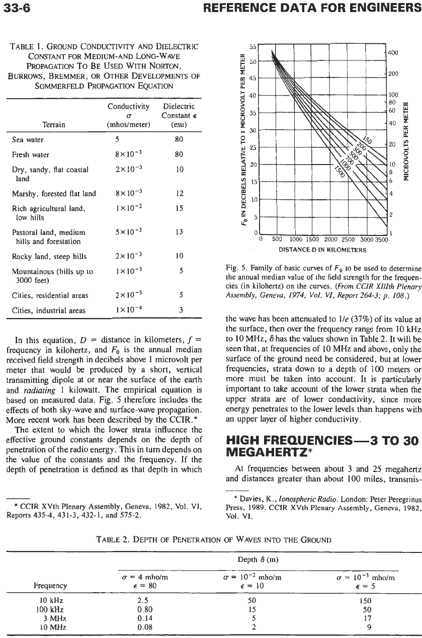
Surface-wave (commonly called ground-wave) basic
transmission loss is plotted in Fig.
3
for vertically
polarized propagation over land having a representa-
tive conductivity and dielectric constant and in Fig.
4
for vertically polarized propagation over sea water.
Both antennas are 30 feet above the surface in both
figures.
In
the low-frequency and medium-frequency ranges,
propagation losses for horizontally polarized transmis-
sion
between antennas on the surface of the earth are
impractically high. Ground constants typical of various
terrain types are listed in Table
1.
ELECTROMABNETIC-WAVE PROPAGATION
33-5
DISTANCE IN STATUTE MILES
DISTANCE IN STATUTE
MILES
Fig.
4.
Basic transmission
loss
expected for surface waves
propagated over a smooth spherical earth. Over sea water:
u
=
5
mhosheter,
E
=
80.
Lossless
isotropic antennas
30
feet
above the surface. Vertical polarization.
(Adapted from
K.
A.
Norton,
Transmission
Loss
in Radio Propagation:
11,
National
Bureau
of
Standards Technical Note
12,
June 1959;
Fig.
8.)
Fig.
3.
Basic transmission
loss
ex-
pected for surface waves propagated
over a smooth spherical earth. Over
land:
u
=
0.005
mhoheter,
E
=
15.
Lossless isotropic antennas
30
feet
above the surface. Vertical polariza-
tion.
(Adapted from
K.
A. Norton,
Transmission
Loss
in Radio Propaga-
tion:
11,
National Bureau
of
Standards
Technical Note
12,
June 1959;
Fig.
7.)
Under the conditions used in Figs. 3 and
4,
the
surface of the earth behaves like a nearly perfect
reflector for the isotropic antennas that are only a small
fraction of
a
wavelength from it and that
are
used
to
calculate the basic transmission loss.
As
a result, each
isotropic antenna together with the surface of the earth
has a gain of nearly 3.01 dB in the general direction of
the horizon. By contrast, a lossless quarter-wave mono-
pole erected over a good ground screen would have
a
gain of 5.16 dB, and a short lossless monopole
would
have a gain of 4.77 dB. It follows that the transmission
loss between quarter-wave monopoles
on
the surface of
the earth is very nearly 2
X
(5.16
-
3.01)
=
4.30 dB
less than the basic transmission loss given in Figs. 3 and
4, and the transmission loss between short monopoles is
2
X
(4.77
-
3.01)
=
3.52 dB less.
Figs.
3
and
4
do
not
include the effect of sky waves
reflected from the ionosphere. Sky waves cause fading
at medium distances and produce higher field strengths
than the surface wave at longer distances, particularly at
night. Sky-wave field strength is subject to diurnal,
seasonal, and irregular variations due to changing
properties of the ionosphere.
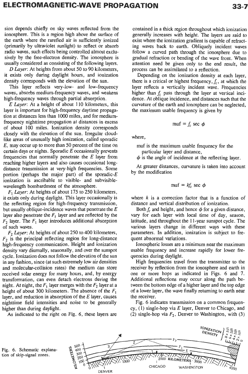
Fig.
5
shows a family of propagation curves for
Fo
computed from
Fo
=
80.2
-
10
log
D
-
0.00176f0.260
33-6
REFERENCE
DATA
FOR ENGINEERS
TABLE
1.
GROUND
CONDUCTIVITY AND
DIELECTRIC
CONSTANT FOR
MEDIUM-AND
LONG-WAVE
BURROWS,
BREMMER,
OR OTHER
DEVELOPMENTS
OF
PROPAGATION
To
BE
USED
WITH
NORTON,
SOMMERFELD
PROPAGATION
EQUATION
Conductivity
Dielectric
U
Constant
E
Terrain (mhoslmeter) (esu)
Sea water
5 80
Fresh
water
8X
80
Dry,
sandy, flat coastal 2x
10-3
10
Marshy, forested
flat
land
8X
lov3
12
land
Rich agricultural land,
1
x
10-2
15
Pastoral land, medium
5X10⁻³ 13
low
hills
hills
and forestation
Rocky land, steep hills
2x
10
Mountainous
(hills
up
to
1
X
5
Cities, residential areas
2x 5
Cities, industrial areas
ix
10-~
3
3000 feet)
In this equation,
D
=
distance in kilometers,
f
=
frequency in kilohertz, and
F,
is the annual median
received field strength in decibels above
1
microvolt per
meter that would be produced by a short, vertical
transmitting dipole at or near the surface of the earth
and
radiating
1
kilowatt. The empirical equation is
based on measured data. Fig.
5
therefore includes the
effects
of
both sky-wave and surface-wave propagation.
More recent work has been described by the
CCIR.*
The extent to which the lower strata influence the
effective ground constants depends
on
the depth of
penetration of the radio energy. This in turn depends on
the value
of
the constants and the frequency. If the
depth of penetration is defined as that depth in which
OL
I
I I
I
I
I
0
500
1000
1500
2000
2500 30003500
DISTANCE
D
IN
KILOMETERS
Fig. 5. Family
of
basic curves
of
F,
to
be
used
to
determine
the annual median
value
of the field strength
for
the frequen-
cies
(in
kilohertz)
on
the curves.
(From
CCZR
XIZZth Plenary
Assembly, Geneva,
1974,
Vol.
VI,
Report
264-3;
p.
108.)
the wave has been attenuated to
lle
(37%)
of its value at
the surface, then over the frequency range from
10
kHz
to
10
MHz,
S
has the values shown in Table
2.
It will be
seen that, at frequencies of
10
MHz and above, only the
surface of the ground need be considered, but at lower
frequencies, strata down to a depth of
100
meters
or
more must be taken into account. It is particularly
important to take account of the lower strata when the
upper strata are of lower conductivity, since more
energy penetrates to the lower levels than happens with
an upper layer of higher conductivity.
HIGH FREQUENCIES-3
TO
30
MEGAHERTZ*
At frequencies between about
3
and
25
megahertz
and distances greater than about
100
miles, transmis-
-
*
Davies,
K.,
Ionospheric Radio.
London: Peter Peregrinus
*
CCIR
XVth
Plenary
Assembly,
Geneva,
1982,
vel.
VI,
Press,
1989.
CCIR
XVth Plenary
Assembly,
Geneva,
1982,
Vol.
VI.
Reports 435-4, 431-3, 432-1, and 575-2.
TABLE
2.
DEPTH
OF PENETRATION OF WAVES INTO THE
GROUND
Depth
S
(m)
(+
=
mholm
u
=
mholm
=
4
mholm
Frequency
E
=
80
E=
10
E=5
10
kHz
2.5
50
150
100
kHz
0.80
15 50
3
MHz
0.14
5
17
10
MHz
0.08
2
9
ELECTROMAGNETIC-WAVE PROPAGATION
33-7
sion depends chiefly
on
sky waves reflected from the
ionosphere. This is a region high above the surface of
the earth where the rarefied air is sufficiently ionized
(primarily by ultraviolet sunlight) to reflect
or
absorb
radio waves, such effects being controlled almost exclu-
sively by the free-electron density. The ionosphere is
usually considered as consisting of the following layers.
D
Layer:
At heights from about 50 to
90
kilometers,
it exists only during daylight hours, and ionization
density corresponds with the elevation of the sun.
This layer reflects very-low- and low-frequency
waves, absorbs medium-frequency waves, and weakens
high-frequency waves through partial absorption.
E
Layer:
At a height of about
110
kilometers, this
layer is important for high-frequency daytime propaga-
tion at distances less than
1000
miles, and for medium-
frequency nighttime propagation at distances in excess
of about
100
miles. Ionization density corresponds
closely with the elevation of the sun. Irregular cloud-
like areas of unusually high ionization, called sporadic
E,
may occur up to more than
50
percent of the time
on
certain days or nights. Sporadic E occasionally prevents
frequencies that normally penetrate the
E
layer from
reaching higher layers and also causes occasional long-
distance transmission at very-high frequencies. Some
portion (perhaps the major part) of the sporadic-E
ionization
is
ascribable to visible- and subvisible-
wavelength bombardment of the atmosphere.
Fl
Layer:
At heights of about
175
to 250 kilometers,
it exists only during daylight. This layer occasionally is
the reflecting region for high-frequency transmission,
but usually oblique-incidence waves that penetrate the
E
layer also penetrate the layer and
are
reflected by the
F2
layer. The
F,
layer introduces additional absorption
of such waves.
F2
Layer:
At heights of about 250 to
400
kilometers,
F2
is
the principal reflecting region for long-distance
high-frequency communication. Height and ionization
density vary diurnally, seasonally, and over the sunspot
cycle. Ionization does not follow the elevation of the
sun
in any fashion, since (at such extremely low air densities
and molecular-collision rates) the medium can store
received solar energy for many hours, and, by energy
transformation, can even detach electrons during the
night, At night, the
F1
layer merges with the
F2
layer at a
height of about
300
kilometers. The absence of the
FI
layer, and reduction in absorption of the
E
layer, causes
nighttime field intensities and noise to be generally
higher than during daylight.
As
indicated
to
the right
on
Fig.
6,
these layers are
contained in a thick region throughout which ionization
generally increases with height. The layers are said
to
exist where the ionization gradient is capable of refract-
ing waves back to earth. Obliquely incident waves
follow a curved path through the ionosphere due to
gradual refraction or bending of the wave front. When
attention need be given only to the end result, the
process can be assimilated to a reflection.
Depending
on
the ionization density at each layer,
there is a critical or highest frequency,f,, at which the
layer reflects
a
vertically incident wave. Frequencies
higher than
f,
pass through the layer at vertical inci-
dence. At oblique incidence, and distances such that the
curvature of the earth and ionosphere can be neglected,
the maximum usable frequency is given by
muf
=
f,
sec
4
where,
muf is the maximum usable frequency for the
4
is the angle of incidence at the reflecting layer.
At greater distances, curvature is taken into account
particular layer and distance,
by the modification
muf
=
sec
4
where
k
is
a correction factor that is a function of
distance and vertical distribution of ionization.
Bothf, and height, and hence
4
for a given distance,
vary for each layer with local time of day, season,
latitude, and throughout the
1
1-year sunspot cycle. The
various layers change in different ways with these
parameters.
In
addition, ionization is subject to fre-
quent abnormal variations.
Ionospheric losses
are
a minimum near the maximum
usable frequency and increase rapidly for lower fre-
quencies during daylight.
High frequencies travel from the transmitter to the
receiver by reflection from the ionosphere and earth
in
one
or
more hops as indicated in Figs.
6
and 7.
Additional reflections may occur along the path be-
tween the bottom edge of a higher layer and the top edge
of a lower layer, the wave finally returning to earth near
the receiver.
Fig.
6
indicates transmission
on
a common frequen-
cy, (1) single-hop via
E
layer, Denver to Chicago, and
(2)
single-hop via
F2,
Denver
to
Washington, with
(3)
Fig.
6.
Schematic explana-
tion
of
skip-signal
zones.
DENVER
33-8
REFERENCE
DATA
FOR ENGINEERS
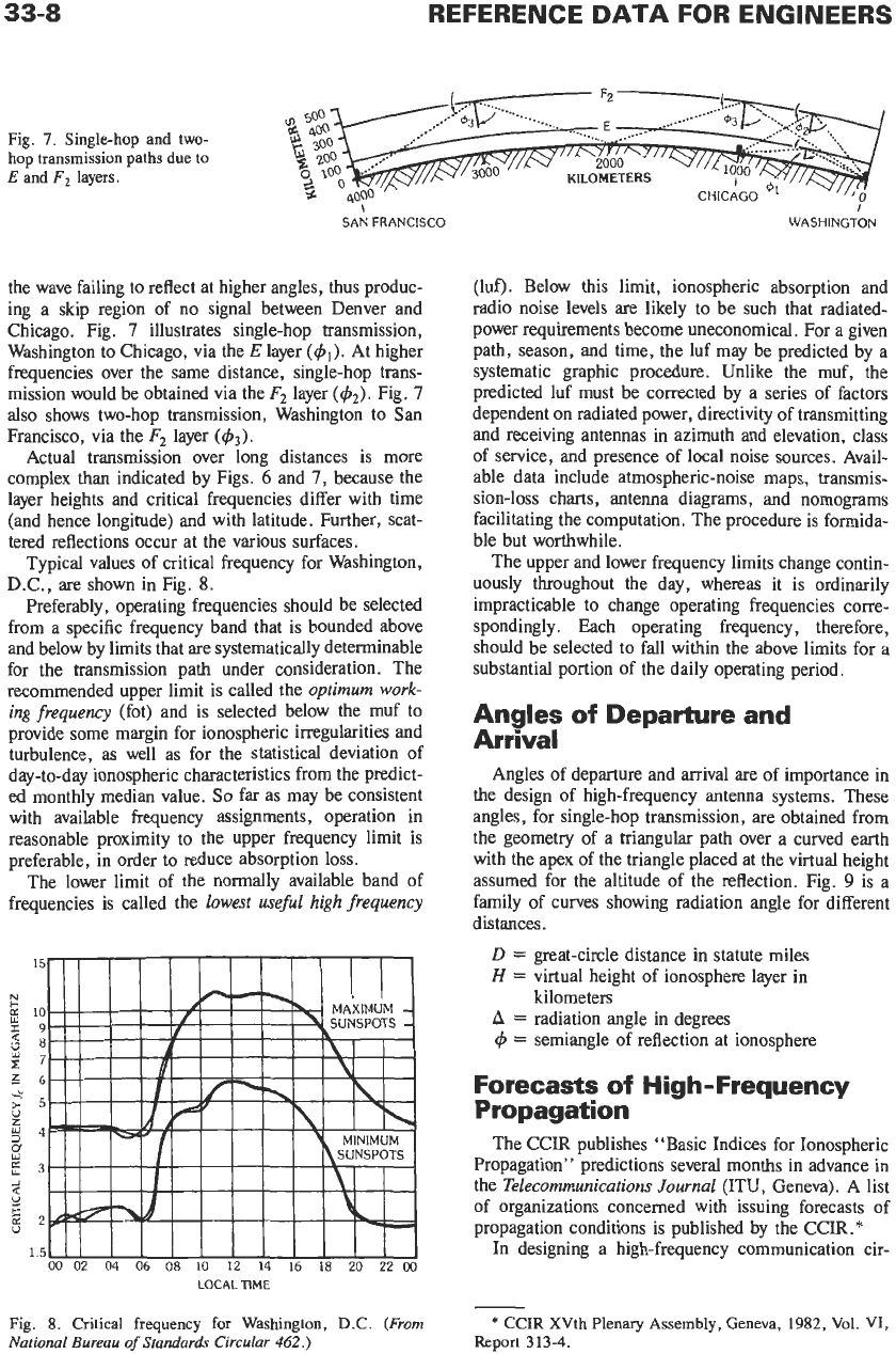
Fig. 7. Single-hop and
two-
hop transmission paths due to
E
and
F2
layers.
SAN FRANCISCO
I
WASHINGTON
the wave failing to reflect at higher angles, thus produc-
ing a skip region of
no
signal between Denver and
Chicago. Fig.
7
illustrates single-hop transmission,
Washington to Chicago, via the
E
layer
(4,).
At higher
frequencies over the same distance, single-hop trans-
mission would be obtained via the
F2
layer
(&).
Fig.
7
also shows two-hop transmission, Washington to San
Francisco, via the
F2
layer
(&).
Actual transmission over long distances is more
complex than indicated by Figs.
6
and
7,
because the
layer heights and critical frequencies differ with time
(and hence longitude) and with latitude. Further, scat-
tered reflections occur at the various surfaces.
Typical values of critical frequency for Washington,
D.C., are shown in Fig.
8.
Preferably, operating frequencies should be selected
from a specific frequency band that is bounded above
and below by limits that are systematically determinable
for the transmission path under consideration. The
recommended upper limit is called the
optimum
work-
ing frequency
(fot) and is selected below the muf to
provide some margin for ionospheric irregularities and
turbulence, as well as for the statistical deviation of
day-to-day ionospheric characteristics from the predict-
ed monthly median value.
So
far as may be consistent
with available frequency assignments, operation in
reasonable proximity to the upper frequency limit is
preferable, in order to reduce absorption loss.
The lower limit of the normally available band of
frequencies is called the
lowest
useful
high
frequency
LOCAL
TIME
(luf). Below this limit, ionospheric absorption and
radio noise levels are likely to be such that radiated-
power requirements become uneconomical. For a given
path, season, and time, the luf may be predicted by a
systematic graphic procedure. Unlike the muf, the
predicted luf must be corrected by a series of factors
dependent
on
radiated power, directivity of transmitting
and receiving antennas in azimuth and elevation, class
of service, and presence of local noise sources. Avail-
able data include atmospheric-noise maps, transmis-
sion-loss charts, antenna diagrams, and nomograms
facilitating the computation. The procedure is formida-
ble but worthwhile.
The upper and lower frequency limits change contin-
uously throughout the day, whereas it is ordinarily
impracticable to change operating frequencies corre-
spondingly. Each operating frequency, therefore,
should be selected to fall within the above limits for a
substantial portion
of
the daily operating period.
Angles
of
Departure and
Arrival
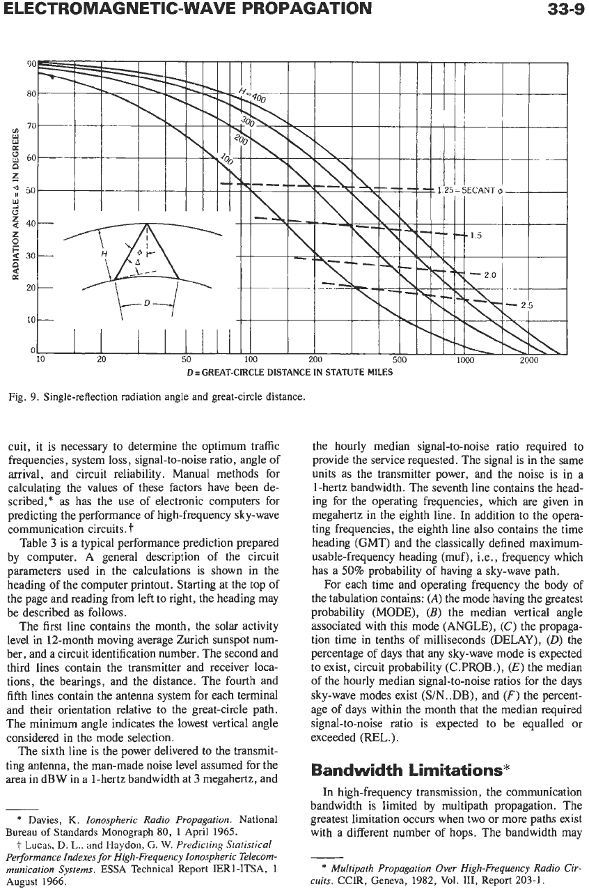
Angles of departure and arrival are of importance in
the design of high-frequency antenna systems. These
angles, for single-hop transmission,
are
obtained from
the geometry of a triangular path over a curved earth
with the apex of the triangle placed at the virtual height
assumed for the altitude of the reflection. Fig.
9
is a
family of curves showing radiation angle for different
distances.
D
=
great-circle distance in statute miles
H
=
virtual height of ionosphere layer in
A
=
radiation angle in degrees
C$
=
semiangle of reflection at ionosphere
kilometers
Forecasts
of
High-Frequency
Propagation
The CCIR publishes “Basic Indices for Ionospheric
Propagation’
’
predictions several months in advance in
the
Telecommunications Journal
(ITU, Geneva). A list
of organizations concerned with issuing forecasts of
propagation conditions is published by the CCIR.
*
In designing a high-frequency communication cir-
Fig.
8.
Critical frequency for Washington, D.C.
(From
National
Bureau
of
Standards Circular
462.)
*
CCIR XVth Plenary Assembly, Geneva,
1982, Vol.
VI,
Report
313-4.
ELECTROMAGNETIC-WAVE PROPAGATION
33-9
D
I
GREAT-CIRCLE
DISTANCE IN STATUTE
MILES
Fig.
9.
Single-reflection radiation angle
and
great-circle
distance.
cuit, it is necessary to determine the optimum traffic
frequencies, system loss, signal-to-noise ratio, angle of
arrival, and circuit reliability. Manual methods for
calculating the values of these factors have been de-
scribed,* as has the use of electronic computers for
predicting the performance of high-frequency sky-wave
communication circuits.
t
Table
3
is a typical performance prediction prepared
by computer. A general description of the circuit
parameters used in the calculations is shown in the
heading of the computer printout. Starting at the top of
the page and reading from left to right, the heading may
be described as follows.
The first line contains the month, the solar activity
level in 12-month moving average Zurich sunspot num-
ber, and a circuit identification number. The second and
third lines contain the transmitter and receiver loca-
tions, the bearings, and the distance. The fourth and
fifth lines contain the antenna system for each terminal
and their orientation relative to the great-circle path.
The minimum angle indicates the lowest vertical angle
considered in the mode selection.
The sixth line
is
the power delivered
to
the transmit-
ting antenna, the man-made noise level assumed for the
area in dBW in a 1-hertz bandwidth at
3
megahertz, and
*
Davies,
K.
Ionospheric Radio Propagation.
National
Bureau
of
Standards Monograph
80,
1
April 1965.
t
Lucas,
D.
L.,
and
Haydon,
G.
W.
Predicting Statistical
Performance Indexes for High-Frequency Ionospheric Telecom-
munication Systems.
ESSA
Technical Report IERl-ITSA, 1
August
1966.
the hourly median signal-to-noise ratio required to
provide the service requested. The signal is in the same
units as the transmitter power, and the noise is in a
1-hertz bandwidth. The seventh line contains the head-
ing for the operating frequencies, which are given in
megahertz in the eighth line. In addition to the opera-
ting frequencies, the eighth line
also
contains the time
heading (GMT) and the classically defined maximum-
usable-frequency heading
(muf),
Le., frequency which
has a
50%
probability of having a sky-wave path.
For each time and operating frequency the body of
the tabulation contains:
(A)
the mode having the greatest
probability
(MODE),
(B)
the median vertical angle
associated with this mode (ANGLE),
(C)
the propaga-
tion time in tenths of milliseconds (DELAY),
(0)
the
percentage of days that any sky-wave mode is expected
to exist, circuit probability (C.PROB.),
(E)
the median
of the hourly median signal-to-noise ratios for the days
sky-wave modes exist (S/N.
.DB),
and
(F)
the percent-
age of days within the month that the median required
signal-to-noise ratio is expected to be equalled or
exceeded (REL.).
Bandwidth Limitations*
In high-frequency transmission, the communication
bandwidth is limited by multipath propagation. The
greatest limitation occurs when two or more paths exist
with a different number of hops. The bandwidth may
*
Multipath Propagation Over High-Frequency Radio Cir-
cuits.
CCIR, Geneva, 1982,
Vol.
111, Report 203-1.