Middleton W.M. (ed.) Reference Data for Engineers: Radio, Electronics, Computer and Communications
Подождите немного. Документ загружается.

5-4
GENERAL STANDARDS
Standardization of electronic components or parts is
handled by several cooperating agencies.
In the
US,
the Electronic Industries Association
(EIA)* and the American National Standards Institute
(ANS1)t
are active in the commercial field. Electron-
tube and semiconductor-device standards are handled
by the Joint Electron Device Engineering Council
(JEDEC), a cooperative effort of EIA and the National
Electrical Manufacturers Association (NEMA)$. Mili-
tary (MIL) standards are issued by the
US
Department
of Defense or one of its agencies such as the Defense
Electronics Supply Center (DESC).
International standardization in the electronics field
is carried out by the various Technical Committees of
the International Electrotechnical Commission (1EC)O.
A
list of the available IEC Recommendations
is
includ-
ed in the ANSI Index (outside the
US,
consult the
national standardization agency or the IEC). Docu-
ments from the IEC may be used directly, or their
recommendations may be incorporated in whole or in
part in national standards issued by the EIA or ANSI. A
few broad areas may be covered by standards issued by
the International Standards Organization (ISO).
These organizations establish standards for electronic
components or parts (and in some cases, for equip-
ments) to provide interchangeability among different
products regarding size, performance, and identifica-
tion; minimum number of sizes and designs; and
uniform testing of products for acceptance. This chapter
presents a brief outline of the requirements, characteris-
tics, and designations for the major types of component
parts used in electronic equipment. Such standardiza-
tion offers economic advantages to both the parts user
and the parts manufacturer, but is not intended to
prevent the manufacture and use of other parts under
special conditions.
Color Coding
The color code
of
Table
1
is used for marking
electronic parts.
Tolerance
The maximum deviation allowed from the specified
nominal value is known as the tolerance. It is usually
given as a percentage of the nominal value, though for
very
small
capacitors the tolerance may be specified in
*
EIA Engineering Dept., Washington, D.C. Index of
standards is available. EIA was formerly Radio-Electronics-
Television Manufacturers’ Association (RETMA).
t
ANSI, New York, New York.
Index
of standards
is
available. ANSI was formerly the USA Standards Institute
(USASI).
$
NEMA, New York, New York. Index
of
standards
is
available.
8
IEC, Central Office; Geneva, Switzerland. The US
National Committee for the IEC operates within the ANSI.
picofarads (pF). For critical applications it is important
to
specify the permissible tolerance; where no tolerance
is specified, components are likely to vary by
?20
percent from the nominal value.
Do
not assume that a given lot of components will
have values distributed throughout the acceptable range
of values. A lot ordered with a
*20%
tolerance may
include
no
parts having values within
5%
of the desired
nominal value; these may have been sorted out before
shipment. The manufacturing process for a given
lot
may produce parts in a narrow range of values only, not
necessarily centered in the acceptable tolerance range.
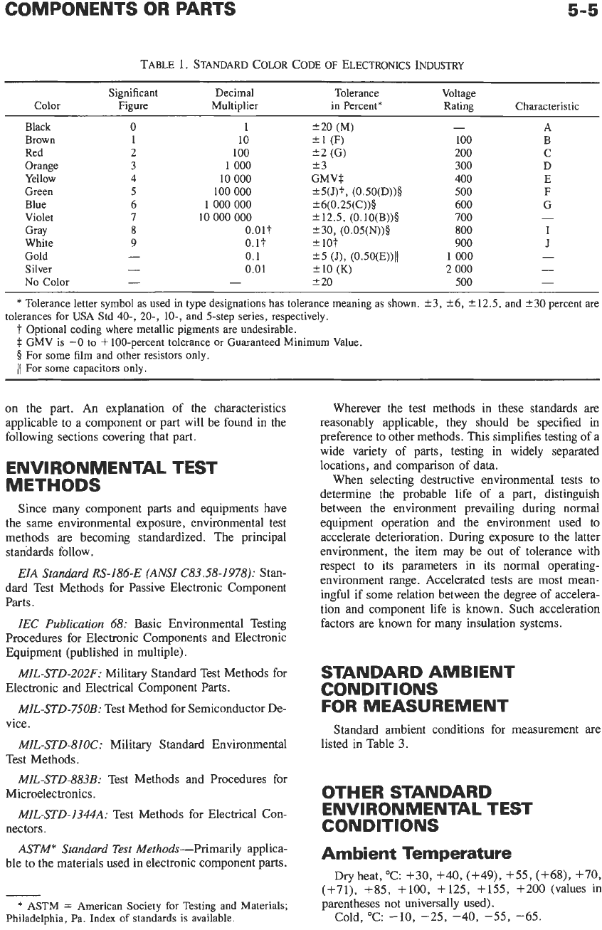
Preferred Values
To maintain an orderly progression of sizes, preferred
numbers are frequently used for the nominal values. A
further advantage is that all parts manufactured are
salable as one
or
another of the preferred values. Each
preferred value differs from its predecessor by a con-
stant multiplier, and the final result is conveniently
rounded to two significant figures.
ANSI Standard 217.1-1973 covers a series of pre-
ferred numbers based on
(lo)’”
and as listed in
Table
2.
This series has been widely used for fixed
wirewound power-type resistors and for time-delay
fuses.
Because of the established practice of using
t20-,
?lo-, and ?%percent tolerances, a series of values
based on
( (
10)”12,
and
(
has been adopted
by the EIA, and is now an ANSI Standard (C83.2-
1971) (EIA RS-385). It is widely used for such small
electronic components as fixed composition resistors
and fixed ceramic, mica, and molded paper capacitors.
These values are listed in Table
2.
(For series with
smaller steps, consult the ANSI or EIA Standard.)
Voltage Rating
Distinction must be made between the breakdown-
voltage rating (test volts) and the working-voltage rat-
ing. The maximum voltage that may be applied (usually
continuously) over a long period of time without
causing the part to fail determines the working-voltage
rating. Application
of
the test voltage for more than a
very few minutes, or even repeated applications
of
short
duration, may result in permanent damage or failure of
the part.
Characteristic
The term “characteristic” is frequently used to
include various qualities of a part such as temperature
coefficient of capacitance or resistance,
Q
value, maxi-
mum permissible operating temperature, stability when
subjected to repeated cycles of high and low tempera-
ture, and deterioration when it is subjected to moisture
either as humidity or water immersion. One or two
letters are assigned in
EIA
or MIL type designations,
and the characteristic may be indicated by color coding
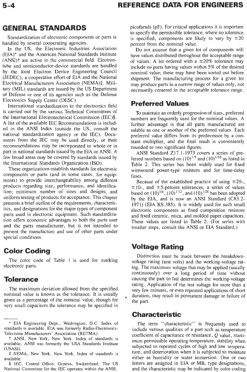
COMPONENTS OR PARTS
5-5
TABLE
1.
STANDARD COLOR CODE
OF
ELECTRONICS INDUSTRY
Significant Decimal Tolerance Voltage
Color Figure Multiplier in Percent" Rating Characteristic
A
Black
0
1
220
(M)
-
Brown
1
10
fl
(F)
100 B
Red
2
100
22
(G)
200 C
Orange
3
1
000
e3
300
D
Yellow
4
10
000
GMVt
400
E
Green
5
100
000
f
5(J)t,
(0.5O(D))§ 500
F
Blue 6
1
000 000
26(0.25(C))§ 600 G
Violet
7
10
000
000
f12.5, (O.lO(B))§
700
-
Gray
8
0.01
t
230,
(O.OS(N))§
800
I
White
9
0.
It
f10t
900
J
Gold
-
0.1
k5
(J),
(0.50(E))ll
1
000
-
Silver
-
0.01
f10
(K)
2
000
-
-
-
t20
500
-
No Color
*
Tolerance letter symbol as used in type designations has tolerance meaning as shown.
23,
26,
f
12.5,
and
f30
percent are
tolerances for USA Std
40-, 20-,
lo-, and 5-step series, respectively.
Optional coding where metallic pigments are undesirable.
$
GMV is
-0
to
+
100-percent tolerance or Guaranteed Minimum Value.
0
For
some
film and other resistors only.
11
For some capacitors only.
on
the part.
An
explanation of the characteristics
applicable to a component or part will be found in the
following sections covering that part.
ENVIRONMENTAL TEST
METHODS
Since many component parts and equipments have
the same environmental exposure, environmental test
methods are becoming standardized. The principal
standards follow.
EIA
Standard
RS-186-E (ANSI C83.58-1978):
Stan-
dard Test Methods for Passive Electronic Component
Parts.
IEC
Publication
68:
Basic Environmental Testing
Procedures for Electronic Components and Electronic
Equipment (published in multiple).
MIL-STD-202F:
Military Standard Test Methods for
Electronic and Electrical Component Parts.
MIL-STD-75OB:
Test Method for Semiconductor De-
vice.
MIL-STD-81OC:
Military Standard Environmental
MIL-STD-883B:
Test Methods and Procedures
for
MIL-STD-I344A:
Test Methods for Electrical
Con-
nectors.
ASTM*
Standard
Test
Methods-Primarily applica-
ble to the materials used
in
electronic component parts.
Test Methods.
Microelectronics.
*
ASTM
=
American Society for Testing and Materials;
Philadelphia, Pa. Index
of
standards is available.
Wherever the test methods in these standards are
reasonably applicable, they should be specified in
preference to other methods. This simplifies testing of
a
wide variety of parts, testing in widely separated
locations, and comparison of data.
When selecting destructive environmental tests to
determine the probable life of
a
part, distinguish
between the environment prevailing during normal
equipment operation and the environment used to
accelerate deterioration. During exposure to the latter
environment, the item may be out of tolerance with
respect to its parameters in its normal operating-
environment range. Accelerated tests are most mean-
ingful if some relation between the degree
of
accelera-
tion and component life is known. Such acceleration
factors are known for many insulation systems.
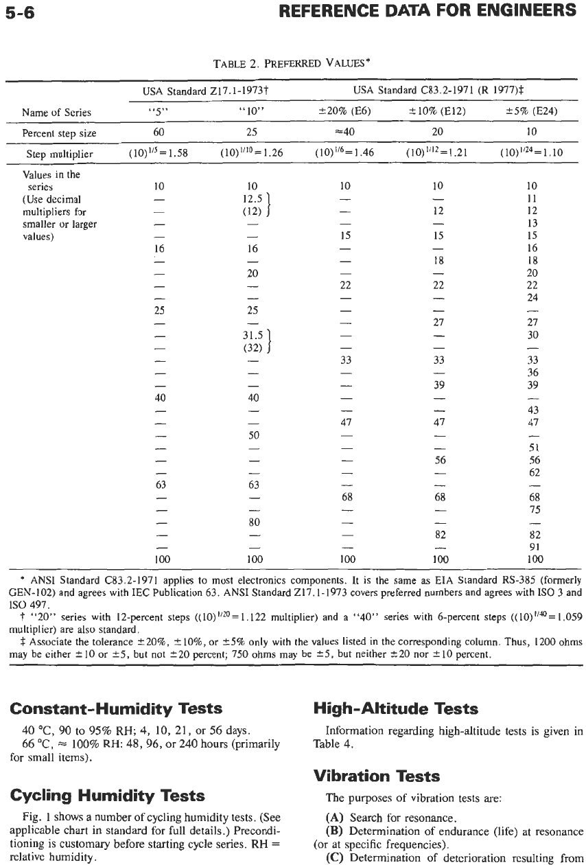
STANDARD AMBIENT
CONDITIONS
FOR MEASUREMENT
Standard ambient conditions for measurement
are
listed in Table
3.
OTHER STANDARD
ENVIRONMENTAL TEST
CONDITIONS
Ambient Temperature
Dry heat, "C:
+30,
+40,
(+49),
+55,
(+68),
+70,
(+71),
+85,
+loo,
+125, +155,
+200
(values in
parentheses not universally used).
Cold,
"C:
-10,
-25,
-40,
-55,
-65.
5-6
TABLE
2.
PREFERRED
VALUES*
USA Standard 217.1-1973t
USA Standard C83.2-1971
(R
1977)$
Name of Series
“5”
“10”
220% (E6)
f
10% (E12) 25% (E24)
Percent step size 60 25 ==40 20 10
Step multiplier (10)
=
1.58
(
10)
IiIo
=
1.26
(
10)
=
1.46 (10)”l2
=
1.21
(
=
1.10
Values in the
10 10 10 10
11
-
12 12
(Use decimal
-
13
(12)
multipliers for
-
smaller
or
larger
- -
values)
- -
15 15 15
16
16 16
- -
-
18 18
-
20
-
20
-
-
22 22 22
-
24
25 25
-
-
-
27 27
30
(32)
-
33 33 33
36
-
- -
39 39
40
40
-
43
-
-
47 47 47
51
-
-
-
56 56
-
62
63 63
-
-
68 68 68
15
-
80
-
82 82
91
100 100
100
100 100
- -
1:”5
]
series
-
-
-
-
-
-
-
-
- -
-
-
-
-
-
-
- -
-
31.5
I
-
-
-
-
-
-
-
-
-
-
- -
-
50
-
-
-
-
-
-
- -
- - -
-
-
-
-
-
-
-
- -
-
-
- -
*
ANSI
Standard (33.2-1971 applies to most electronics components. It is the same as EIA Standard RS-385 (formerly
GEN-102) and agrees with IEC Publication 63. ANSI Standard 217.1-1973 covers preferred numbers and agrees with
IS0
3 and
IS0
497.
1‘
“20” series with 12-percent steps
1.059
multiplier) are also standard.
$
Associate the tolerance +20%, +lo%, or
5%
only with the values listed in the corresponding column. Thus, 1200 ohms
may be either
*
10 or
*5,
but not 220 percent; 750 ohms may be
*5,
but neither 520 nor
2
10 percent.
1.122 multiplier) and a
“40”
series with 6-percent steps
Constant- Humidity Tests
40
“C,
90
to
95%
RH;
4,
10,
21,
or
56
days.
66
“C,
i=
100%
RH:
48,96,
or
240
hours (primarily
for small items).
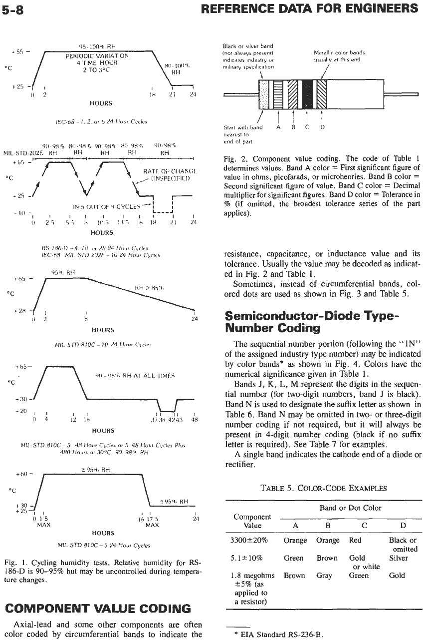
Cycling Humidity Tests
Fig.
1
shows
a
number
of
cycling humidity tests. (See
applicable chart
in
standard for full details.) Precondi-
tioning is customary before starting cycle series.
RH
=
relative humidity.
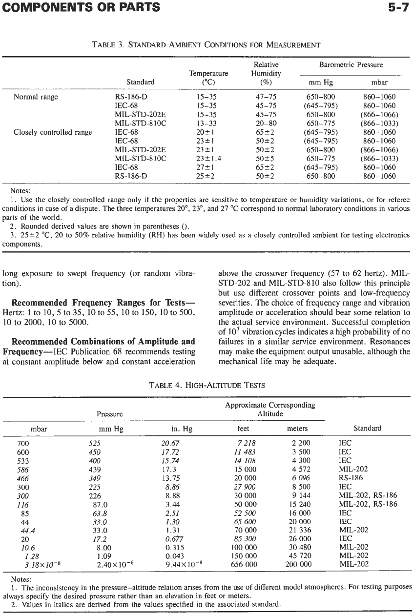
High-Altitude Tests
Information regarding high-altitude tests
is
given in
Table
4.
Vibration Tests
The purposes of vibration tests are:
(A)
Search for resonance.
(B)
Determination of endurance (life) at resonance
(C)
Determination
of
deterioration resulting from
(or
at specific frequencies).
5-7
TABLE 3. STANDARD AMBIENT CONDITIONS
FOR
MEASUREMENT
Relative Barometric Pressure
Temperature Humidity
Standard
("C)
(%)
mm Hg mbar
Normal range RS-
186-D
IEC-68
MIL-STD-202E
MIL-STD-810C
Closely controlled range
IEC-68
IEC-68
MIL-STD-202E
MIL-STD-8lOC
IEC-68
RS-186-D
15-35
15-35
15-35
13-33
202
1
2321
23C1
23k1.4
27Cl
25 52
47-75
45-75
45-75
20-80
6522
5022
50k2
5025
6522
5022
650-800
(645-795)
650-775
(645-795)
(645-795)
650-800
650-775
(645-795)
650-800
650-800
860-1060
860-1060
(866-1066)
(866-1033)
860- 1060
860-1060
(866- 1066)
(866-1033)
860-1060
860-
1060
Notes:
1.
Use the closely controlled range only if the properties are sensitive to temperature or humidity variations, or for referee
conditions in case
of
a dispute. The three temperatures
20", 23",
and
27 "C
correspond to normal laboratory conditions in various
parts
of
the world.
2.
Rounded derived values are shown in parentheses
().
3. 2522 "C, 20
to
50%
relative humidity (RH) has been widely used as a closely controlled ambient for testing electronics
components.
long exposure to swept frequency (or random vibra-
tion).
Recommended Frequency Ranges
for
Tests-
Hertz:
1
to
10,
5 to 35, 10 to 55,
10
to 150, 10 to 500,
10
to 2000, 10 to 5000.
Recommended Combinations
of
Amplitude and
Frequency-IEC
Publication
68
recommends testing
at
constant amplitude below and constant acceleration
above the crossover frequency
(57
to
62
hertz).
MIL-
STD-202 and MIL-STD-8 10 also follow this principle
but use different crossover points and low-frequency
severities. The choice of frequency range and vibration
amplitude or acceleration should bear some relation to
the actual service environment. Successful completion
of
lo7
vibration cycles indicates a high probability of no
failures in a similar service environment. Resonances
may make the equipment output unusable, although the
mechanical life may be adequate.
TABLE
4.
HIGH-ALTITUDE TESTS
Pressure
Approximate Corresponding
Altitude
mbar mm Hg in. Hg feet meters Standard
700
600
533
586
466
300
300
116
85
44
44.4
20
10.6
I
.28
3.18X10⁻⁶
525
450
400
439
349
225
226
87.0
63.8
33.0
33.0
17.2
8.00
1.09
2.40X
20.67
17.72
15.74
17.3
13.75
8.86
8.88
3.44
2.51
I
.30
1.31
0.315
0.043
0.677
9.44x
10-8
7 218
11 483
14
108
15
000
20
000
27
900
30
000
50
000
52
500
65 600
70
000
85
300
100
000
150
000
656
000
2 200
3
500
4 300
4 572
6 096
8 500
9
144
15 240
16
000
20
000
21 336
26
000
30 480
45 720
200
000
IEC
IEC
IEC
RS-186
IEC
MIL-202, RS-186
IEC
IEC
MIL-202
IEC
MIL-202
MIL-202
MIL-202
MIL-202, RS-186
MIL-202
Notes:
1.
The inconsistency in the pressure-altitude relation arises from the
use of
different model atmospheres. For testing purposes
2.
Values in italics are derived from the values specified in the associated standard.
always specify the desired pressure rather than an elevation in feet or meters.
5-8
REFERENCE DATA FOR ENGINEERS
95-
100%
RH
PERIODIC VARIATION
4TIME HOUR
2 TO
.i°C
+55
-
xo-
10(1'k>
+25
-I
,
0
2
18
21
24
HOURS
IEC
68-
I.
2.
or
b
24
Hour
Cykr
Black
or
dwr
band
/not
always
presrntl
indicates
industry
or
military
specdication
Metallic
color
bands
usually
at
this
and
/
/tit1
Start
with
band
A
B
b
nearest
to
end
of
art
YOLYX4;
XO.YA't>
Y&93%
xo
98%
90-9fi'L
MIL-STD-202E RH RH RH RH RH
..
IN
5
OlJT
OF
9
CYCLES-:
I/
Ill
Ill
I I
0
2
5
s
4
:{
IO
5
1:3
5
lh
IX
21 24
!
L---.l
IO
-
HOURS
RS
186-0
-4.
10
ur
2X
24
Ho,rr
Cvclrr
IEC
68
MII.
STD
202E
-
IO
24
Hour
CbcIes
954,
Rti
0
2
H
HOURS
MIL
SJD
RIOC-IO
24
Hour
Cbrier
W-
9X'L
RH AT ALL TIMES
OC
24
HOURS
MIL
STD
8lOC-5
48
Hour
Cycles
or
S
48
Hour
Cycler
Plus
480
Hours
ar
30°C
YO Y8Y,
RH
+25--,
I
6
is
MAX
L
Z95uh
RH
I1
I
16
17
5
24
MAX
HOURS
MIL
STD
810C-
5
14
Hour
Cycles
Fig. 1. Cycling humidity tests. Relative humidity for RS-
186-D is
90-95%
but
may
be
uncontrolled during tempera-
ture changes.
COMPONENT
VALUE
CODING
Axial-lead and some other components are often
color coded by circumferential bands to indicate
the
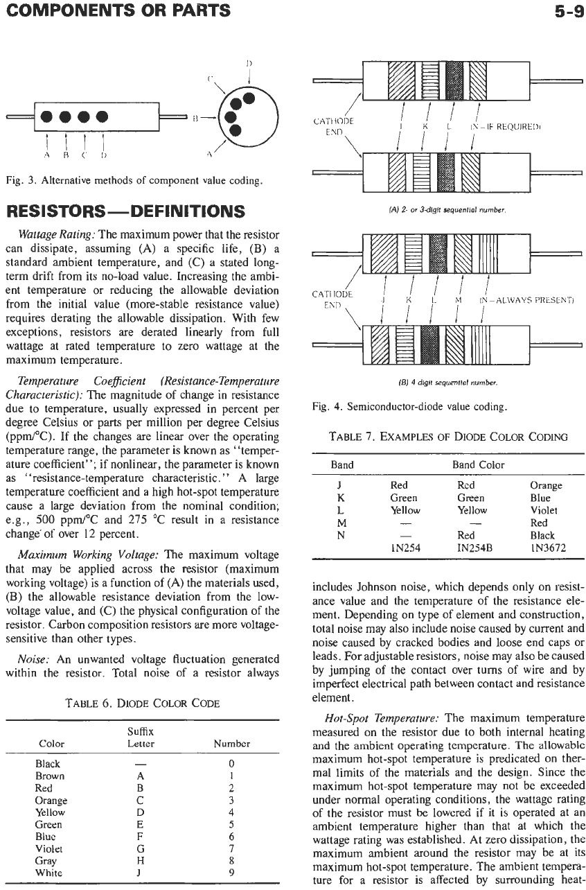
Fig.
2.
Component value coding. The code of Table 1
determines values. Band
A
color
=
First significant figure of
value in ohms, picofarads,
or
microhenries. Band B
color
=
Second significant figure of value. Band C color
=
Decimal
multiplier for significant figures. Band
D
color
=
Tolerance in
%
(if omitted, the broadest tolerance series of the part
applies).
resistance, capacitance, or inductance value and its
tolerance. Usually the value may be decoded as indicat-
ed
in Fig.
2
and Table
1.
Sometimes, instead of circumferential bands, col-
ored dots are used as shown in Fig.
3
and Table
5.
Semiconductor-Diode Type-
Number
Coding
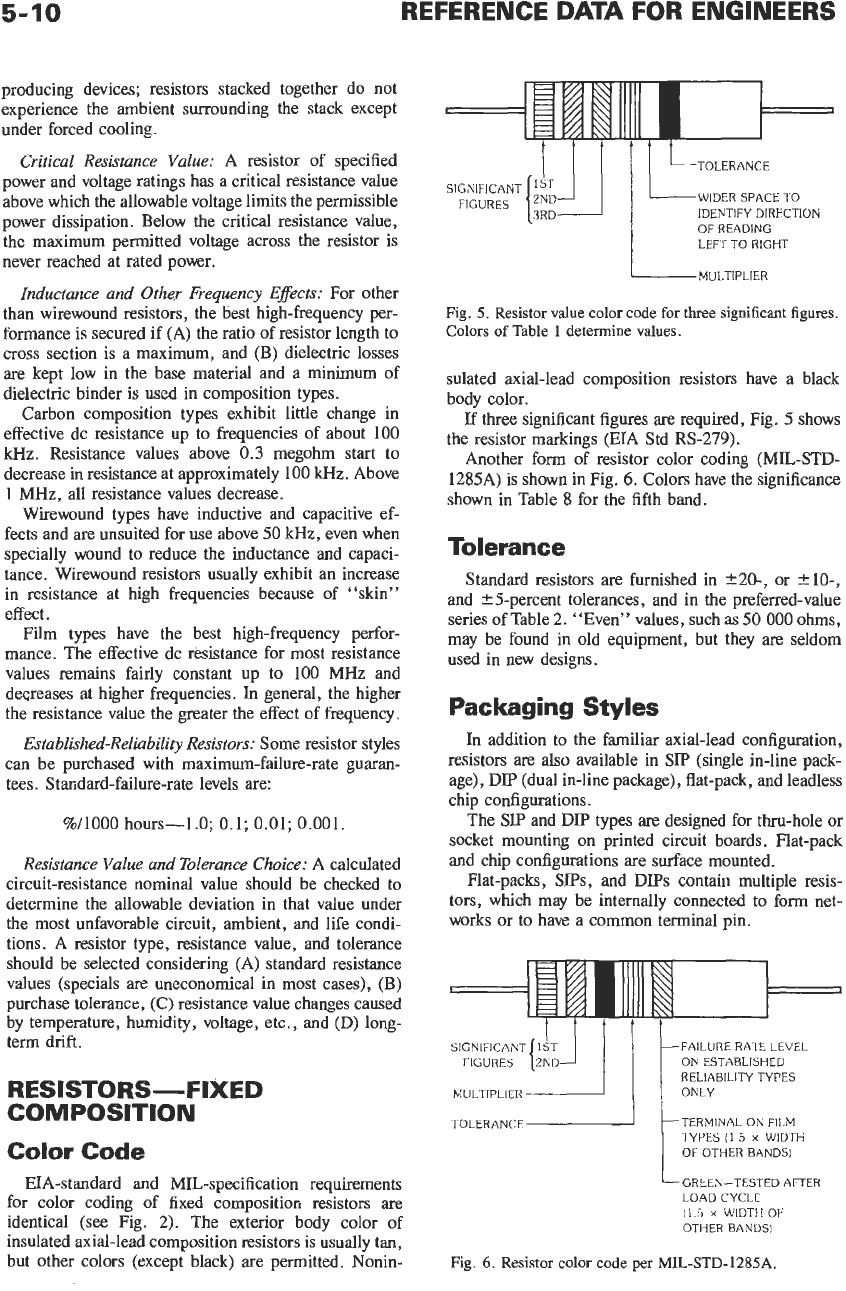
The sequential number portion (following the
"
1N"
of
the assigned industry type number) may be indicated
by color bands* as shown in Fig. 4. Colors have the
numerical significance given in Table
1.
Bands
J,
K,
L,
M
represent the digits
in
the sequen-
tial number (for two-digit numbers, band
J
is black).
Band
N
is used to designate the suffix letter as
shown
in
Table
6.
Band
N
may be omitted in two- or three-digit
number coding if not required, but it will always be
present in 4-digit number coding (black
if
no
suffix
letter is required). See Table
7
for examples.
A
single band indicates the cathode end of a diode or
rectifier.
TABLE
5. COLOR-CODE
EXAMPLES
Band or Dot Color
Component
Value
A
B
C
D
3300220%
Orange Orange Red Black or
omitted
5.1*10% Green Brown Gold Silver
1.8 megohms Brown Gray Green Gold
or white
?5%
(as
appiied
to
a resistor)
*
EIA
Standard RS-236-B.
5-9
‘i
Fig.
3.
Alternative methods
of
component
value
coding.
RESISTORS-DEFINITIONS
Wattage Rating:
The maximum power that the resistor
can dissipate, assuming
(A)
a specific life,
(B)
a
standard ambient temperature, and (C) a stated long-
term drift from its no-load value. Increasing the ambi-
ent temperature or reducing the allowable deviation
from the initial value (more-stable resistance value)
requires derating the allowable dissipation. With few
exceptions, resistors are derated linearly from full
wattage at rated temperature to zero wattage at the
maximum temperature.
Temperature Coeficient (Resistance-Temperature
Characteristic):
The magnitude of change in resistance
due to temperature, usually expressed in percent per
degree Celsius or parts per million per degree Celsius
(ppm/”C).
If
the changes are linear over the operating
temperature range, the parameter is known as “temper-
ature coefficient”; if nonlinear, the parameter is known
as “resistance-temperature characteristic.
”
A large
temperature coefficient and a high hot-spot temperature
cause a large deviation from the nominal condition;
e.g.,
500
ppm/”C and
275
“C result in a resistance
change’ of over
12
percent.
Maximum Working Voltage:
The maximum voltage
that may be applied across the resistor (maximum
working voltage) is a function of
(A)
the materials used,
(B)
the allowable resistance deviation from the low-
voltage value, and (C) the physical configuration of the
resistor. Carbon composition resistors are more voltage-
sensitive than other types.
Noise:
An unwanted voltage fluctuation generated
within the resistor. Total noise
of
a resistor always
TABLE
6.
DIODE COLOR CODE
suffix
Color
Letter
Number
Black
Brown
Red
Orange
Yellow
Green
Blue
Violet
Gray
White
-
A
B
C
D
E
F
G
H
J
0
I
2
3
4
5
6
7
8
9
(A)
2-
OT
3-dlglt
sequential number.
I/
CATHODE
I
’
M
IN-ALWAYSPRESENT]
END
(EJ
4
dlglt
sequentid number.
Fig.
4.
Semiconductor-diode value coding.
TABLE
7.
EXAMPLES
OF
DIODE COLOR CODING
Band
Band Color
J
Red Red
Orange
K
Green
Green
Blue
L
Yellow
Yellow
Violet
M
-
-
Red
N
-
Red Black
IN254 IN254B 1N3672
includes Johnson noise, which depends only on resist-
ance value and the temperature of the resistance ele-
ment. Depending on type of element and construction,
total noise may also include noise caused by current and
noise caused by cracked bodies and loose end caps or
leads. For adjustable resistors, noise may also be caused
by jumping of the contact over turns of wire and by
imperfect electrical path between contact and resistance
element.
Hot-Spot Temperature:
The maximum temperature
measured
on
the resistor due to both internal heating
and the ambient operating temperature. The allowable
maximum hot-spot temperature is predicated on ther-
mal limits of the materials and the design. Since the
maximum hot-spot temperature may not be exceeded
under normal operating conditions, the wattage rating
of the resistor must be lowered if it is operated at an
ambient temperature higher than that at which the
wattage rating was established. At zero dissipation, the
maximum ambient around the resistor may be at its
maximum hot-spot temperature. The ambient tempera-
ture for a resistor is affected by surrounding heat-
5-10
REFERENCE DATA FOR ENGINEERS
producing devices; resistors stacked together do not
experience the ambient surrounding the stack except
under forced cooling.
Critical Resistance Value:
A resistor of specified
power and voltage ratings has a critical resistance value
above which the allowable voltage limits the permissible
power dissipation. Below the critical resistance value,
the maximum permitted voltage across the resistor is
never reached at rated power.
Inductance and Other Frequency Effects:
For other
than wirewound resistors, the best high-frequency per-
formance is secured if (A) the ratio of resistor length to
cross section is a maximum, and
(€3)
dielectric losses
are kept low in the base material and a minimum of
dielectric binder is used
in
composition types.
Carbon composition types exhibit little change in
effective dc resistance up to frequencies of about 100
kHz.
Resistance values above
0.3
megohm start to
decrease
in
resistance at approximately
100
kHz.
Above
1
MHz,
all resistance values decrease.
Wirewound types have inductive and capacitive ef-
fects and are unsuited for use above
50
kHz,
even when
specially wound
to
reduce the inductance and capaci-
tance. Wirewound resistors usually exhibit an increase
in resistance at high frequencies because of
“skin”
effect.
Film types have the best high-frequency perfor-
mance. The effective dc resistance for most resistance
values remains fairly constant up to
100
MHz
and
decreases at higher frequencies.
In
general, the higher
the resistance value
the
greater the effect of frequency.
Established-Reliability Resistors:
Some resistor styles
can be purchased with maximum-failure-rate guaran-
tees. Standard-failure-rate levels are:
%/lo00
hours-1.0;
0.1;
0.01;
0.001.
Resistance Value and Tolerance Choice:
A calculated
circuit-resistance nominal value should be checked to
determine the allowable deviation in that value under
the most unfavorable circuit, ambient, and life condi-
tions. A resistor type, resistance value, and tolerance
should be selected considering
(A)
standard resistance
values (specials are uneconomical in most cases),
(B)
purchase tolerance,
(C)
resistance value changes caused
by temperature, humidity, voltage, etc., and
(D)
long-
term drift.
RESISTORS-FIXED
COMPOSITlON
Color
Code
EIA-standard and MIL-specification requirements
for color coding of fixed composition resistors are
identical (see Fig.
2).
The exterior body color
of
insulated axial-lead composition resistors is usually tan,
but other colors (except black) are permitted. Nonin-
LTOLERANCE
WIDER SPACE TO
IDENTIFY DIRECTION
OF READING
LEFT TO RIGHT
MULTIPLIER
SIGNIFICANT
FIGURES
3RD
Fig.
5.
Resistor
value
color code
for
three
significant
figures.
Colors
of
Table
1
determine
values.
sulated axial-lead composition resistors have a black
body color.
If
three significant figures are required, Fig.
5
shows
the resistor markings (EIA Std
RS-279).
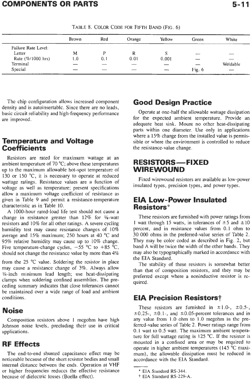
Another form of resistor color coding
(MIL-STD-
1285A) is shown in Fig.
6.
Colors have the significance
shown in Table
8
for the fifth band.
Tolerance
Standard resistors are furnished in
+20-,
or
+lo-,
and Yj-percent tolerances, and in the preferred-value
series of Table
2.
“Even” values, such as 50
000
ohms,
may be found
in
old equipment, but they are seldom
used in new designs.
Packaging Styles
In addition to the familiar axial-lead configuration,
resistors are also available in
SIP
(single in-line pack-
age),
DIP
(dual in-line package), flat-pack, and leadless
chip configurations.
The
SIP
and
DIP
types are designed for thru-hole
or
socket mounting
on
printed circuit boards. Flat-pack
and chip configurations are surface mounted.
Flat-packs,
SIPS,
and
DIPS
contain multiple resis-
tors, which may be internally connected to form net-
works
or
to have a common terminal pin.
SlGNlFlCANT 1ST FAILURE RATE LEVEL
ON
ESTABLISHED
RELIABILITY TYPES
FIGURES
{?:Dl
1
I
MULTIPLIER ONLY
TERMINAL ON FILM
TYPES
(1
5
x
WIDTH
OF
OTHER BANDS1
TOLERANCE
GREEN-TESTED AFTER
LOAD CYCLE
I1
5
x
WIDTH
OF
OTHER BANDS)
Fig.
6.
Resistor
color
code per
MIL-STD-1285A.
5-1
1
TABLE
8.
COLOR
CODE
FOR
FIFTH
BAND (FIG.
6)
Brown
Red Orange
Yellow
Green
White
Failure
Rate
Level:
-
-
Letter
M
P
R
S
Rate
(%/lo00
hrs)
1
.o
0.1
0.01
0.001
-
-
Special
-
-
-
-
Fig.
6
-
- -
Weldable
- - -
Terminal
The chip configuration allows increased component
density and is autoinsertable. Since there are no leads,
basic circuit reliability and high-frequency performance
are improved.
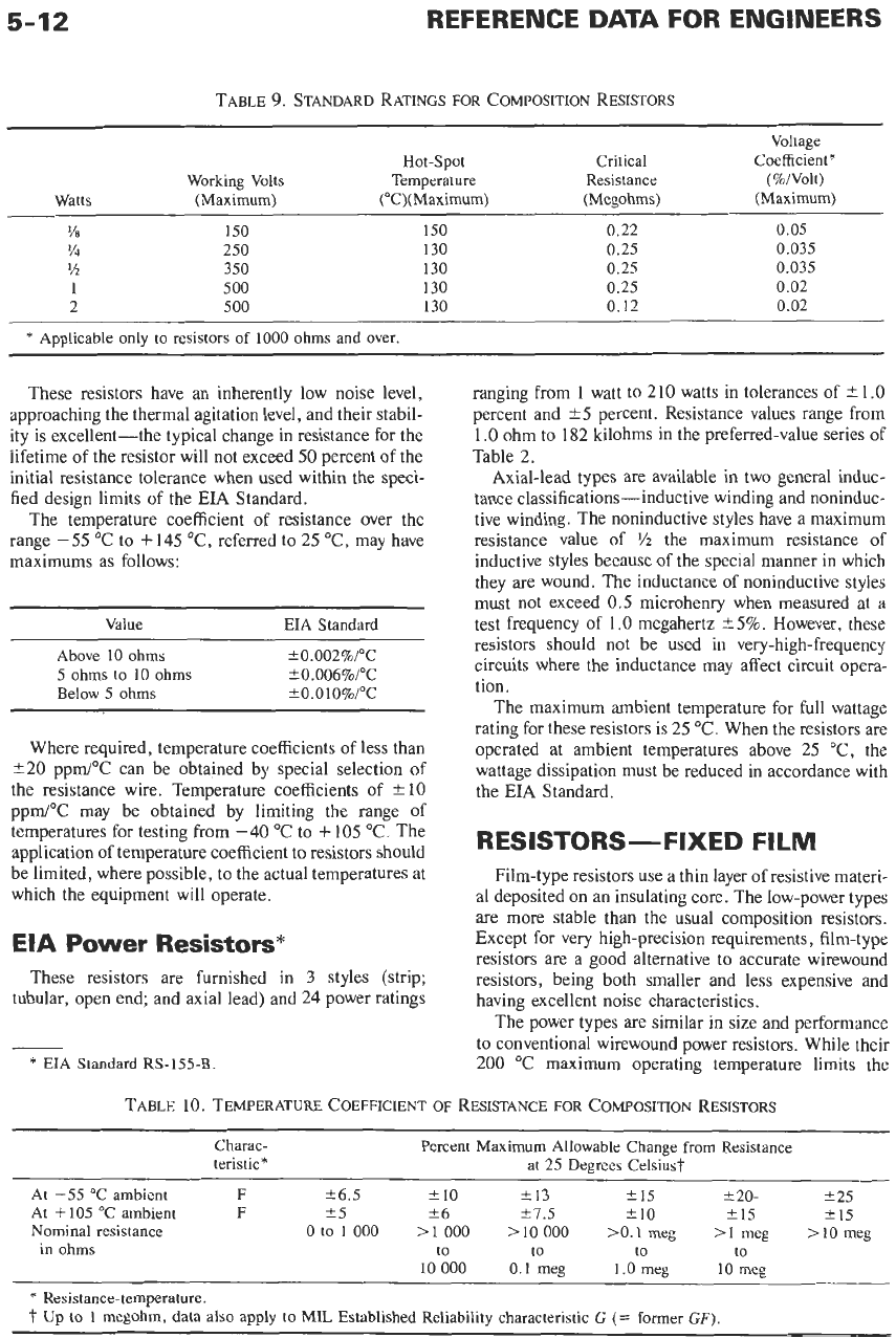
Temperature and Voltage
Coefficients
Resistors are rated for maximum wattage at an
ambient temperature of
70
"C; above these temperatures
up to the maximum allowable hot-spot temperature of
130
or
:50
"C, it is necessary to operate at reduced
wattage ratings. Resistance values are a function of
voltage as well as temperature; present specifications
allow a maximum voltage coefficient of resistance as
given in Table
9
and permit a resistance-temperature
characteristic as in Table 10.
A 1000-hour rated-load life test should not cause a
change in resistance greater than
12%
for %-watt
resistors and
10%
for all other ratings. A severe cycling
humidity test may cause resistance changes of 10%
average and
15%
maximum; 250 hours at 40 "C and
95%
relative humidity may cause up to 10% change.
Five temperature-change cycles,
-55
"C to
f85
"C,
should not change the resistance value by more than
4%
from the
25
"C value. Soldering the resistor in place
may cause a resistance change
of
3%.
Always allow
%-inch minimum lead length; use heat-dissipating
clamps when soldering confined assemblies. The pre-
ceding summary indicates that close tolerances cannot
be maintained over a wide range of load and ambient
conditions.
Noise
Composition resistors above
1
megohm have high
Johnson noise levels, precluding their use in critical
applications.
RF Effects
The end-to-end shunted capacitance effect may be
noticeable because of the short resistor bodies and small
internal distance between the ends. Operation at VHF
or higher frequencies reduces the effective resistance
because of dielectric losses (Boella effect).
Good Design Practice
Operate at one-half the allowable wattage dissipation
for the expected ambient temperature. Provide an
adequate heat sink. Mount no other heat-dissipating
parts within one diameter. Use only in applications
where a 15% change from the installed value is permis-
sible or where the environment is controlled to reduce
the resistance-value change.
RESISTORS-FIXED
WIREWOUND
Fixed wirewound resistors are available as low-power
insulated types, precision types, and power types.
EIA Low-Power Insulated
Resistors*
These resistors are furnished with power ratings from
1
watt through 15 watts, in tolerances of
25
and
-t
10
percent, and in resistance values from 0.1 ohm to
30
000
ohms in the preferred-value series of Table
2.
They may be color coded as described in Fig. 2, but
band A will be twice the width of the other bands. They
may also be typographically marked in accordance with
the EIA Standard.
The stability of these resistors is somewhat better
than that of composition resistors, and they may be
preferred except where a noninductive resistor is re-
quired.
EIA Precision Resistors?
These resistors are furnished in
?1.0-,
*OS-,
e0.25,
+O.
1-,
and 20.05-percent tolerances and in
any value from
1.0
ohm
to
1.0
megohm in the pre-
ferred-value series
of
Table 2. Power ratings range from
0.1
watt to
0.5
watt. The maximum ambient tempera-
ture for full wattage rating is 125 "C.
If
the resistor is
mounted in a confined area or may be required to
operate in higher ambient temperatures (145 "C maxi-
mum), the allowable dissipation must be reduced in
accordance with the
EIA
Standard.
*
EIA
Standard
RS-344.
t
EIA
Standard
RS-229-A.
5-12
TABLE
9.
STANDARD RATINGS
FOR
COMPOSITION RESISTORS
Voltage
Hot-Spot Critical Coefficient*
Watts (Maximum) ("C)(Maximum) (Megohms) (Maximum)
?8
150
150 0.22 0.05
?4
250
130 0.25 0.035
?2
350
130 0.25 0.035
1
500
130 0.25 0.02
2 500
130 0.12 0.02
Working Volts Temperature Resistance (%/Volt)
*
Applicable only to resistors
of
1000
ohms and over.
These resistors have an inherently low noise level,
approaching the thermal agitation level, and their stabil-
ity is excellent-the typical change in resistance for the
lifetime of the resistor will not exceed 50 percent of the
initial resistance tolerance when used within the speci-
fied design limits of the EIA Standard.
The temperature coefficient of resistance over the
range -55 'C to +145 "C, referred to 25 "C, may have
maximums as follows:
Value EIA Standard
Above
10 ohms -e0.002%/0c
5
ohms to
10
ohms
?O.O06%/"C
Below
5
ohms
*o.
0
1
O%/T
Where required, temperature coefficients of less than
e20 ppm/"C can be obtained by special selection of
the resistance wire. Temperature coefficients of
-t
10
ppm/"C may be obtained by limiting the range of
temperatures for testing from
-40
"C to
+
105 "C. The
application of temperature coefficient to resistors should
be limited, where possible, to the actual temperatures at
which the equipment will operate.
EIA
Power
Resistors*
These resistors are furnished in
3
styles (strip;
tubular, open end; and axial lead) and
24
power ratings
*
EIA
Standard RS-155-B
ranging from
1
watt to
210
watts in tolerances of
2
1
.O
percent and 25 percent. Resistance values range from
1
.O
ohm to 182 kilohms in the preferred-value series of
Table 2.
Axial-lead types are available in two general induc-
tance classifications-inductive winding and noninduc-
tive winding. The noninductive styles have a maximum
resistance value of
Yz
the maximum resistance of
inductive styles because of the special manner in which
they are wound. The inductance of noninductive styles
must not exceed 0.5 microhenry when measured at a
test frequency of
1.0
megahertz 25%. However, these
resistors should not be used in very-high-frequency
circuits where the inductance may affect circuit opera-
tion.
The maximum ambient temperature for full wattage
rating for these resistors is 25
"C.
When the resistors are
operated at ambient temperatures above 25 "C, the
wattage dissipation must be reduced in accordance with
the EIA Standard.
RES
ISTORS
-
FIXED
FI
LM
Film-type resistors use a thin layer of resistive materi-
al deposited on an insulating core. The low-power types
are more stable than the usual composition resistors.
Except for very high-precision requirements, film-type
resistors are a good alternative to accurate wirewound
resistors, being both smaller and less expensive and
having excellent noise characteristics.
The power types are similar in size and performance
to conventional wirewound power resistors. While their
200
"C maximum operating temperature limits the
TABLE
10.
TEMPERATURE COEFFICIENT
OF
RESISTANCE
FOR
COMPOSITION RESISTORS
~ ~~~
~_______
Charac-
teristic* at
25
Degrees Celsius?
Percent Maximum Allowable Change from Resistance
At
-55
"C
ambient
F
k6.5
f
10
f
13
i
15
*20-
i
25
At
+
105
'C
ambient
F
25
?6
a1.5
*
10 i15
i
15
Nominal resistance
0
to
1
000
>1
000
>10
000
>0.1
meg
>I
meg
>IO
meg
in ohms to to to
to
10
000
0.1
meg 1.0 meg
10
meg
*
Resistance-temperature.
t
Up to 1 megohm, data also apply to MIL Established Reliability characteristic
G
(=
former
GF)
5-13
power rating, the maximum resistance value available
for a given physical size is much higher than that of the
corresponding wirewound resistor.
Construction
For low resistance values, a continuous film is
applied to the core, a range of values being obtained by
varying the film thickness. Higher resistances are
achieved by the use of a spiral pattern, a coarse spiral
for intermediate values and a fine spiral for high
resistance. Thus, the inductance is greater in high
values, but it is likely to be far less than in wirewound
resistors. Special highTfrequency units having greatly
reduced inductance are available.
Resistive
Films
Resistive-material films presently used
are
micro-
crystalline carbon, boron-carbon, and various metallic
oxides
or
precious metals.
Deposited-carbon resistors have a negative tempera-
ture coefficient of 0.01 to
0.05
percent/”C for low
resistance values and somewhat larger for higher values.
Cumulative permanent resistance changes of 1 to
5
percent may result from soldering, overload, low-
temperature exposure, and aging. Additional changes
up to
5
percent are possible from moisture penetration
and temperature cycling.
The introduction of a small percentage of boron into
the deposited-carbon film results in a more stable unit.
A negative temperature coefficient of
0.005
to
0.02
percent/”C is typical. Similarly, a metallic dispersion in
thc carbon film provides a negative coefficient of 0.015
to
0.03
percent/”C. In other respects, these materials
are similar to standard deposited carbon. Carbon and
boron-carbon resistive elements have the highest ran-
dom noise of the film-type resistors.
Metallic-oxide and precious-metal-alloy films permit
higher operating temperatures. Their noise characteris-
tics are excellent. Temperature coeficients are predomi-
nantly positive, varying from
0.03
to as little as
0.0025
percenti’c.
Applications
Power ratings of film resistors are based on continu-
ous direct-current operation or on root-mean-square
operation. Power derating is necessary for operation at
ambient temperatures above the rated temperature.
In
pulse applications, the power dissipated during each
pulse and the pulse duration are more significant than
average power conditions. Short high-power pulses may
cause instantaneous local heating sufficient to alter or
destroy the film. Excessive peak voltages may result in
flashover between turns
of
the film element. Derating
under these conditions must be determined experimen-
tally.
Film resistors are fairly stable up to about
10
megahertz. Because of the extremely thin resistive film,
skin effect is small. At frequencies above 10 megahertz,
it is advisable to use only unspiraled units if inductive
effects are
to
be minimized (these are available in low
resistance values only).
Under extreme exposure, deposited-carbon resistors
deteriorate rapidly unless the element is protected.
Encapsulated or hermetically sealed units are preferred
for such applications. Open-circuiting in storage as the
result of corrosion under the end caps has been reported
in all types of film resistors. Silver-plated caps and core
ends effectively overcome this problem.
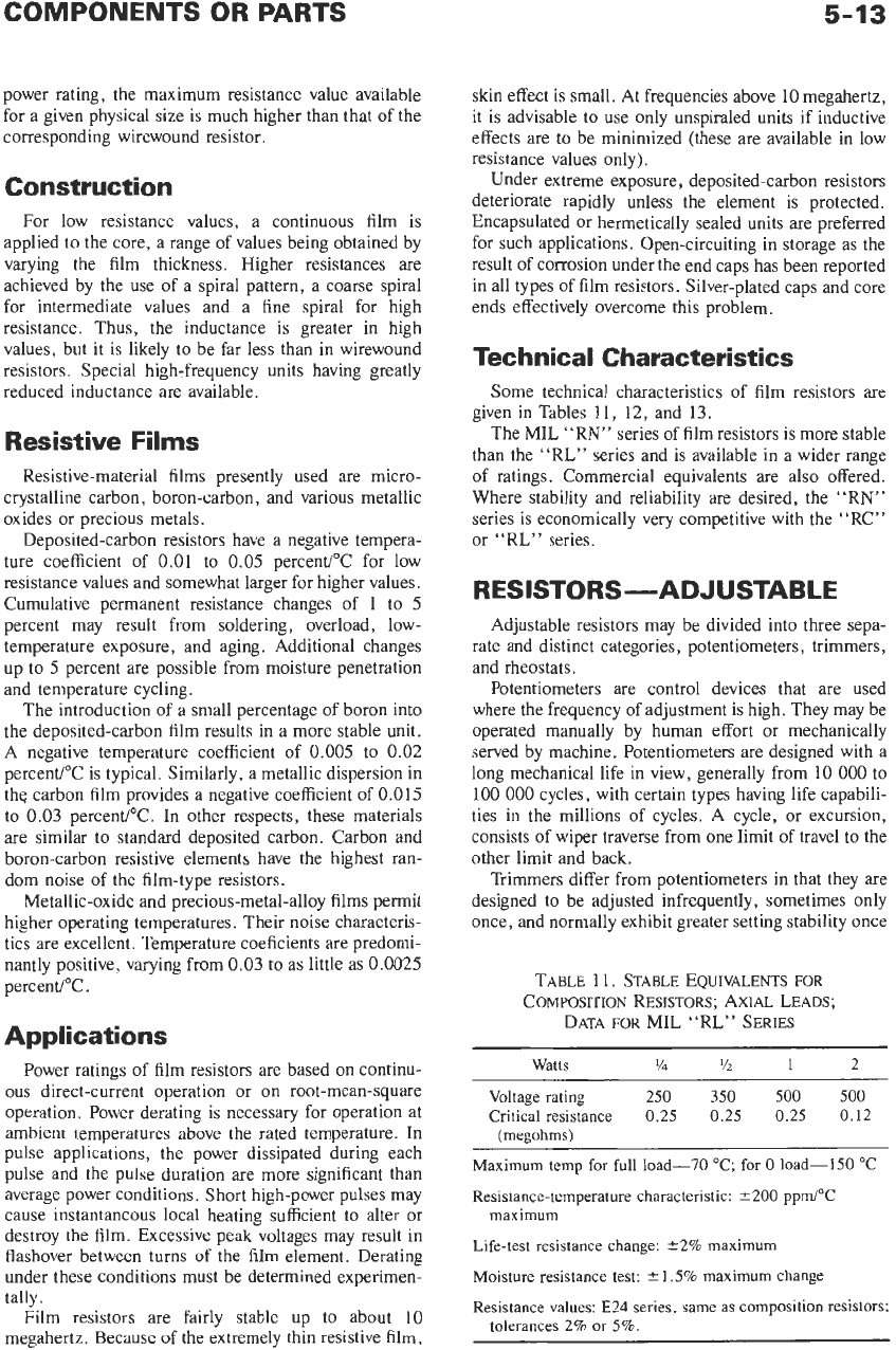
Technical Characteristics
Some technical characteristics of film resistors are
given in Tables 11,
12,
and
13.
The MIL “RN” series of film resistors is more stable
than the “RL” series and
is
available in a wider range
of ratings. Commercial equivalents are also offered.
Where stability and reliability are desired, the “RN”
series is economically very competitive with the “RC”
or “RL” series.
RESISTORS-ADJUSTABLE
Adjustable resistors may be divided into three sepa-
rate and distinct categories, potentiometers, trimmers,
and rheostats.
Potentiometers are control devices that are used
where the frequency of adjustment is high. They may be
operated manually by human effort or mechanically
served by machine. Potentiometers are designed with a
long mechanical life in view, generally from
10
000
to
100
000
cycles, with certain types having life capabili-
ties in the millions
of
cycles. A cycle, or excursion,
consists of wiper traverse from one limit of travel to the
other limit and back.
Trimmers differ from potentiometers in that they are
designed
to
be adjusted infrequently, sometimes only
once, and normally exhibit greater setting stability once
TABLE
1 1.
STABLE EQUIVALENTS
FOR
COMPOSITION RESISTORS; AXIAL LEADS;
DATA
FOR
MIL “RL” SERIES
Watts
%
YZ
1
2
Voltage rating
250
350
500 500
Critical resistance
0.25 0.25
0.25 0.12
(megohms)
Maximum
temp
for
full
load-70
“C;
for
0
load-150
“C
Resistance-temperature characteristic:
200
ppm/”C
maximum
Life-test
resistance
change:
22%
maximum
Moisture
resistance
test:
Resistance
values:
E24
series,
same
as
composition resistors;
1.5%
maximum
change
tolerances
2%
or
5%.