Middleton W.M. (ed.) Reference Data for Engineers: Radio, Electronics, Computer and Communications
Подождите немного. Документ загружается.

6-2
REFERENCE
DATA
FOR ENGINEERS
Transients-Operational Calculus and Laplace Transforms
6-19
Example
Circuit Response Related
to
Unit Impulse
Circuit Response Related to Unit Step
Heaviside Expansion Theorem
Application to Linear Networks
FUNDAMENTALS
OF
NETWORKS
6-3
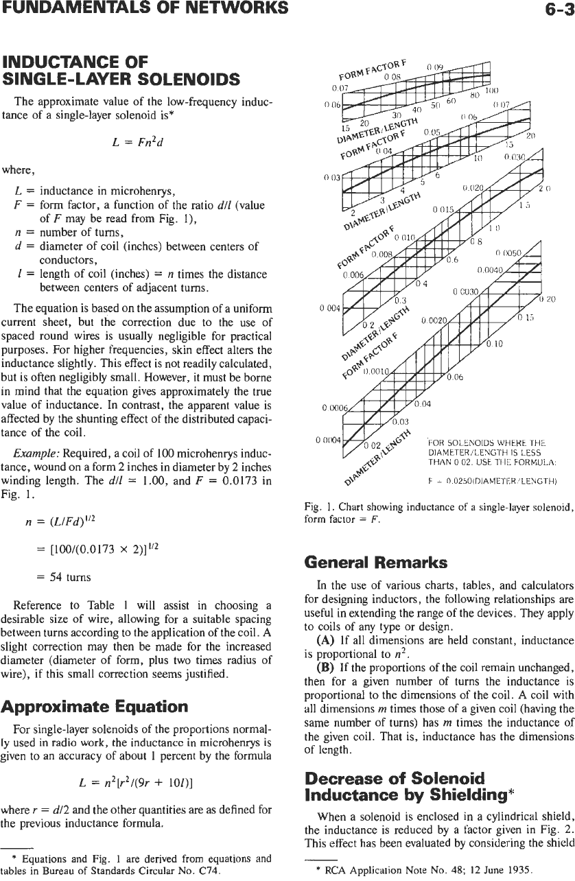
INDUCTANCE OF
SINGLE-LAYER SOLENOIDS
tance of a single-layer solenoid is*
The approximate value of the low-frequency induc-
L
=
Fn2d
where,
L
=
inductance in microhenrys,
F
=
form factor, a function of the ratio
d/l
(value
n
=
number of turns,
d
=
diameter of coil (inches) between centers of
conductors,
1
=
length of coil (inches)
=
n
times the distance
between centers of adjacent turns.
The equation is based on the assumption of a uniform
current sheet, but the correction due to the use of
spaced round wires is usually negligible for practical
purposes. For higher frequencies, skin effect alters the
inductance slightly. This effect is not readily calculated,
but is often negligibly small. However, it must be borne
in mind that the equation gives approximately the true
value of inductance. In contrast, the apparent value is
affected by the shunting effect of the distributed capaci-
tance of
the
coil.
Example:
Required, a coil of
100
microhenrys induc-
tance, wound on a form
2
inches in diameter by
2
inches
winding length. The
dll
=
1.00, and
F
=
0.0173 in
Fig. 1.
of
F
may be read from Fig. l),
n
=
(L/Fd)”*
=
[100/(0.0173
X
2)]”2
=
54
turns
Reference to Table 1 will assist in choosing a
desirable size of wire, allowing for a suitable spacing
between turns according to the application of the coil.
A
slight correction may then be made for the increased
diameter (diameter of form, plus two times radius of
wire), if this small correction seems justified.
Approximate Equation
For single-layer solenoids of the proportions normal-
ly
used
in
radio work, the inductance in microhenrys is
given to an accuracy of about 1 percent by the formula
L
=
n2[r2/(gr
+
10Z)l
where
r
=
d/2
and the other quantities are
as
defined for
the previous inductance formula.
-
*
Equations
and
Fig.
1
are derived from equations and
tables
in
Bureau
of
Standards
Circular
No.
C74.
n
20
FOR
SOLENOIDS
WHERE
THE
DIAMETER/LENGTH
IS
LESS
THAN
0
02
USE
THE FORMULA
F
=
0
0250(DIAMETER’LENGTH)
Fig. 1. Chart showing inductance
of
a
single-layer solenoid,
form
factor
=
F
General Remarks
In the use of various charts, tables, and calculators
for designing inductors, the following relationships are
useful in extending the range of the devices. They apply
to coils of any type or design.
(A)
If all dimensions are held constant, inductance
is proportional to
n2.
(B)
If the proportions of the coil remain unchanged,
then for a given number of turns the inductance is
proportional to the dimensions of the coil.
A
coil with
all dimensions
m
times those
of
a given coil (having the
same number of turns) has
m
times the inductance of
the given coil. That is, inductance has the dimensions
of length.
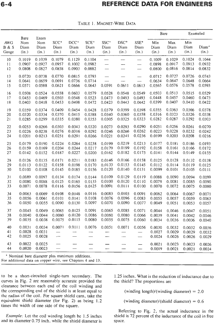
Decrease
of
Solenoid
Inductance
by
Shielding*
When a solenoid
is
enclosed in a cylindrical shield,
the inductance is reduced by a factor given in Fig.
2.
This effect has been evaluated by considering the shield
*
RCA
Application Note
No.
48;
12
June
1935.
6-4
TABLE
1.
MAGNET-WIRE DATA
Bare
Enameled
Bare Enam
AWG
Nom
Nom
SCC*
DCC*
SCE*
SSC*
DSC*
SSE*
Min
Max
Min
B
&
S
Diam Diam
Diam
Diam Diam
Diam
Diam Diam
Diam Diam Diam Diam*
Gauge
(in.) (in.)
(in.)
(in.)
(in.) (in.)
(in.)
(in.)
(in.)
(in.) (in.) (in.)
10
11
12
13
14
15
16
17
18
19
20
21
22
23
24
25
26
27
28
29
30
31
32
33
34
35
36
37
38
39
40
41
42
43
44
0.1019
0.0907
0.0808
0.0720
0.0641
0.0571
0.0508
0.0453
0.0403
0.0359
0.0320
0.0285
0.0253
0.0226
0.0201
0.0179
0.0159
0.0142
0.0126
0.0113
0.0100
0.0089
0.0080
0.0071
0.0063
0.0056
0.0050
0.0045
0.0040
0.0035
0.0031
0.0028
0.0025
0.1039
0.0927
0.0827
0.0738
0.0659
0.0588
0.0524
0.0469
0.0418
0.0374
0.0334
0.0299
0.0266
0.0238
0.0213
0.0190
0.0169
0.0152
0.0135
0.0122
0.0108
0.0097
0.0088
0.0078
0.0069
0.0061
0.0055
0.0049
0.0044
0.0038
0.0034
0.003
1
0.0028
0.1079
0.1129 0.1104
-
0.0957 0.1002 0.0982
-
0.0858
0.0903 0.0882
-
0.0770
0.0815
0.0793
-
0.0691 0.0736
0.0714
-
0.0621 0.0666 0.0643 0.0591
0.0558 0.0603 0.0579 0.0528
0.0503
0.0548 0.0523
0.0473
0.0453
0.0498 0.0472
0.0423
0.0409
0.0454 0.0428
0.0379
0.0370
0.0415
0.0388 0.0340
0.0335
0.0380 0.0353
0.0305
0.0303
0.0343 0.0320
0.0273
0.0276
0.0316 0.0292
0.0246
0.0251
0.0291
0.0266 0.0221
0.0224
0.0264
0.0238 0.0199
0.0204
0.0244 0.0217
0.0179
0.0187 0.0227 0.0200 0.0162
0.0171 0.0211 0.0183 0.0146
0.0158
0.0198 0.0170
0.0133
0.0145 0.0185
0.0156 0.0120
0.0134
0.0174 0.0144
0.0109
0.0125 0.0165
0.0135 0,0100
0.0116
0.0156
0.0125 0.0091
0.0108
0.0148 0.01 16
0.0083
0.0101 0.0141
0.0108
0.0076
0.0090
0.0130
0.0097 O.GO70
0.0085
0.0125
0.0091 0.0065
0.0080
0.0120 0.0086
0.0060
0.0075
0.01 15
0.0080 0.0055
0.0071
0.01
11
0.0076 0.0051
- -
-
-
-
-
-
-
-
-
-
-
-
0.061
1
0.0548
0.0493
0.0443
0.0399
0.0360
0.0325
0.0293
0.0266
0.0241
0.0219
0.0199
0.0182
0.0166
0.0153
0.0140
0.0129
0.0120
0.011
1
0.0103
0.0096
0.0090
0.0085
0.0080
0.0075
0.0071
-
-
-
0.1009 0.1029 0.1024 0.1044
-
0.0898 0.0917 0.0913 0.0932
-
0.0800 0.0816 0.0814
0.0832
-
0.0712
0.0727 0.0726
0.0743
-
0.0634
0.0647
0.0648 0.0664
0.0613 0.0565
0.0576
0.0578 0.0593
0.0549 0.0503
0.0513
0.0515 0.0529
0.0493 0.0448
0.0457 0.0460 0.0473
0.0442 0.0399
0.0407 0.0410 0.0422
0.0398 0.0355
0.0363 0.0366 0.0378
0.0358 0.0316
0.0323
0.0326 0.0338
0.0323 0.0282
0.0287 0.0292 0.0303
0.0290 0.0251
0.0256 0.0261 0.0270
0.0262 0.0223
0.0228 0.0232 0.0242
0.0236 0.0199
0.0203
0.0208 0.0216
0.0213
0.0177 0.0181 0.0186 0.0193
0.0192 0.0158
0.0161
0.0166 0.0172
0.0175
0.0141 0.0144
0.0149 0.0155
0.0158
0.0125 0.0128 0.0132 0.0138
0.0145
0.01 12 0.01 14
0.01
19 0.0125
0.0131 0.0099
0.0101
0.0105 0.0111
0.01 19
0.0088 0.0090
0.0094 0.0099
0.0110
0.0079 0.0081
0.0085 0.0090
0.0100 0.0070
0.0072
0.0075 0,0080
0.0091
0.0062 0.0064
0.0067 0.0071
0.0083
0.0055 0.0057
0.0059 0.0063
0.0077
0.0049
0.0051
0.0053 0.0057
0.0071
0.0044
0.0046
0.0047 0.0051
0.0066
0.0039
0.0041
0.0042 0.0046
0.0060
0.0034
0.0036 0.0036
0.0040
0.0056
0.0030
0.0032
0.0032 0.0036
-
0.0027
0.0029
0.0029 0.0032
-
0.0024
0.0026
0.0026 0.0029
0.0022
0.0025
-
-
-
- -
-
0.0021
0.0023 0.0023
0.0026
0.0020
0.0023
-
-
-
- -
-
0.0019
0.0021
0.0021 0.0024
*
Nominal bare diameter
plus
maximum additions.
For
additional
data
on
copper wire,
see
Chapters
4
and
13.
to be a short-circuited single-turn secondary. The
curves in Fig. 2 are reasonably accurate provided the
clearance between each end of the coil winding and
the corresponding end
of
the shield is at least equal to
the radius
of
the coil. For square shield cans, take the
equivalent shield diameter (for Fig.
2)
as being
1.2
times the width of one side of the square.
1.25
inches. What is the reduction of inductance due to
the shield? The proportions are
(winding length)/(winding diameter)
=
2.0
(winding diameter)/(shield diameter)
=
0.6
Referring to Fig.
2,
the actual inductance in the
shield is 72 percent of the inductance of the coil in free
space.
Example:
Let the coil winding length be
1.5
inches
and its diameter 0.75 inch, while the shield diameter
is
FUNDAMENTALS
OF
NETWORKS
6-5
WINDING LENGTH/WINDING DIAMETER
Fig.
2.
Inductance decrease when
a
solenoid
is
shielded.
By permission
of
RCA,
copyright proprietor.
value may be determined in terms of two others by use
of a straightedge laid across the correct chart for the
frequency
under consideration,
Example:
Given a capacitance of
0.001
microfarad,
find the reactance at
50
kilohertz and inductance
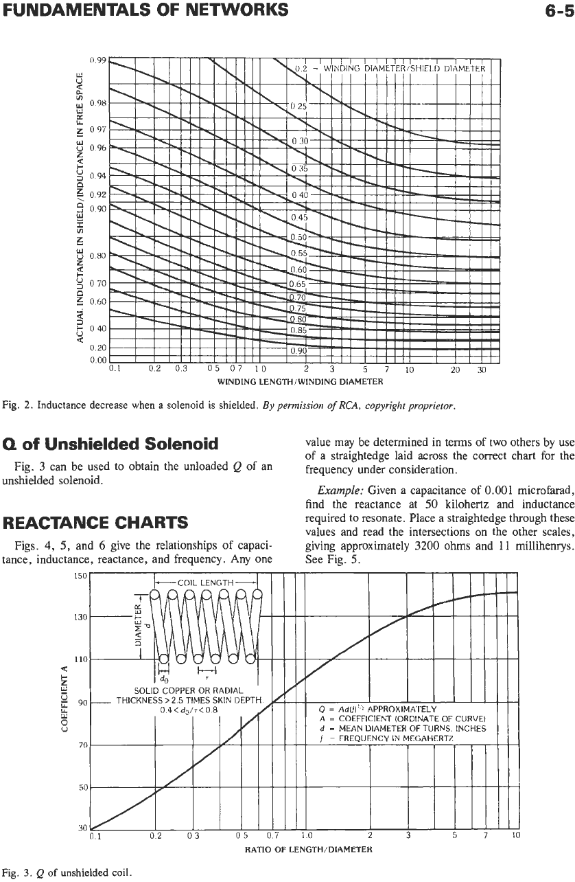
Q
of
Unshielded Solenoid
Fig.
3
can be used to obtain the unloaded
Q
of
an
unshielded solenoid.
REACTANCE CHARTS
required to resonate. Place a straightedge through these
values and read the intersections on the other scales.
Figs.
4,
5,
and
6
give the relationships of capaci-
tance, inductance, reactance, and frequency. Any one
giving approximately
3200
ohms and
11
millihenrys.
See Fig.
5.
150
COIL
LENGTH
1
I
Ill1
RATIO
OF
LENGTH/DIAMETER
Fig.
3.
Q
of
unshielded
coil.
6-6
REFERENCE DATA FOR ENGINEERS
INDUCTANCE
L
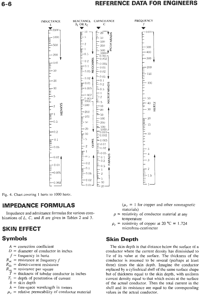
Fig.
4.
Chart covering
1
hertz to
1000
hertz.
REACTANCE CAPACITANCE
x,
OR
xc
C
v
v
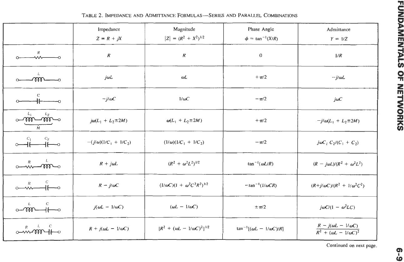
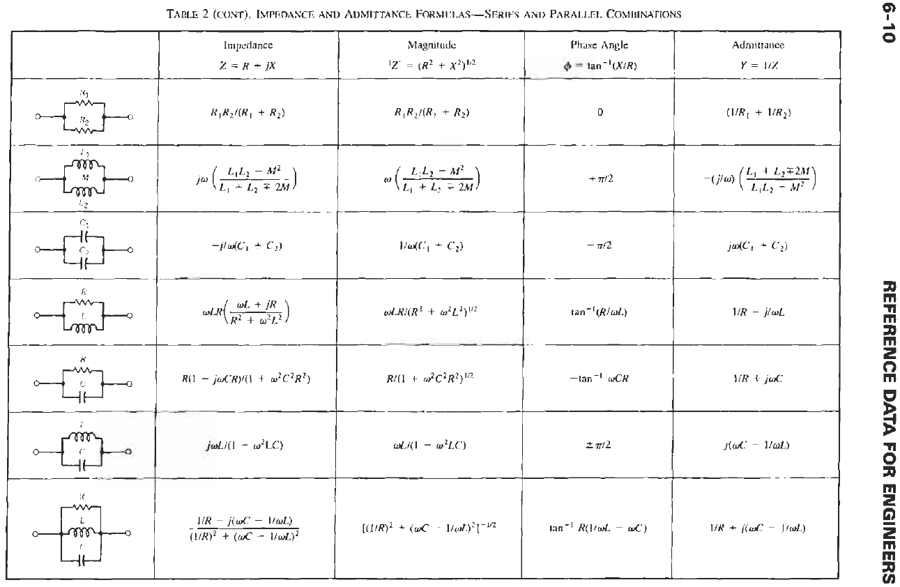
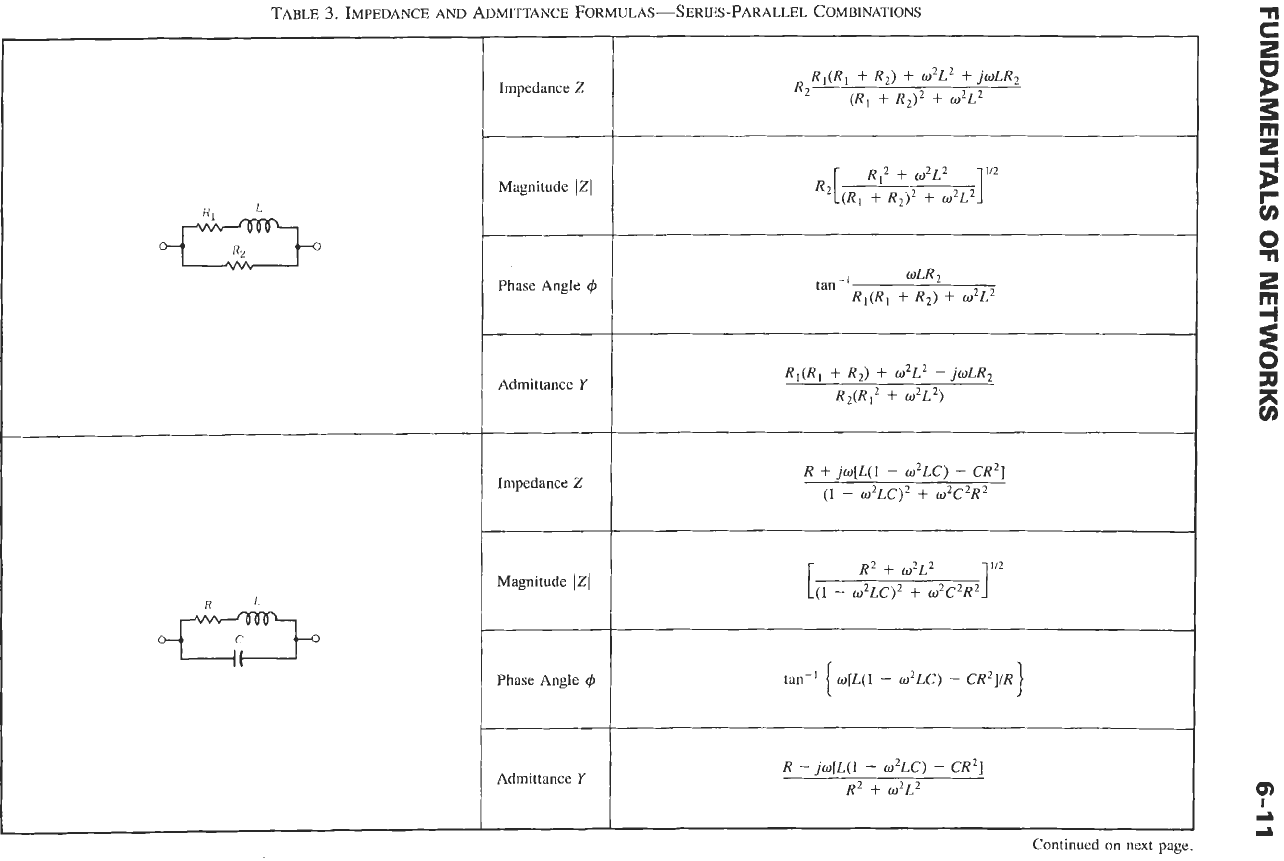
IMPEDANCE FORMULAS
Impedance and admittance formulas for various com-
binations of
L,
C,
and
R
are given in Tables
2
and
3.
SKIN
EFFECT
Sym
bok
A
=
correction coefficient
D
=
diameter of conductor in inches
f
=
frequency in hertz
R,
=
resistance at frequency
f
Rdc
=
direct-current resistance
R,,
=
resistance per square
T
=
thickness of tubular conductor in inches
TI
=
depth of penetration of current
6
=
skin depth
A
=
free-space wavelength in meters
pLI
=
relative permeability of conductor material
FREQUENCY
f
v
(pr
=
1 for copper and other nonmagnetic
materials)
temperature
microhms-centimeter
p
=
resistivity of conductor material at any
pc
=
resistivity
of
copper at
20
OC
=
1.724
Skin
Depth
The skin depth is that distance below the surface of a
conductor where the current density has diminished to
lle
of its value at the surface. The thickness
of
the
conductor is assumed to be several (perhaps at least
three) times the skin depth. Imagine the conductor
replaced by a cylindrical shell
of
the same surface shape
but of thickness equal to the skin depth, with uniform
current density equal to that which exists at the surface
of the actual conductor. Then the total current in the
shell and its resistance are equal to the corresponding
values in the actual conductor.
FUNDAMENTALS
OF
NETWORKS
6-7
INDUCTANCE REACTANCE CAPACITANCE
L
Xr
ORXC
C
v
v
10
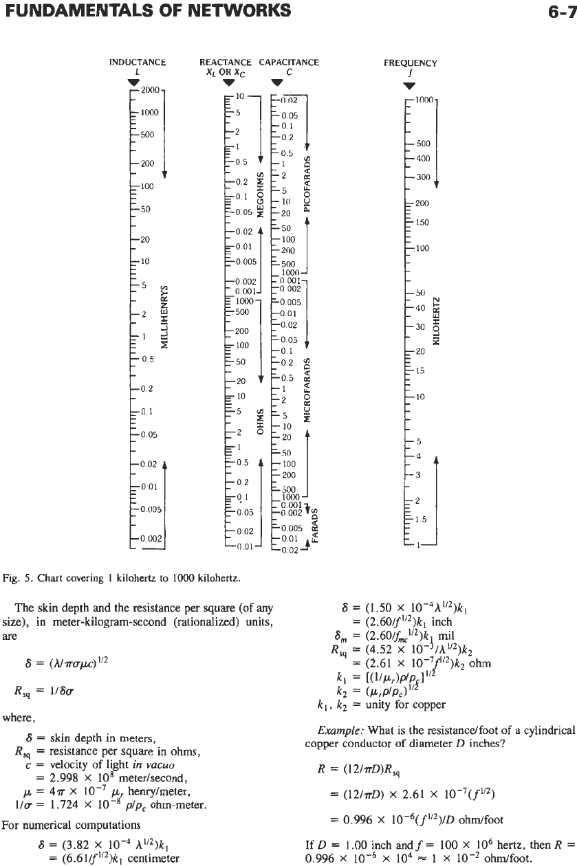
Fig.
5.
Chart covering
1
kilohertz
to
1000
kilohertz.
The skin depth and the resistance per square (of any
size), in meter-kilogram-second (rationalized) units,
are
R,,
=
116a
where,
S
=
skin depth in meters,
R,,
=
resistance per square in ohms,
c
=
velocity of light
in
vacuo
=
2.998
X
lo8
meterhecond,
p
=
4a
X
p
henrylmeter,
l/a
=
1.724
X
10-8rp/pc
ohm-meter.
For numerical computations
6
=
(3.82
X
A1”)k1
=
(6.61/f’/2)kl
centimeter
FREQUENCY
f
v
6
=
(1.50
X
10-4A1/2)kl
=
(2.60/f”2)kl
inch
6,
=
(2.60/f,’/2)k
mil
R,,
=
(4.52
X
10-
I
/h’/2)k2
=
(2.61
X
”’)k2
ohm
kl
=
[(1lPr)P1{/&I
Ill
k2
=
(P,P/Pc)
kl,
k2
=
unity for copper
Example:
What is the resistancelfoot of
a
cylindrical
copper conductor
of
diameter
D
inches?
R
=
(l2laD)R,,
=
(12/?rD)
X
2.61
X
10-7(f1’2)
=
0.996
X
10-6(f’/2)/D
ohdfoot
If
D
=
1.00
inch andf
=
100
X
lo6
hertz, then
R
=
0.996
X
X
lo4
=
1
X
ohdfoot.
6-8
REFERENCE
DATA
FOR ENGINEERS
REACTANCE
C
X,
OR
Xc
w
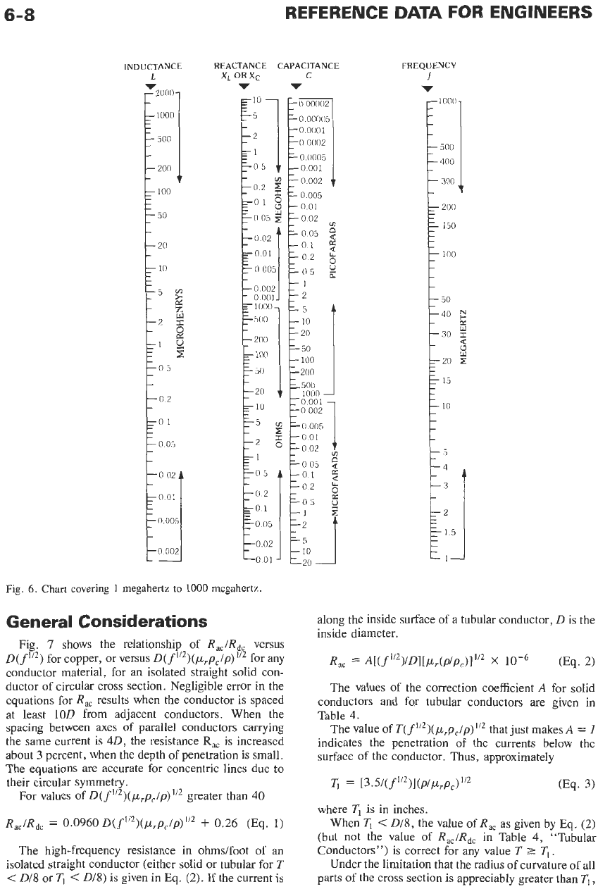
Fig.
6.
Chart covering
1
megahertz to
1000
megahertz.
General Considerations
Fig.
7
shows the relationship
of
Rac/Rd,
versus
D(fl”)
for copper, or versus
D(f”Z)(prp,/p)1’2
for any
conductor material, for
an
isolated straight solid con-
ductor of circular cross section. Negligible error in the
equations for
R,
results when the conductor is spaced
at least
1OD
from adjacent conductors. When the
spacing between axes
of
parallel conductors carrying
the same current is 40, the resistance
R,,
is increased
about
3
percent, when the depth
of
penetration is small.
The equations are accurate for concentric lines due to
their circular symmetry.
For values
of
D(f1’2)(prpc/p)112
greater than 40
Rac/Rdc
=
0.0960
D(f’/2)(prpc/p)”2
i-
0.26
(Eq.
1)
The high-frequency resistance in ohms/foot
of
an
isolated straight conductor (either solid or tubular for
T
<
Dl8
or
Ti
<
D/8)
is given in Eq.
(2).
If the current is
APACITANCE
C
v
0
00005
0
0001
0
0002
0
0005
0
002
0
005
-001
-
-002
in
=005
Q
-
-01
3
-05
-1
-2
-5
-
-
100
-200
s500
IO00
10
001
-0
002
-0
01
-005
$
-01
-002
in
102
I2
B
-
=05
0
10
20
FREQUENCY
f
v
1000
-
500
400
300
along the inside surface
of
a tubular conductor,
D
is the
inside diameter.
R,,
=
A[(f”2j/D][p,(p/p,)J”2
x
(Eq.
2)
The values of the correction coefficient
A
for solid
conductors and for tubular conductors are given in
Table
4.
The value of
T(f112)(prpc/p)1’2
that just makes
A
=
I
indicates the penetration of the currents below the
surface of the conductor. Thus, approximately
(Eq.
3)
~1
=
[3.5/(f112>~(~/~r~cj
’”
where
TI
is in inches.
When
Tl
<
018,
the value
of
R,,
as given by
Eq.
(2)
(but not the value of
Rac/Rdc
in Table 4, “Tubular
Conductors”) is correct for any value
T
2
Ti.
Under the limitation that the radius of curvature of all
parts
of
the cross section is appreciably greater than
T1,
w(LI
+
L,+2M)
+
T/2 -j/w(L,
+
L2f2M)
tan-’[(wL
-
l/wC)/R]
R
-
j(wL
-
lid)
R2
+
(wL
-
l/WC)’
TABLE
2.
IMPEDANCE AND
ADMITTANCE
FORMULAS-SERIES
AND PARALLEL COMBINATIONS
Magnitude
IZI
=
(R2
+
X2)‘”
Phase Angle
4
=
tan-’(X/R)
Admittance
Y
=
1/z
Impedance
Z=R+jX
I
R
0
1/R
L
-
jwL
OL
+
T/2
-j/wL
-j/WC
-
T/2
(l/O)(l/C,
+
UC’)
.
T/2
R
+
jwL
(R2
+
w2L2)”2
tan-’ (wL/R)
(R
-
jwL)/(R2
+
w2L2)
-
(lld)(l
+
w2C2R2)1‘2
-tan
-I
(IIWCR) (R+jloC)/(R2
f
1/w2C2)
I I
C
c--~(-J
I
R
-
j/wC
L
j(wL
-
l/WC) (wL
-
l/d)
f
T/2
[R2
+
(wL
-
l/WC)2]1’2
R
+
j(wL
-
l/WC)
1.
c
Continued on next page.
m
cb
TABLE
2
(CONT). IMPEDANCE
AND
ADMITTANCE
FORMULAS-SERIES
AND PARALLEL COMBINATIONS
--tan-'
oCR
1IR
+
joC
*
TI2
j(wC
-
l/wL)
Magnitude
IZI
=
(R2
+
X2)'l2
Impedance
Z
=
R
f
.jX
Y
=
l/Z
0
+
TI2
Jw
(Ll
L1L2
+
L,
-"'
+
2M
1
0
-j/w(C,
+
C2)
1/R
-
jlwL
tan-' R(l/wL
-
WC)
\/R
+
,I(&
-
l/oL)
1IR
-
j(wC
-
l/wL)
(1/R)2
+
(OC
-
l/oL)2
TABLE
3.
IMPEDANCE AND ADMITTANCE
FORMULAS-SERIES-PARALLEL
COMBINATIONS
Impedance
Z
Magnitude
121
Phase Angle
4
Admittance
Y
Impedance
2
Magnitude
IZl
Phase Angle
C#J
Admittance
Y
R,(R,
+
R,)
+
w2L2
+
jwLR2
(R,
+
R2)2
+
w2L2
R2
(R,
+
R2)’
+
w2L2
wLR~
R,(Rl
+
R2)
+
w2L2
tan-’
R,(R,
+
R,)
+
w2LZ
-jwLR2
R2(Rl2
+
w2L2)
R
+
jw[L(l
-
w2K)
-
CR2]
(1
-
w2LC)’
+
wZC2R2
1
R2
i-
w2L2
[(I
-
w2LC)’
+
w2C2R2
wlL(1
-
02LC)
-
CR2]/R
R
-
jolL(1
-
02LC)
-
CR2]
R2
+
w2L2
Continued on next page.
0
n