Middleton W.M. (ed.) Reference Data for Engineers: Radio, Electronics, Computer and Communications
Подождите немного. Документ загружается.

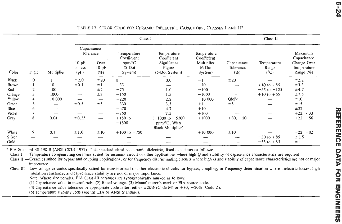
TABLE
17.
COLOR CODE
FOR
CERAMIC
DIELECTRIC
CAPACITORS, CLASSES
1
AND
II*
Class I Class
I1
Capacitance
Tolerance Temperature Temperature Temperature Maximum
Capacitance
10
pF Over PP&"C Significant Multiplier Capacitance Temperature Change
Over
or
less
10
pF (5-Dot Figure (6-Dot Tolerance Range Temperature
Coefficient Coefficient Coefficient
Color Digit Multiplier (pF)
("/.I
System) (6-Dot System) System)
(%)
("C) Range
(%)
Black
0
1
c2.0
t20
0
0.0
-1
r
20
-
*2.2
Brown
I
10
*o.
1
51
-33
-
-
10
-
+IO
to
+85
k3.3
Red
2
100
-
+2 -15
1
.o
-
100
-
-55
to +125 24.7
Orange
3
1000
-
t3
-
150
1.5
-
1000
-
+10
to +65
27.5
Yellow
4
10
000
-
-
-220
2.2
GMV
-
f
10
-
10
000
Green
5
-
f0.5
25
-330 3.3 +1
25
-
2
15
Blue 6
-
-
-
-
470 4.7
+
10
Violet 7
-
-
-
-750 7.5
+
100
+22
a
+22, -33
m
Gray 8 0.01
k0.25
-
+
150 to
(-
1000
to
-
5200
+
1000 +so, -20
-
+22, -56
n
m
a
0
m
U
importance.
B
-
-
- -
-
1500
ppm/"C, With
Black Multiplier)
e
3
6
e
White 9 0.1 tl.O
f
10
+
100 to
-750
-
f
10
-
+22, -82
+
10
000
Silver
-
Gold
*
EIA
Standard RS-198-B
(ANSI
C83.4-1972). This standard classifies ceramic dielectric, fixed capacitors as follows:
-
-
-
-
-
-
-
-30
to
+85
k1.5
-
-
- -
-
-
-
-55 to +85 t1
-
Class I -Temperature compensating ceramics suited for resonant circuit
or
other applications where high
Q
and stability of capacitance characteristics
are
required.
Class
I1
-Ceramics suited for bypass and coupling applications,
or
for frequency discriminating circuits where high
Q
and stability of capacitance characteristics are not of major
Class 111-Low-voltage ceramics specifically suited
for
transistorized
or
other electronic circuits
for
bypass, coupling,
or
frequency determination where dielectric losses, high
insulation resistance, and capacitance stability are not
of
major importance.
Note: Where size permits,
EIA
Class-I11 ceramics
are
typographically marked as follows:
(1)
Capacitance value in microfarads. (2) Rated voltage. (3) Manufacturer's mark
or
EIA
source code.
(4) Capacitance value tolerance
or
appropriate code letter; either +20% (Code M)
or
+SO, -20% (Code
Z).
(5)
Temperature stability code
(see
the
EIA
or
ANSI
Standard).
Jll
G)
E
m
rn
m
v)
MICA CAPACITORS
Mica capacitors fall within the classification of low
loss
and good capacitance stability. Mica is one of the
earliest dielectric materials used and has an unrivaled
combination of physical and electrical characteristics. It
is
of
mineral origin and, because of its monoclinic
structure, can be readily split into thin plates. It has
a
dielectric constant of about
6
(largely independent
of
frequency) together with a very low loss.
F
3!
-
EIA PREFIX
DM-DIPPED
2i
CASE SIZE
Construction
Mica capacitor constructions of the eyelet, molded,
bonded, and button styles have been largely replaced by
precision polystyrene, polypropylene, and polyester
plastic film capacitors and by ceramic capacitors. The
main surviving style is the dipped epoxy-coated radial-
leaded capacitor using a clamp-type silvered mica stack
with tin electrodes.
Applications
Their low temperature coefficient of capacitance and
good stability with temperature and frequency make
mica capacitors a good choice
for
critical precision
circuitry such as filter applications.
Type Designation
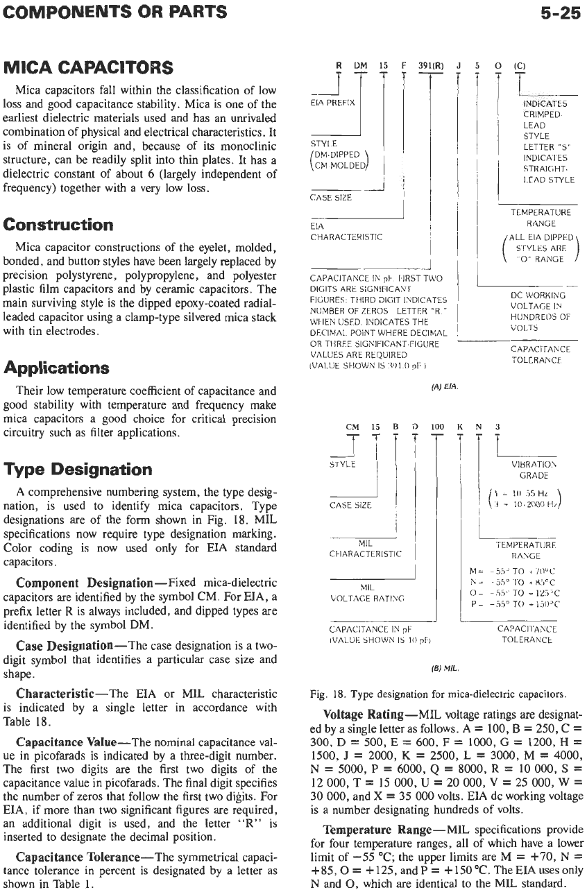
A comprehensive numbering system, the type desig-
nation, is used to identify mica capacitors. Type
designations are of the
form
shown in Fig.
18.
MIL
specifications now require type designation marking.
Color coding is now used only for EIA standard
capacitors.
Component
Designation-Fixed mica-dielectric
capacitors are identified by the symbol CM. For EIA, a
prefix letter
R
is always included, and dipped types are
identified by the symbol
DM.
Case
Designation-The case designation is a two-
digit symbol that identifies a particular case size and
shape.
Characteristic-The EIA or MIL characteristic
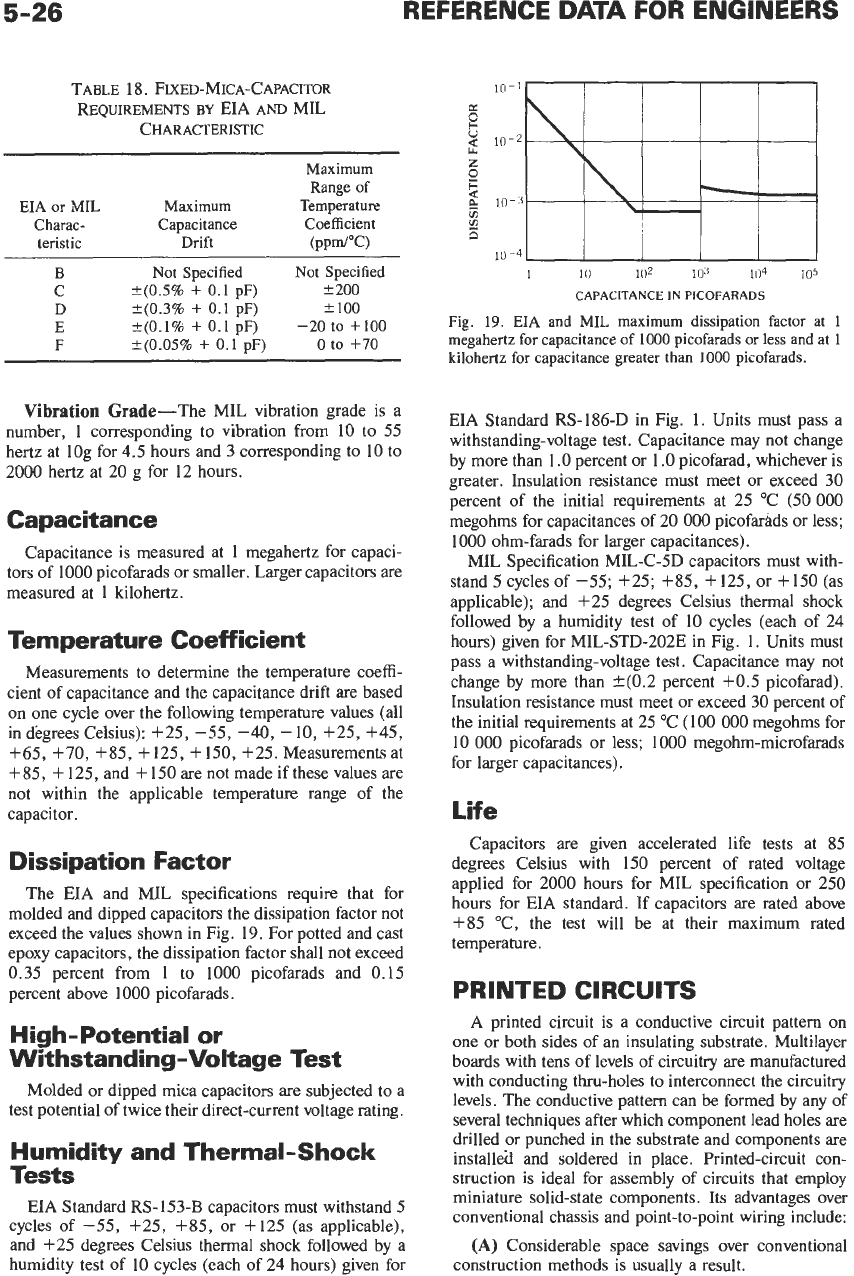
is indicated by a single letter in accordance with
Table 18.
Capacitance Value-The nominal capacitance val-
ue
in
picofarads is indicated by a three-digit number.
The first two digits are the first two digits of the
capacitance value in picofarads. The final digit specifies
the number of zeros that follow the first two digits. For
EIA, if more than two significant figures are required,
an additional digit is used, and the letter
"R"
is
inserted to designate the decimal position.
Capacitance Tolerance-The symmetrical capaci-
tance tolerance in percent is designated by a letter as
shown in Table
1.
EIA
CHARACTERISTIC
I
CAPACITANCE IN
pF.
1-IRST TWO
DIGITS ARE SIGNIFICANT
FIGURES. THIRD DIGIT INDICATES
NUMBER OF ZEROS LETTER "R."
WHEN USED, INDICATES THE
DECIMAL POINT WHERE DECIMAL
OR THREE SIGNIFICANT-FIGURE
VALUES ARE REQUIRED
(VALUE SHOWN
IS
391
0
pF
1
STYLE
"i
I1
i
MIL
CHARACTERISTIC
MIL
VOLTAGE RATING
(A)
EIA
CAPACITANCE
IN
pF
IVALUE SHOWN IS
10
pF1
5-25
5
0
(C)
t
INDICATES
CRIMPED-
LEAD
STYLE
LETTER
"S"
INDICATES
STRAIGHT-
LEAD STYLE
TEMPERATURE
RANGE
/ALL EIA DIPPED\
DC WORKING
VOLTAGE
IN
HUNDREDSOF
VOLTS
CAPACITAhCE
TOLERANCE
3
-L
TEMPERATURE
RANGE
M-
-55"
TO
+71)"C
N=
--
3So
TO +85'C
O=
-5.5'
TO
T
125'C
P
=
-
55'
TO
+
15OoC
CAPACITANCE
TOLERANCE
(6)
MIL.
Fig.
18.
Type designation
for
mica-dielectric capacitors.
Voltage Rating-MIL voltage ratings are designat-
ed by a single letter as follows. A
=
100,
B
=
250,
C
=
300,
D
=
500,
E
=
600,
F
=
1000,
G
=
1200,
H
=
1500,
J
=
2000,
K
=
2500,
L
=
3000,
M
=
4000,
N
=
5000,
P
=
6000,
Q
=
8000,
R
=
10
000,
S
=
12
000,
T
=
15
000,
U
=
20
000,
V
=
25
000,
W
=
30
000,
and
X
=
35
000
volts. EIA dc working voltage
is a number designating hundreds
of
volts.
Temperature Range-MIL specifications provide
for four temperature ranges, all
of
which have a lower
limit of
-55
"C;
the upper limits are M
=
+70,
N
=
+85,0
=
+
125,
and
P
=
+
150
"C.
The EIA uses only
N
and
0,
which are identical to the MIL standard.
5-26
REFERENCE DATA FOR ENGINEERS
TABLE
18.
FIXED-MICA-CAPACITOR
REQUIREMENTS
BY
EIA
AND
MIL
CHARACTERISTIC
Maximum
Range
of
EIA
or MIL Maximum Temperature
Charac- Capacitance Coefficient
teristic
Drift (PP&"C)
C
?(OS%
+
0.1
pF)
?
200
D
*(0.3%
+
0.1
pF)
+.
100
B
Not
Specified
Not
Specified
E
k(O.196
+
0.1
pF)
-20
to
+lo0
F
?(0.05%
+
0.1
pF)
0
to
+70
Vibration Grade-The MIL vibration grade is a
number,
1
corresponding to vibration from
10
to 55
hertz at log for 4.5 hours and
3
corresponding to 10 to
2000 hertz at 20
g
for 12 hours.
Capacitance
Capacitance is measured at
1
megahertz for capaci-
tors of 1000 picofarads or smaller. Larger capacitors are
measured at
1
kilohertz.
Temperature Coefficient
Measurements to determine the temperature coeffi-
cient of capacitance and the capacitance drift are based
on one cycle over the following temperature values (all
indegrees Celsius): +25, -55, -40,
-10,
+25, +45,
+65,
+70,
+85, +125, +150, +25. Measurements at
+
85,
+
125, and
+
150
are not made if these values are
not within the applicable temperature range of the
capacitor.
Dissipation Factor
The EIA and MIL specifications require that for
molded and dipped capacitors the dissipation factor not
exceed the values shown in Fig.
19.
For potted and cast
epoxy capacitors, the dissipation factor shall not exceed
0.35 percent from
1
to
1000 picofarads and 0.15
percent above 1000 picofarads.
High-Potential or
Withstanding-Voltage Test
Molded
or
dipped mica capacitors are subjected to a
test potential
of
twice their direct-current voltage rating.
Humidity and Thermal-Shock
Tests
EIA Standard RS-153-B capacitors
must
withstand
5
cycles of -55, +25, f85, or +125 (as applicable),
and f25 degrees Celsius thermal shock followed by a
humidity test of
10
cycles (each of 24 hours) given for
1
10
102
1ti3
104
105
CAPACITANCE IN PICOFARADS
Fig.
19.
EIA
and MIL maximum dissipation factor
at
1
megahertz for capacitance
of
1000
picofarads or
less
and at
1
kilohertz
for
capacitance greater than
1000
picofarads.
EIA Standard RS-186-D in Fig.
1.
Units must
pass
a
withstanding-voltage test. Capacitance may not change
by more than 1
.O
percent or
1
.O
picofarad, whichever is
greater. Insulation resistance must meet or exceed 30
percent of the initial requirements at 25 "C (50
000
megohms for capacitances of 20
000
picofarads or less;
1000 ohm-farads for larger capacitances).
MIL Specification MIL-C-5D capacitors must with-
stand
5
cycles of -55; +25; $85, f125, or +150 (as
applicable); and +25 degrees Celsius thermal shock
followed by a humidity test of 10 cycles (each of 24
hours) given for MIL-STD-202E in Fig.
1.
Units must
pass a withstanding-voltage test. Capacitance may not
change by more than k(0.2 percent +0.5 picofarad).
Insulation resistance must meet or exceed
30
percent of
the initial requirements at 25 "C (100
000
megohms for
10
000
picofarads or less;
1000
megohm-microfarads
for larger capacitances).
Life
Capacitors are given accelerated life tests at
85
degrees Celsius with
150
percent of rated voltage
applied for
2000
hours for MIL specification
or
250
hours for EIA standard. If capacitors are rated above
$85
"C, the test will be at their maximum rated
temperature.
PRINTED CIRCUITS
A
printed circuit is a conductive circuit pattern
on
one or both sides of an insulating substrate. Multilayer
boards with tens of levels of circuitry are manufactured
with conducting thru-holes to interconnect the circuitry
levels. The conductive pattern can be formed by any of
several techniques after which component lead holes are
drilled or punched in the substrate and components are
installed and soldered in place. Printed-circuit con-
struction is ideal for assembly of circuits that employ
miniature solid-state components. Its advantages over
conventional chassis and point-to-point wiring include:
(A)
Considerable space savings over conventional
construction methods is usually a result.
COMPONENTS OR PARTS
5-27
(B)
A complex circuit may be modularized by using
several small printed circuits instead of a single larger
one. Modularization simplifies troubleshooting, circuit
modification, and mechanical assembly in an enclosure.
(C)
Soldering of component leads may be accom-
plished in an orderly sequence by hand or by dip or
wave soldering.
(D)
A more uniform product is produced because
wiring errors are eliminated and because distributed
capacitances
are
constant from one production unit
to
another.
(E)
The printed-circuit method of construction
lends itself to automatic assembly and testing.
(F)
Using appropriate base metals, flexible cables or
flexible circuits can be built.
(G)
By using several layers of circuits (in proper
registry) in a sandwich construction, with the conduc-
tors separated by insulating layers, relatively complex
wiring can be provide.
Printed-Circuit Base Materials
Rigid printed-circuit base materials
are
available in
thicknesses varying from
1/64
to
1/2
inch. The important
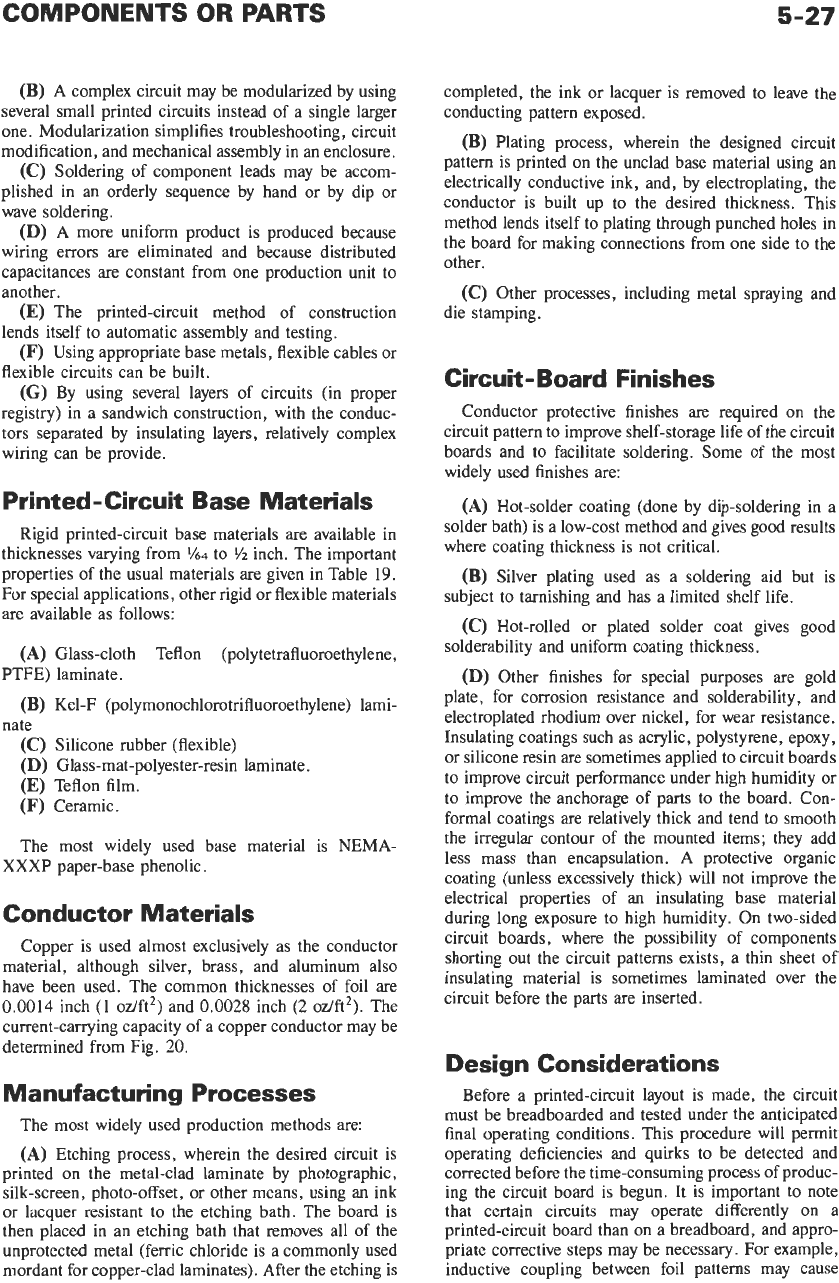
properties of the usual materials
are
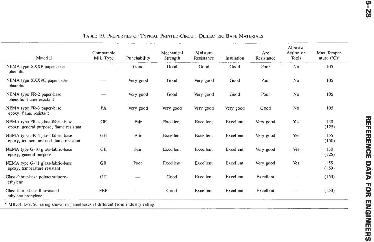
given in Table
19.
For
special applications, other rigid or flexible materials
are available as follows:
(A)
Glass-cloth Teflon
(poiytetrafluoroethylene,
(B)
Kel-F
(polymonochlorotrifluoroethylene)
lami-
(C)
Silicone rubber (flexible)
(D)
Glass-mat-polyester-resin laminate.
(E)
Teflon film.
(F)
Ceramic.
The most widely used base material is NEMA-
PTFE) laminate.
nate
XXXP paper-base phenolic.
Conductor Materials
Copper is used almost exclusively as the conductor
material, although silver, brass, and aluminum also
have been used. The common thicknesses of foil are
0.0014
inch (1 oz/ft2) and
0.0028
inch
(2
oz/ft2). The
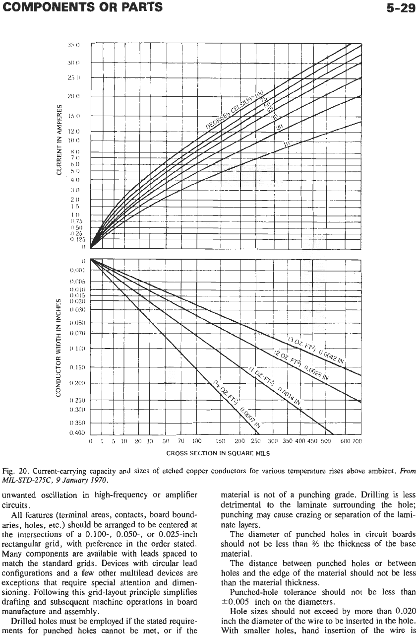
current-carrying capacity of a copper conductor may be
determined from Fig.
20.
Manufacturing Processes
The most widely used production methods are:
(A)
Etching process, wherein the desired circuit is
printed on the metal-clad laminate by photographic,
silk-screen, photo-offset, or other means, using an ink
or lacquer resistant to the etching bath. The board is
then placed in an etching bath that removes all of the
unprotected metal (ferric chloride is a commonly used
mordant for copper-clad laminates). After the etching
is
completed, the ink or lacquer is removed
to
leave the
conducting pattern exposed.
(B)
Plating process, wherein the designed circuit
pattern is printed on the unclad base material using an
electrically conductive ink, and, by electroplating, the
conductor
is
built up to the desired thickness. This
method lends itself to plating through punched holes in
the board for making connections from one side to the
other.
(C)
Other processes, including metal spraying and
die stamping.
Circuit- Board Finishes
Conductor protective finishes are required on the
circuit pattern to improve shelf-storage life of the circuit
boards and to facilitate soldering. Some of the most
widely used finishes are:
(A)
Hot-solder coating (done by dip-soldering in a
solder bath) is a low-cost method and gives good results
where coating thickness is not critical.
(B)
Silver plating used as a soldering aid but is
subject to tarnishing and has a limited shelf life.
(C)
Hot-rolled or plated solder coat gives good
solderability and uniform coating thickness.
(D)
Other finishes for special purposes are gold
plate, for corrosion resistance and solderability, and
electroplated rhodium over nickel, for wear resistance.
Insulating coatings such as acrylic, polystyrene, epoxy,
or silicone resin are sometimes applied to circuit boards
to improve circuit performance under high humidity or
to improve the anchorage of parts to the board. Con-
formal coatings are relatively thick and tend to smooth
the irregular contour of the mounted items; they add
less mass than encapsulation. A protective organic
coating (unless excessively thick) will not improve the
electrical properties of an insulating base material
during long exposure to high humidity. On two-sided
circuit boards, where the possibility of components
shorting out the circuit patterns exists, a thin sheet of
insulating material is sometimes laminated over the
circuit before the parts
are
inserted.
Design Considerations
Before a printed-circuit layout is made, the circuit
must be breadboarded and tested under the anticipated
final operating conditions. This procedure will permit
operating deficiencies and quirks to be detected and
corrected before the time-consuming process of produc-
ing the circuit board
is
begun. It is important to note
that certain circuits may operate differently
on
a
printed-circuit board than on a breadboard, and appro-
priate corrective steps may be necessary. For example,
inductive coupling between foil patterns may cause
TABLE
19.
PROPERTIES
OF
TYPICAL
PRINTED-CIRCUIT
DIELECTRIC
BASE
MATERIALS
Abrasive
Comparable Mechanical Moisture Arc Action on Max Temper-
Material MIL Type Punchability Strength Resistance Insulation Resistance Tools ature
("C)*
NEMA type XXXP paper-base
NEMA type XXXPC paper-base
phenolic
phenolic
phenolic, flame resistant
epoxy, flame resistant
NEMA type FR-2 paper-base
NEMA type FR-3 paper-base
NEMA type FR-4 glass-fabric-base
epoxy, general purpose, flame resistant
NEMA type FR-5 glass-fabric-base
epoxy, temperature and flame resistant
epoxy, general purpose
epoxy, temperature resistant
ethylene
NEMA type
(3-10
glass-fabric-base
NEMA type
G-
11 glass-fabric-base
Glass-fabric-base polytetrafluoro-
Glass-fabric-base fluorinated
ethylene propylene
-
-
-
PX
GF
GH
GE
GB
GT
FEP
Good
Very good
Very good
Very good
Fair
Fair
Fair
Poor
-
-
Good
Good
Good
Very good
Excellent
Excellent
Excellent
Excellent
Good
Good
Good
Very good
Very good
Very good
Excellent
Excellent
Excellent
Excellent
Excellent
Excellent
Good
Good
Good
Very good
Excellent
Excellent
Excellent
Excellent
Excellent
Excellent
Poor
Poor
Poor
Good
Very good
Very good
Very good
Very good
Excellent
Excellent
No
No
No
No
Yes
Yes
Yes
Yes
-
-
*
MIL-STD-275C rating shown in parentheses if different from industry rating
COMPONENTS OR PARTS
5-29
1
(1
I1
75
I1
50
(1
2s
0.125
0
0
0
Olll
0
O(1S
0
010
0
015
r
I1
0.30
0
y
0
020
z
0
OS(1
E
8
0
iso
2
0
200
0
070
z
3
(1
100
K
3
0
ir
0
250
0
300
0350
.
0
400
0
1
S
10
20
30
50 70 100
IS0
200
250
300
350 400 450 500 600
700
CROSS SECTION
IN
SQUARE
MILS
Fig.
20.
Current-carrying capacity and
sizes
of
etched copper conductors for various temperature rises above ambient.
From
MIL-STD-275C, 9
January
1970.
unwanted oscillation in high-frequency or amplifier
circuits.
All features (terminal areas, contacts, board bound-
aries, holes, etc.) should be arranged to be centered at
the intersections
of
a
0.100-,
0.050-,
or 0.025-inch
rectangular grid, with preference in the order stated.
Many components
are
available with leads spaced to
match the standard grids. Devices with circular lead
configurations and a few other multilead devices are
exceptions that require special attention and dimen-
sioning. Following this grid-layout principle simplifies
drafting and subsequent machine operations in board
manufacture and assembly.
Drilled holes must be employed if the stated require-
ments for punched holes cannot be met, or if the
material is not of a punching grade. Drilling
is
less
detrimental to the laminate surrounding the hole;
punching may cause crazing
or
separation of the lami-
nate layers.
The diameter
of
punched holes in circuit boards
should not be less than
%
the thickness of the base
material.
The distance between punched holes or between
holes and the edge of the material should not be less
than the material thickness.
Punched-hole tolerance should not be less than
20.005
inch on the diameters.
Hole sizes should not exceed by more than
0.020
inch the diameter of the wire to be inserted in the hole.
With smaller holes, hand insertion of the wire is
difficult. Machine insertion requires the larger allow-
ance. Clinching of the lead is desirable if the clearance
is
larger.
Tolerances with respect to the true-grid location for
terminal area centers and for locating edges of boards or
other locating features (datums) should not exceed on
the board:
0.014
inch diameter for conductor widths
and spacings above 0.031 inch;
0.010
inch diameter for
conductor widths and spacings
0.010
to 0.031 inch,
inclusive. Tolerances on other dimensions (except con-
ductor widths and spacings) may be larger. Closer
tolerances may be needed if machine insertion is
required.
Terminal area diameters should be at least (A) 0.020
inch larger than the diameter of the flange or projection
of the flange on eyelets
or
standoff terminals, or the
diameter of a plated-through hole, and
(B)
0.040
inch
larger than the diameter of an unsupported hole. Since
the terminal area should be unbroken around the
finished hole, the diameter should be further increased
over the above minimum to allow for the permitted
hole-position tolerance.
Conductor widths should be adequate for the current
carried. See Fig. 20. For a given conductor-width and
copper-thickness intersection, proceed vertically to the
allowable temperature-rise line and then horizontally to
the
left to determine the permissible current. An
additional 15% derating is recommended for board
thicknesses of
1/32
inch or less, or for conductors thicker
than
0.004
inch
(3
oz).
The normal ambient tempera-
ture surrounding the board plus the allowable tempera-
ture rise should not exceed the maximum safe operating
temperature of the laminate. For ordinary work, copper
conductor widths of
0.060
inch are convenient; with
high-grade technique (extra cost), conductor widths as
small
as
0.010
inch can be readily produced.
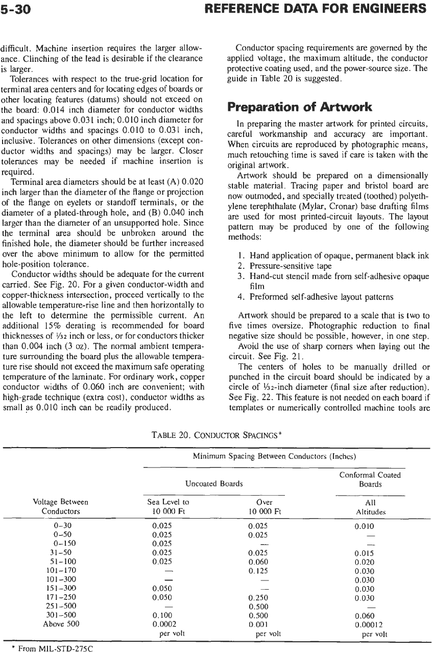
Conductor spacing requirements are governed by the
applied voltage, the maximum altitude, the conductor
protective coating used, and the power-source size. The
guide in Table
20
is suggested.
Preparation
of
Artwork
In preparing the master artwork for printed circuits,
careful workmanship and accuracy are important.
When circuits are reproduced by photographic means,
much retouching time is saved if care is taken with the
original artwork.
Artwork should be prepared on a dimensionally
stable material. Tracing paper and bristol board are
now outmoded, and specially treated (toothed) polyeth-
ylene terephthalate (Mylar, Cronar) base drafting films
are used for most printed-circuit layouts. The layout
pattern may be produced by one of the following
methods:
1.
Hand application of opaque, permanent black ink
2. Pressure-sensitive tape
3. Hand-cut stencil made from self-adhesive opaque
4.
Preformed self-adhesive layout patterns
Artwork should be prepared to a scale that is two to
five times oversize. Photographic reduction to final
negative size should be possible, however, in one step.
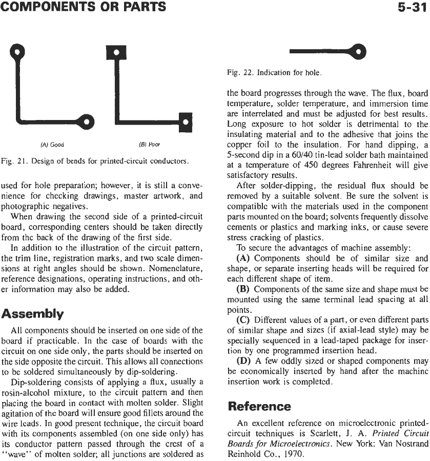
Avoid the use of sharp comers when laying out the
circuit. See Fig. 21.
The centers of holes
to
be manually drilled or
punched in the circuit board should be indicated by a
circle of %-inch diameter (final size after reduction).
See Fig.
22.
This feature is not needed on each board if
templates or numerically controlled machine tools are
film
TABLE 20. CONDUCTOR SPACINGS*
Minimum Spacing Between Conductors (Inches)
Conformal Coated
Uncoated Boards Boards
Voltage Between
Sea Level
to
Over
All
Conductors
10
000
Ft
10 000
Ft
Altitudes
0-30 0.025
0.025
0.010
0-50
0.025
0.025
-
0-150
0.025
-
3
1-50
0.025 0.025 0.015
51-100
0.025
0.060
0.020
101-170
-
0.125 0.030
-
0.030
101-300
-
15 1-300
0.050
-
0.030
171-250
0.050
0.250
0.030
25
1-500
-
0.500
-
30
1-500
0.100
0.500
0.060
Above
500
0.0002
0.001
0.000
12
-
per volt per volt
per
volt
*
From
MIL-STD-275C
5-31
Fig.
22.
Indication for hole.
(AI
Good
(E)
Poor
Fig.
21.
Design
of
bends for printed-circuit conductors
used for hole preparation; however, it is still a conve-
nience for checking drawings, master artwork, and
photographic negatives.
When drawing the second side
of
a printed-circuit
board, corresponding centers should be taken directly
from the back of the drawing
of
the first side.
In addition to the illustration
of
the circuit pattern,
the trim line, registration marks, and two scale dimen-
sions at right angles should be shown. Nomenclature,
reference designations, operating instructions, and oth-
er information may also be added.
Assembly
All components should be inserted on one side of the
board if practicable. In the case
of
boards with the
circuit on one side only, the parts should be inserted on
the side opposite the circuit. This allows all connections
to be soldered simultaneously by dip-soldering
.
Dip-soldering consists
of
applying a flux, usually a
rosin-alcohol mixture, to the circuit pattern and then
placing the board in contact with molten solder. Slight
agitation of the board will ensure good fillets around the
wire leads. In good present technique, the circuit board
with its components assembled
(on
one side only) has
its conductor pattern passed through the crest of a
“wave” of molten solder; all junctions are soldered as
the board progresses through the wave. The flux, board
temperature, solder temperature, and immersion time
are interrelated and must be adjusted for best results.
Long exposure to hot solder is detrimental
to
the
insulating material and to the adhesive that joins the
copper foil to the insulation. For hand dipping, a
5-second dip in a
60/40
tin-lead solder bath maintained
at a temperature of
450
degrees Fahrenheit will give
satisfactory results.
After solder-dipping, the residual flux should be
removed by a suitable solvent. Be sure the solvent is
compatible with the materials used in the component
parts mounted on the board; solvents frequently dissolve
cements or plastics and marking inks, or cause severe
stress cracking of plastics.
To
secure the advantages of machine assembly:
(A)
Components should be of similar size and
shape, or separate inserting heads will be required for
each different shape of item.
(B)
Components
of
the same size and shape must be
mounted using the same terminal lead spacing at all
points.
(C)
Different values of a part, or even different parts
of similar shape and sizes (if axial-lead style) may be
specially sequenced in a lead-taped package for inser-
tion by one programmed insertion head.
(D)
A few oddly sized or shaped components may
be economically inserted by hand after the machine
insertion work is completed.
Reference
An excellent reference on microelectronic printed-
circuit techniques is Scarlett,
J.
A.
Printed Circuit
Boards
for
Microelectronics.
New York: Van Nostrand
Reinhold Co.,
1970.
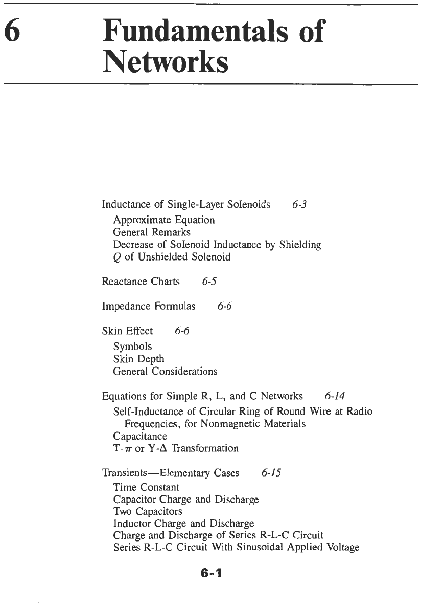
6
Fundamentals
of
Networks
Inductance of Single-Layer Solenoids
6-3
Approximate Equation
General Remarks
Decrease of Solenoid Inductance by Shielding
Q
of Unshielded Solenoid
Reactance Charts
6-5
Impedance Formulas
6-6
Skin Effect
6-6
Symbols
Skin Depth
General Considerations
Equations for Simple R, L, and C Networks
Frequencies, for Nonmagnetic Materials
6-14
Self-Inductance of Circular Ring of Round Wire at Radio
Capacitance
T-T
or
Y-A
Transformation
Transients-Elementary Cases
6-15
Time Constant
Capacitor Charge and Discharge
Two Capacitors
Inductor Charge and Discharge
Charge and Discharge
of
Series R-L-C Circuit
Series R-L-C Circuit With Sinusoidal Applied Voltage
6-
1
