Middleton W.M. (ed.) Reference Data for Engineers: Radio, Electronics, Computer and Communications
Подождите немного. Документ загружается.

26-6
REFERENCE
DATA
FOR
ENGINEERS
$10
55
$2
51
c
2
$050
0
YEAR
OF
SERVICE
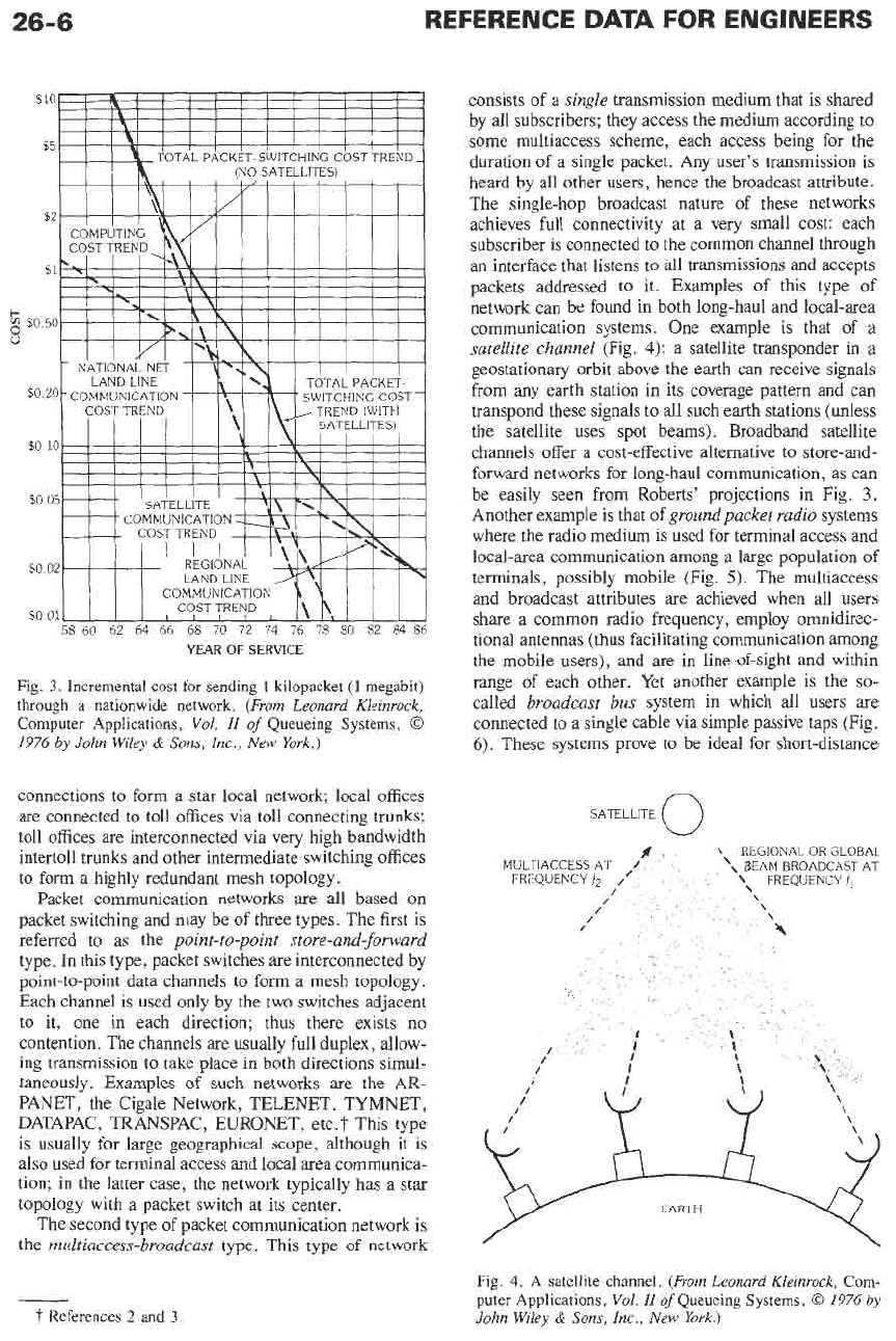
Fig.
3.
Incremental cost for sending
1
kilopacket
(1
megabit)
through
a
nationwide network.
(From Leonard Kleinrock,
Computer
Applications,
Vol.
II
of
Queueing Systems,
0
1976
by
John Wiley
&
Sons, Inc., New York.)
connections to form a star local network; local offices
are connected to toll ofices via toll connecting trunks;
toll offices are interconnected via very high bandwidth
intertoll trunks and other intermediate switching offices
to form a highly redundant mesh topology.
Packet communication networks are all based on
packet switching and may be of three types. The first is
referred to as the
point-to-point store-and-forward
type. In this type, packet switches are interconnected by
point-to-point data channels to form a mesh topology.
Each channel is used only by the two switches adjacent
to it, one in each direction; thus there exists no
contention. The channels are usually full duplex, allow-
ing transmission to take place in both directions simul-
taneously. Examples of such networks are the AR-
PANET, the Cigale Network, TELENET, TYMNET,
DATAPAC
,
TRANSPAC
,
EURONET, etc.
t
This type
is
usually
for
large geographical scope, although it is
also used for terminal access and local area communica-
tion; in the latter case, the network typically has a star
topology with a packet switch at its center.
The second type of packet communication network is
the
multiaccess-broadcast
type. This type of network
-
I-
References
2
and
3
consists of a
single
transmission medium that is shared
by all subscribers; they access the medium according to
some multiaccess scheme, each access being for the
duration of a single packet. Any user’s transmission is
heard by all other users, hence the broadcast attribute.
The single-hop broadcast nature
of
these networks
achieves full connectivity at a very small cost: each
subscriber
is
connected to the common channel through
an interface that listens to all transmissions and accepts
packets addressed to it. Examples of this type
of
network can be found in both long-haul and local-area
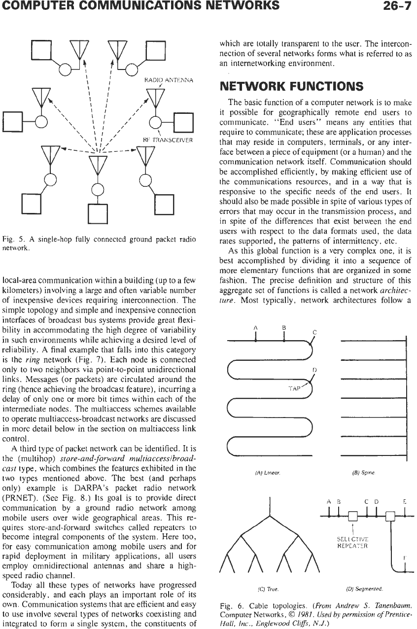
communication systems. One example is that of a
satellite channel
(Fig.
4):
a satellite transponder in
a
geostationary orbit above the earth can receive signals
from any earth station in its coverage pattern and can
transpond these signals to all such earth stations (unless
the satellite uses spot beams). Broadband satellite
channels offer a cost-effective alternative to store-and-
forward networks for long-haul communication, as can
be easily seen from Roberts’ projections in Fig.
3.
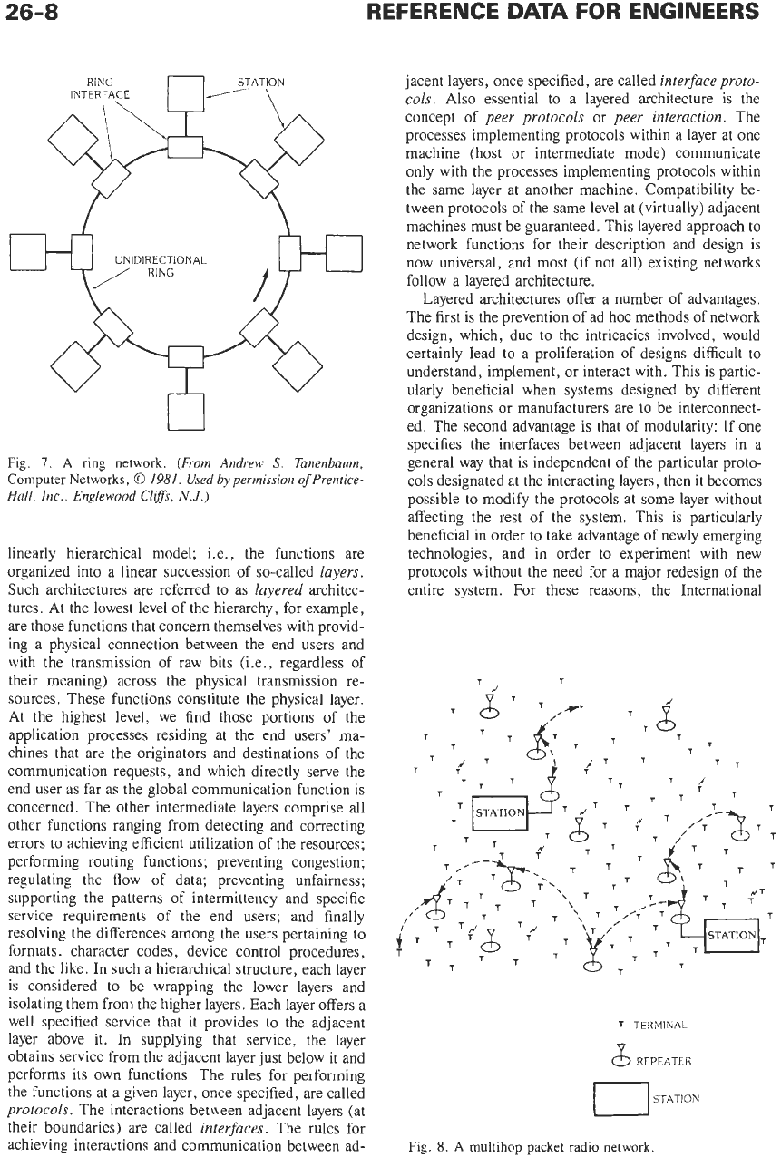
Another example is that of
groundpacket radio
systems
where the radio medium is used for terminal access and
local-area communication among a large population
of
terminals, possibly mobile (Fig.
5).
The multiaccess
and broadcast attributes are achieved when all users
share a common radio frequency, employ omnidirec-
tional antennas
(thus
facilitating communication among
the mobile users), and are in line-of-sight and within
range of each other. Yet another example
is
the
so-
called
broadcast
bus
system in which all users are
connected to a single cable via simple passive taps (Fig.
6).
These systems prove to be ideal for short-distance
Fig.
4.
A
satellite
channel.
(From Leonard Kleinrock,
Com-
puter
Applications,
VoZ.
IZ
ofQueueing
Systems,
0
1976
by
John Wiley
&
Sons, Inc., New York.)
COMPUTER COMMUNICATIONS NETWORKS
26-7
B
U
Fig.
5.
A
single-hop
fully
connected
ground packet radio
network.
local-area communication within a building (up to a few
kilometers) involving a large and often variable number
of inexpensive devices requiring interconnection. The
simple topology and simple and inexpensive connection
interfaces of broadcast bus systems provide great flexi-
bility in accommodating the high degree of variability
in such environments while achieving a desired level of
reliability.
A
final example that falls into this category
is the
ring
network (Fig.
7).
Each node
is
connected
only to two neighbors via point-to-point unidirectional
links. Messages (or packets) are circulated around the
ring (hence achieving the broadcast feature), incurring a
delay of only one or more bit times within each of the
intermediate nodes. The multiaccess schemes available
to operate multiaccess-broadcast networks are discussed
in more detail below in the section on multiaccess link
control.
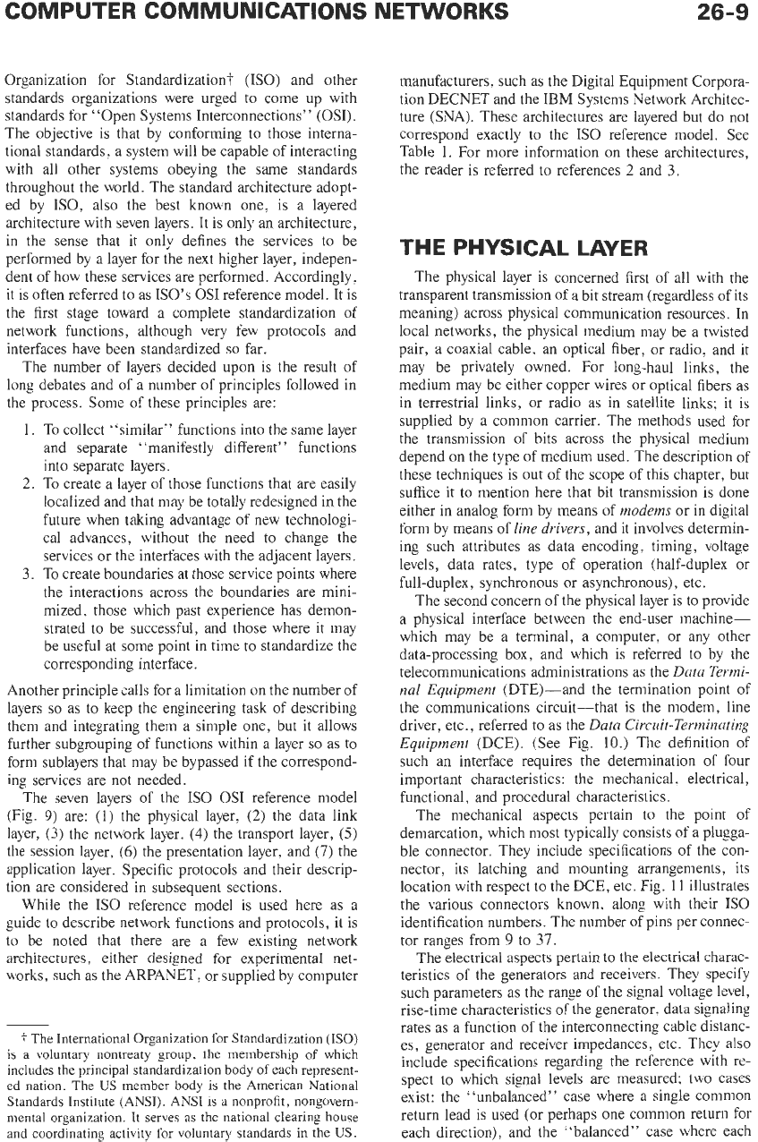
A
third type of packet network can be identified. It
is
the (multihop)
store-and-forward multiaccessibroad-
cast
type, which combines the features exhibited in the
two types mentioned above. The best (and perhaps
only) example is
DARPA’s
packet radio network
(PRNET). (See Fig.
8.)
Its
goal is to provide direct
communication by a ground radio network among
mobile users over wide geographical areas. This re-
quires store-and-forward switches called repeaters
to
become integral components
of
the system. Here too,
for easy communication among mobile users and for
rapid deployment in military applications, all users
employ omnidirectional antennas and share a high-
speed radio channel.
Today all these types of networks have progressed
considerably, and each plays an important role of its
own. Communication systems that are efficient and easy
to use involve several types of networks coexisting and
integrated to form a single system, the constituents of
which are totally transparent to the user. The intercon-
nection of several networks forms what is referred to as
an internetworking environment.
NETWORK FUNCTIONS
The basic function of a computer network
is
to
make
it possible for geographically remote end users to
communicate. “End users” means any entities that
require to communicate; these are application processes
that may reside in computers, terminals, or any inter-
face between a piece of equipment (or a human) and the
communication network itself. Communication should
be accomplished efficiently, by making efficient use of
the communications resources, and in a way that
is
responsive to the specific needs of the end users. It
should also be made possible in spite of various types of
errors that may occur in the transmission process, and
in spite of the differences that exist between the end
users with respect to the data formats used, the data
rates supported, the patterns of intermittency, etc.
As
this global function is a very complex one, it is
best accomplished by dividing
it
into a sequence of
more elementary functions that are organized in some
fashion. The precise definition and structure of this
aggregate set of functions
is
called a network
architec-
ture.
Most typically, network architectures follow a
(A)
Llnear.
(BJ
Spine.
I
AB
CD
E
(Cl
Tree
(Dl
Segmented
Fig.
6.
Cable
topologies.
(From Andrew
5’.
Tanenbaum,
Computer
Networks,
0
1981.
Used by permission
of
Prentice-
Hall, Inc., Englewood
Cliffs,
N.J.)
26-8
REFERENCE
DATA
FOR ENGINEERS
U
Fig.
7.
A
ring
network.
(From Andrew
S.
Tanenbaum,
Computer
Networks,
0
1981.
Used
by
permission
of
Prentice-
Hall,
Inc.,
Englewood
Clirs,
N.J.)
linearly hierarchical model; i.e., the functions are
organized into a linear succession of so-called
layers.
Such architectures are referred to as
layered
architec-
tures. At the lowest level of the hierarchy, for example,
are those functions that concern themselves with provid-
ing a physical connection between the end users and
with the transmission of raw bits (Le., regardless of
their meaning) across the physical transmission re-
sources. These functions constitute the physical layer.
At the highest level, we find those portions of the
application processes residing at the end users' ma-
chines that are the originators and destinations of the
communication requests, and which directly serve the
end user as far as the global communication function
is
concerned. The other intermediate layers comprise all
other functions ranging from detecting and correcting
errors to achieving efficient utilization of the resources;
performing routing functions; preventing congestion;
regulating the flow of data; preventing unfairness;
supporting the patterns of intermittency and specific
service requirements
of
the end users; and finally
resolving the differences among the users pertaining
to
formats, character codes, device control procedures,
and the like. In such a hierarchical structure, each layer
is considered to be wrapping the lower layers and
isolating them from the higher layers. Each layer offers a
well specified service that it provides to the adjacent
layer above it. In supplying that service, the layer
obtains service from the adjacent layer just below it and
performs its own functions. The rules for performing
the functions at a given layer, once specified, are called
protocols.
The interactions between adjacent layers (at
their boundaries) are called
interfaces.
The rules for
achieving interactions and communication between ad-
jacent layers, once specified, are called
interface proto-
cols.
Also essential to a layered architecture is the
concept of
peer protocols
or
peer interaction.
The
processes implementing protocols within a layer at one
machine (host or intermediate mode) communicate
only with the processes implementing protocols within
the same layer at another machine. Compatibility be-
tween protocols of the same level at (virtually) adjacent
machines must be guaranteed. This layered approach to
network functions for their description and design is
now universal, and most (if not all) existing networks
follow a layered architecture.
Layered architectures offer a number of advantages.
The first is the prevention of ad hoc methods of network
design, which, due to the intricacies involved, would
certainly lead
to
a proliferation of designs difficult to
understand, implement, or interact with. This is partic-
ularly beneficial when systems designed by different
organizations or manufacturers are to be interconnect-
ed. The second advantage is that of modularity:
If
one
specifies the interfaces between adjacent layers in a
general way that is independent of the particular proto-
cols designated at the interacting layers, then it becomes
possible to modify the protocols at some layer without
affecting the rest of the system. This is particularly
beneficial in order to take advantage of newly emerging
technologies, and in order to experiment with new
protocols without the need for a major redesign of the
entire system. For these reasons, the International
T
T
TERMINAL
&
REPEATER
STATION
I
Fig.
8.
A
multihop
packet
radio
network.
26-9
Organization for Standardization?
(ISO)
and other
standards organizations were urged to come up with
standards for “Open Systems Interconnections”
(OSI).
The objective is that by conforming to those interna-
tional standards, a system will be capable of interacting
with all other systems obeying the same standards
throughout the world. The standard architecture adopt-
ed by ISO, also the best known one, is a layered
architecture with seven layers. It is only
an
architecture,
in the sense that it only defines the services to be
performed by a layer for the next higher layer, indepen-
dent of how these services are performed. Accordingly.
it
is
often referred to as
KO’s
OS1
reference model. It is
the first stage toward a complete standardization of
network functions, although very few protocols and
interfaces have been standardized
so
far.
The number of layers decided upon is the result of
long debates and of a number of principles followed in
the process. Some of these principles are:
1. To collect “similar” functions into the same layer
and separate “manifestly different” functions
into separate layers.
2.
To create a layer of those functions that are easily
localized and that may be totally redesigned in the
future when taking advantage of new technologi-
cal advances, without the need to change the
services or the interfaces with the adjacent layers.
3.
To
create boundaries at those service points where
the interactions across the boundaries are mini-
mized, those which past experience has demon-
strated to be successful, and those where it may
be useful at some point in time to standardize the
corresponding interface.
Another principle calls for a limitation on the number of
layers
so
as to keep the engineering task of describing
them and integrating them a simple one, but it allows
further subgrouping of functions within a layer
so
as to
form sublayers that may be bypassed if the correspond-
ing services are not needed.
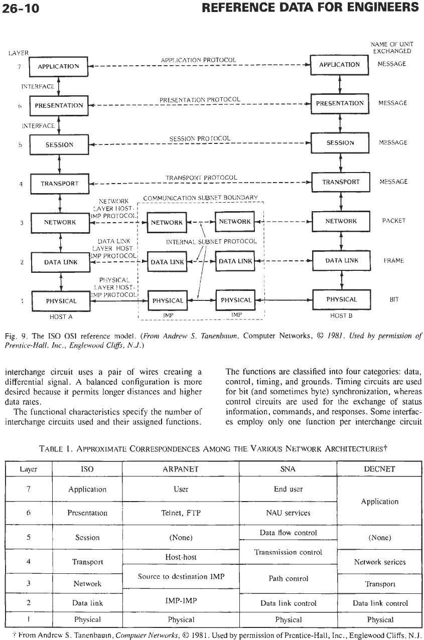
The seven layers
of
the
IS0
OS1 reference model
(Fig.
9)
are: (1) the physical layer,
(2)
the data link
layer,
(3)
the network layer,
(4)
the transport layer,
(5)
the session layer,
(6)
the presentation layer, and
(7)
the
application layer. Specific protocols and their descrip-
tion are considered in subsequent sections.
While the
IS0
reference model is used here as a
guide to describe network functions and protocols, it is
to
be noted that there are a few existing network
architectures,
either designed
for
experimental net-
works, such as the ARPANET, or supplied by computer
*
The International Organization
for
Standardization
(ISO)
is a voluntary nontreaty
group,
the membership
of
which
includes the principal standardization body
of
each represent-
ed nation. The
US
member body is the American National
Standards Institute (ANSI). ANSI
is
a nonprofit, nongovern-
mental organization. It serves as the national clearing house
and coordinating activity
for
voluntary standards in the
US.
manufacturers, such as the Digital Equipment Corpora-
tion DECNET and the IBM Systems Network Architec-
ture (SNA). These architectures are layered but do not
correspond exactly to the
IS0
reference model. See
Table 1. For more information on these architectures,
the reader is referred to references
2
and
3.
THE PHYSICAL LAYER
The physical layer is concerned first of all with the
transparent transmission of a bit stream (regardless of its
meaning) across physical communication resources. In
local networks, the physical medium may be a twisted
pair, a coaxial cable. an optical fiber, or radio, and it
may be privately owned. For long-haul links, the
medium may be either copper wires or optical fibers as
in terrestrial links, or radio as in satellite links; it is
supplied by a common carrier. The methods used for
the transmission of bits across the physical medium
depend on the type of medium used. The description of
these techniques is out of the scope of this chapter, but
suffice it to mention here that bit transmission is done
either in analog form by means of
modems
or in digital
form by means of
line drivers,
and it involves determin-
ing such attributes as data encoding, timing, voltage
levels, data rates, type of operation (half-duplex or
full-duplex, synchronous or asynchronous), etc.
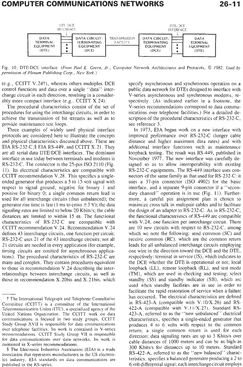
The second concern of the physical layer is to provide
a physical interface between the end-user machine-
which may be a terminal, a computer, or any other
data-processing box, and which is referred to by the
telecommunications administrations as the
Dutu Termi-
nal
Equipment
(DTE)-and the termination point of
the communications circuit-that
is
the modem, line
driver, etc., referred to as the
Data Circuit-Terminating
Equipment
(DCE). (See Fig.
10.)
The definition
of
such an interface requires the determination of four
important characteristics: the mechanical. electrical,
functional, and procedural characteristics.
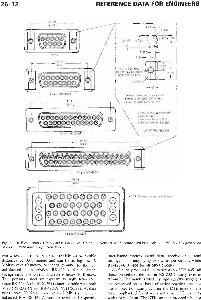
The mechanical aspects pertain to the point of
demarcation, which most typically consists of a plugga-
ble connector. They include specifications of the con-
nector, its latching and mounting arrangements, its
location with respect to the DCE, etc. Fig.
11
illustrates
the various connectors known, along with their
IS0
identification numbers. The number of pins per connec-
tor ranges from
9
to
37.
The electrical aspects pertain to the electrical charac-
teristics
of
the generators and receivers. They specif>>
such parameters as the range of the signal voltage level,
rise-time characteristics of the generator, data signaling
rates as a function of the interconnecting cable distanc-
es, generator and receiver impedances, etc. They also
include specifications regarding the reference with re-
spect to which signal levels are measured; two cases
exist: the “unbalanced” case where
a
single common
return lead is used (or perhaps one common return for
each direction), and the “balanced” case where each
26-10
Layer
7
6
5
4
REFERENCE
DATA
FOR ENGINEERS
IS0
ARPANET SNA DECNET
Application User
End
user
Presentation Telnet, FTP NAU services
Application
Data flow control
Transmission control
Session
(None)
~
(None)
Host-host
Transport Network serices
NAME
OF
UNll
Source to destination IMP
3
t
Transport
Path control
MESSAGE
MESSAGE
MESSAGE
MESSAGE
PACKET
FRAME
BIT
2
Data link
Fig.
9.
The
IS0
OS1
reference model.
(From Andrew
S.
Tunenbuum,
Computer Networks,
0
1981.
Used
by permission
of
Prentice-Hull, Inc., Englewood
Cliffs,
N.J.)
I
Data link control Data link control
IMP-IMP
interchange circuit uses a pair
of
wires creating a
differential signal. A balanced configuration is more
desired because it permits longer distances and higher
data rates.
The functional characteristics specify the number of
interchange circuits used and their assigned functions.
The functions are classified into four categories: data,
control, timing, and grounds. Timing circuits are used
for bit (and sometimes byte) synchronization, whereas
control circuits
are
used for the exchange of status
information, commands, and responses. Some interfac-
es employ only one function per interchange circuit
1
Physical Physical Physical Physical
26-1
1
DATA
TERMINAL
EQUIPMENT
(DTE)
DATA
CIRCUIT-
TRANSMISSION
DATA
TERMINAL
-
TERMINATING
FACILITY
TERMINATING
-
:
EQUIPMENT EQUIPMENT
:
EQUIPMENT
m
(DCE) (DCE)
.
(DE)
-
-
Fig.
10.
DTEiDCE interface.
(From
Paul
E.
Green, Jr.,
Computer Network Architectures and Protocols,
0
1982.
Used
by
permission
of
Plenum Publishing
Corp.,
New
York.
j
(e.g., CCITT V.24t), whereas others multiplex DCE
control functions and data over a single “data” inter-
change circuit in each direction, resulting in a consider-
ably more compact interface (e.g., CCITT X.24).
The procedural characteristics consist of the set of
procedures for using the interchange circuits, in order to
achieve the transmission of bit streams as well as to
provide maintenance test loops.
Three examples
of
widely used physical interface
protocols are considered here to illustrate the concepts
and physical characteristics discussed above. These are
EIA RS-232-C,$ EIA RS-449, and CCITT X.21. They
are all serial data DTEiDCE interfaces. The dominant
interface in use today between terminals and modems is
RS-232-C. The connector is the 25-pin
IS0
21 10 (Fig.
11). Its electrical characteristics are compatible with
CCITT recommendation V.28. This specifies a single-
ended generator that produces a 5 to 15 volt signal with
respect to signal ground, negative for binary 1 and
positive for binary
0;
a single common return lead is
used for all interchange circuits (thus unbalanced); the
generator rise time is fast
(1
ms to cross 13 V); the data
signaling rates are limited to below 20 Kbitsis; the cable
distances are limited to within 15 m. The functional
characteristics
of
RS-232-C are compatible with
CCITT recommendation V.24. Recommendation V.24
defines 43 interchange circuits, one function per circuit;
RS-232-C uses 21
of
the 43 interchange circuits; not all
21 circuits are needed in every application (for example.
timing circuits are omitted for asynchronous applica-
tions). The procedural characteristics of RS-232-C are
many and complex. They contain procedures equivalent
to those in recommendation V.24 describing the inter-
relationships between interchange circuits, as well as
those in recommendation X.20bis and X.2lbis. which
t
The International Telegraph
and
Telephone Consultative
Committee (CCITT) is a committee
of
the International
Telecommunication Union (ITU),
a
specialized agency
of
the
United Nations Organization. The CCITT work on data
communications is focused in two study groups. CCITT
Study Group XVII is responsible for data communications
over telephone facilities. Its work
is contained in V-series
recommendations. CCITT Study Group VI1 is responsible
for data communications over data networks. Its work is
contained in X-series recommendations.
8
The Electronic Industries Association
(EIA)
is a trade
association that represents manufacturers in the
US
electron-
ics industry.
EIA
standards
on
data communications are
published in the RS-series.
specify asynchronous and synchronous operation on a
public data network for DTEs designed to interface with
V-series asynchronous and synchronous modems, re-
spectively. (As indicated earlier in a footnote, the
V-series recommendations correspond to data commu-
nications over telephone facilities
.)
For
a detailed de-
scription of the procedural characteristics of RS-232-C,
see reference 3.
In 1973, EIA began work on a new interface with
improved performance over RS-232-C (longer cable
distance and higher maximum data rates) and with
additional interface functions such as maintenance
loopback testing. The result was RS-449, published in
November 1977. The new interface was carefully de-
signed
so
as to allow interoperability with existing
RS-232-C equipments. The RS-449 interface uses con-
nectors of the same family as that used for RS-232-C: it
uses a 37-pin connector
(IS0
4902) for the basic
interface, and a separate 9-pin connector if a “secon-
dary channel” operation is in use (Fig. 11). Further-
more, a careful pin assignment plan is chosen to
minimize cross talk in multipair cables and to facilitate
the design of an adapter to RS-232-C. As in RS-232-C,
the functional characteristics of RS-449 are compatible
with V.24, one function per interchange circuit. There
are 10 new circuits with respect to RS-232-C, among
which we note the following: send common (SC) and
receive common (RC), which are the common return
leads for all unbalanced interchange circuits employing
one wire in the direction toward the DCE and the DTE,
respectively; terminal in service (IS), which indicates to
the DCE whether the DTE
is
operational or not; local
loopback
(LL),
remote loopback (RL), and test mode
(TM), which are used in checking and testing; select
standby
(SS)
and standby indicator
(SB),
which are
used when standby facilities are in use in order to
facilitate the rapid restoration of service when a failure
has occurred. The electrical characteristics are defined
in RS-423-A (compatible with V.lOiX.26) and
RS-
422-A
(compatible
with
V.
1
liX.27). Standard
RS-
423-A, referred to as the “new unbalanced” electrical
characteristics, specifies a single-ended generator that
produces 4 to 6 volts with respect to the common
return; a single common return is used for each
direction; data signaling rates are up to 3 Kbitsis over
cable distances of 1000 meters and can be as high as
300
Kbitsis for distances up to
10
meters. Standird
RS-422-A, referred to as the “new balanced” charac-
teristics, specifies a balanced generator producing a 2 to
6 volt differential signal; each interchange circuit employs
26-
12
REFERENCE
DATA
FOR ENGINEERS
,
FOR
DTE
SCRELVJJJ
15758
1
r
I
I
I
'Metric
:hread
per
Internatiana!
I
Standard
IS0
261
IS0
Metric
Screu
Threads
General
Plzi
I5
pin
!SO
4903
47
17
46
91
J
37
ptn
IS0
4902
t
13
08
42
67
1
f/l
b
//
34
pin
!SO
2593
Fig.
11.
DCE
connectors.
(From Paul
E.
Green, Jr.,
Computer Network Architectures
and
Protocols,
0
1982. Used
by permission
of
Plenum Publishing Corp., New York.)
two wires; data rates
are
up to
100
Kbitsis over cable
distances of
1000
meters and can be as high as
10
Mbitsis over
10
meters. Standard
RS-449
uses the new
unbalanced characteristics,
RS-423-A,
for all inter-
change circuits when the data rate is below
20
Kbitsis.
This permits direct interoperability with
RS-232-C
since
RS-423-A
(V.
10iX.26)
is interoperable with both
V.28 (RS-232-C)
and
RS-422-A (V.
1
liX.27).
At
data
rates above
20
Kbits/s and up to
2
Mbitsis, the new
balanced
EIA RS-422-A
must be used on
10
specific
interchange circuits (send data, receive data, send
timing,
.
.
.
)
employing two wires per circuit, while
RS-423-A
is used for all other circuits.
As
for the procedural characteristics of
RS-449,
all
those procedures defined in
RS-232-C
carry over to
RS-449.
The newly added test and standby functions
are conceived
on
the basis of action-reaction and thus
are simple. For example, after the DTE turns on the
local loopback
(LL),
it waits until the DCE responds
with test mode on. The DTE can then proceed with test
26-13
data transmission on the send data circuit, expecting to
receive them back on the receive data circuit. Deactiva-
tion follows
a
similar procedure.
The physical characteristics for a general-purpose
DTEiDCE interface for synchronous digital transmis-
sion on public data networks are defined in CCITT
recommendation
X.21.
The DCEs are linked by means
of real digital circuits, possibly through circuit-switch-
ing equipment. When circuit-switched services are
provided,
X.21
also
specifies the call control
procedures, i.e., the protocols by which to establish
(and later to disconnect)
a
physical connection between
two DTEs. Since the establishment of
a
circuit clearly
requires knowledge of the address of the remote DTE
(or its corresponding DCE) and the understanding
of
the various call progress signals, and since these re-
quirements are supposed to be met only at the network
layer (as discussed below), there is a general consensus
that the call control procedure span the first three layers
with the resulting service being offered by the network
layer to the transport layer. Thus, these issues
are
dealt
with in the network layer. The benefit of such a
viewpoint is that of consistency in the network architec-
ture, whereby the classification of functions is the same
regardless of whether the data network is of the circuit-
switched type or the packet-switched type. Indeed, in
packet networks, the network layer takes care of open-
ing a “connection,” called the
“virtual circuit,”
with
the remote DTE before the flow of packets takes place.
Simplicity and enhanced performance were prime
objectives in the design of
X.21.
It permits interface
operation over distances considerably greater than that
available with
V.28,
and for the synchronous data rates
specified by
X.
1-that is, 600,
2400,4800,
9600, and
48
000
bitsis. Accordingly, the new balanced electrical
characteristics (Recommendation
X.27,
introduced
above as EIA
RS-422-A)
are specified for the DCE side
of the interface.
To
allow flexibility in DTE design at
the data rates 600,
2400, 4800,
and 9600 bitsis, the
DTE is permitted to use either the new balanced or the
new unbalanced
(X.26
or
RS-423-A)
electrical charac-
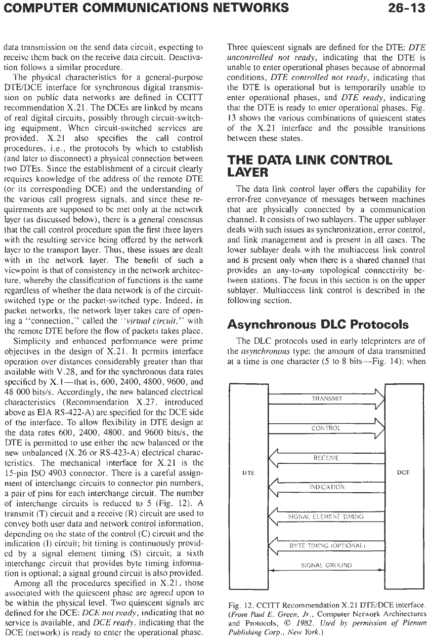
teristics. The mechanical interface for
X.21
is the
15-pin IS0 4903 connector. There is a careful assign-
ment of interchange circuits to connector pin numbers,
a
pair of pins for each interchange circuit. The number
of interchange circuits is reduced to 5 (Fig.
12).
A
transmit
(T)
circuit and a receive
(R)
circuit are used
to
convey both user data and network control information,
depending on the state
of
the control (C) circuit and the
indication
(I)
circuit; bit timing is continuously provid-
ed by a signal element timing
(S)
circuit;
a
sixth
interchange circuit that provides byte timing informa-
tion is optional; a signal ground circuit is also provided.
Among all the procedures specified in
X.21,
those
associated with the quiescent phase are agreed upon to
be within the physical level. Two quiescent signals are
defined for the DCE:
DCE
not
ready,
indicating that no
service is available, and
DCE
ready,
indicating that the
DCE (network) is ready to enter the operational phase.
Three quiescent signals
are
defined for the
DTE:
DTE
uncontrolled
not
ready,
indicating that the DTE is
unable to enter operational phases because of abnormal
conditions,
DTE
controlled
not
ready,
indicating that
the DTE is operational but is temporarily unable to
enter operational phases, and
DTE
ready,
indicating
that the DTE is ready to enter operational phases. Fig.
13
shows the various combinations of quiescent states
of
the
X.21
interface and the possible transitions
between these states.
THE
DATA
LINK CONTROL
LAYER
The data link control layer offers the capability for
error-free conveyance of messages between machines
that are physically connected by
a
communication
channel. It consists of two sublayers. The upper sublayer
deals with such issues as synchronization, error control,
and link management and is present in all cases. The
lower sublayer deals with the multiaccess link control
and is present only when there is
a
shared channel that
provides an any-to-any topological connectivity be-
tween stations. The focus in this section is on the upper
sublayer. Multiaccess link control is described in the
following section.
Asynchronous DLC Protocols
The DLC protocols used in early teleprinters are
of
the
asynchronous
type: the amount of data transmitted
at
a
time is one character (5 to
8
bits-Fig.
14);
when
DTE
DCE
BYTE
TIMING (OPTIONAL1
-
SIGNAL.
GROUND
Fig.
12.
CCITT Recommendation
X.21
DTEiDCE interface.
(From Paul
E.
Green,
Jr.,
Computer
Network
Architectures
and
Protocols,
0
1982.
Used by permission
of
Plenum
Publishing
Corp., New
York.)

26-14
REFERENCE
DATA
FOR
ENGINEERS
READY
(DTE READY, DCE READY)
0
OFF
DTE READY,
DCE NOT READY
0
OFF
LEGEND Each state
is
represented
by
an
ellipse
Lherein
!he stale
name
and
number
are iidicateo. together
with
the
signais
on
the
four
intercnanye
circufts u,hich represent
that
state
Each
state
transition
15
represented
hb
an
arrow
and the
equipment
responsible for the transition
!DTE
or
DCEI
15
.nd:cated beside
thar
arrow
DCE RESPONSIBLE FOR
-1
DTE THE TRANSlTlOh
11
=State
number
t
=Signal
an
T
circuit
c
=
S,ynal
on
c
ClKUlt
r
=
Sqnal
on
R circuit
I
~Siynai
on
I
circuit
T
=
Transmit
interchange c.rcut
C
=
Control
lnterchanye
crrculi
R
=
Receire interchange circuit
I
=
Indicat.on interchange circuit
STATE NAME
4
DTE
0
and
1
01
OFF
and
ON
Refers
io
steady binary conditions
Refers
:o
alternate
binary
0
and
binary
1
conditions
Reipectivel~. refer
to
contmuous
OFF
!bmary
li
and
ON
lbliary
0)
iondltlons
Fig.
13.
CCITT Recommendation
X.21
quiescent states.
(From Paul
E.
Green, Jr.,
Computer Network Architectures and
Protocols,
0
1982.
Used
by
permission
of
Plenum Publishing
Corp.,
New York.)
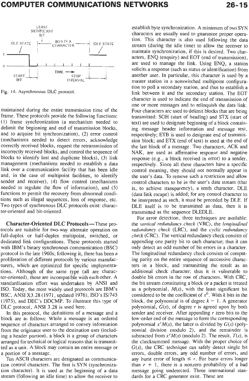
no transmission is taking place, the channel is in the idle
state, which is represented by a continuous
1.
When a
character is to be transmitted, the terminal transmits a
0
(the start bit) followed by the character (of fixed length),
and then followed by a
1
(the idle state) for a minimum
period
of
time called the stop interval. The receiver
The start-stop protocols are simple but present sever-
a1 disadvantages, among others the overhead of a start
bit and a stop interval associated with each character,
and the lack of any inherent link control capability.
Synchronous
DLC
Protocols
determines the initial sampling from the
1
to
0
transi-
tion, using a clock sixteen times the transmission rate.
The sampling period is known from the bit transmission
rate. Bit synchronism
is
maintained only during the
transmission time of a character. Anytime following the
stop interval, another character can be transmitted.
To
improve the efficiency
of
a data link and provide
link control capability,
synchronous
protocols were
introduced.
A
block of several characters referred
to
as
a
frame
is transmitted as a whole, with bit synchronism
LEAS1
SIGNIFICANT
B/T
1
BITS IN A
IDLESTATE
1
-
CHARACTER1
IDLY
I
Fig.
14.
Asynchronous
DLC
protocol.
maintained during the entire transmission time of the
frame. These protocols provide the following functions:
(1)
frame synchronization (a mechanism needed to
delimit the beginning and end of transmission blocks,
and to acquire bit synchronization),
(2)
error control
(mechanisms needed to detect errors, acknowledge
correctly received blocks, request the retransmission of
incorrectly received blocks, and control the sequence of
blocks to identify lost and duplicate blocks),
(3)
link
management (mechanisms needed to establish a data
link over a communication facility that has been idle
and, in the case of multipoint facilities, to identify
sender and receiver),
(4)
flow control (mechanisms
needed to regulate the flow of information), and
(5)
functions to permit the recovery from abnormal condi-
tions such as illegal sequences, loss of response, etc.
Two types of synchronous DLC protocols exist: charac-
ter-oriented and bit-oriented.
Character-Oriented DLC Protocols-These pro-
tocols are suitable for two-way alternate operation on
full-duplex or half-duplex multipoint, switched, or
dedicated link configurations. These protocols started
with IBM’s binary synchronous communication (BSC)
protocol in the late 1960s; following it, there has been a
proliferation of different protocols by various manufac-
turers, which are optimized for specific implementa-
tions. Although of the same type (all are charac-
ter-oriented)
,
these are incompatible with each other. A
standardization effort was undertaken by ANSI and
KO. Today, the most widely used protocols are IBM’s
BSC, ANSI X3.28 (1971, updated
1976),
KO’s 19745
(1975), and DEC’s DDCMP. To illustrate this type of
DLC protocol, ANSI 3.28 is used here.
In this protocol, the definitions of
a
message and a
block are as follows: While a message is an ordered
sequence of characters arranged to convey information
from the originator user to the destination user (includ-
ing a header portion), a block is a group of characters
arranged for technical or logical reasons that is transmit-
ted as a unit.
A
block may contain an entire message or
a portion of a message.
Ten ASCII characters are designated as communica-
tion control characters. The first is SYN (synchroniza-
tion character). It is used at the beginning of a data
stream (following an idle time) to allow the receiver to
establish byte synchronization. A minimum of two SYN
characters are usually used to guarantee proper opera-
tion. This character is also used following the data
stream (during the idle time) to allow the receiver to
maintain synchronization, if this is desired. Two char-
acters, ENQ (enquiry) and EOT (end of transmission),
are used to manage the link. Using ENQ, a station
solicits a response (such
as
status or identification) from
another user. In particular, this character is used by a
master station in a nonswitched multipoint configura-
tion to poll a secondary station, and thus to establish a
link between it and the secondary station. The EOT
character is used to indicate the end of transmission of
one or more messages and to relinquish the data link.
Four characters are used to delimit blocks that are being
transmitted:
SOH
(start of heading) and STX (start of
text) are used
to
designate beginning of a block contain-
ing message header information and message text,
respectively; ETB is used
to
designate end of transmis-
sion block; and ETX (end of text) is used at the end of
the last block of a message. Two characters, ACK and
NAK, are used as affirmative response and negative
response (e.g., a block received in error) to a sender,
respectively. Since all these characters have a specific
control meaning, they should not normally appear in
the user’s data. To remove such a restriction and allow
control characters to be in the user’s data stream (that
is, to achieve transparency), a tenth character, DLE
(data link escape) is added; for any control character to
be interpreted as such, it must be preceded by DLE. If
DLE itself is to be transmitted as data, then it is
transmitted as the sequence DLEDLE.
For error detection, three techniques are available:
the
vertical redundancy check
(VRC), the
longitudinal
redundancy check
(LRC), and the
cyclic redundancy
check
(CRC). The vertical redundancy check consists of
appending one parity bit to each character; thus it can
only detect an odd number of bit errors in a character.
The longitudinal redundancy check consists of comput-
ing parity on the entire sequence of successive charac-
ters in a block, and transmitting the result as an
additional check character; thus it is vulnerable to
double bit errors in the row of characters. With CRC,
the bit stream constituting a block or a packet is treated
as a polynomial,
M(x),
with the least significant bit
considered to be the coefficient of
xo.
With
k
bits in the
block, the polynomial is of degree
k
-
1.
A generator
polynomial,
G(x),
of degree
r
is agreed upon by both
sender and receiver. After appending
r
zero bits to the
low-order end
of
the message to
form
the corresponding
polynomial
x‘M(x),
the latter is divided by
G(x)
(poly-
nomial division modulo
2),
and the remainder is
subtracted fromxTM(x) (modulo
2).
The result,
T(x),
is
the checksummed message. With the proper choice of
G(x),
the CRC technique can safely detect single bit
errors, double errors, any odd number of errors, and
any burst error
of
length
5
r.
For burst errors longer
than
r
+
1,
there is a nonzero probability of a bad
message going undetected. Three international stan-
dards for a CRC generator exist. These are