Munson B.R. Fundamentals of Fluid Mechanics
Подождите немного. Документ загружается.

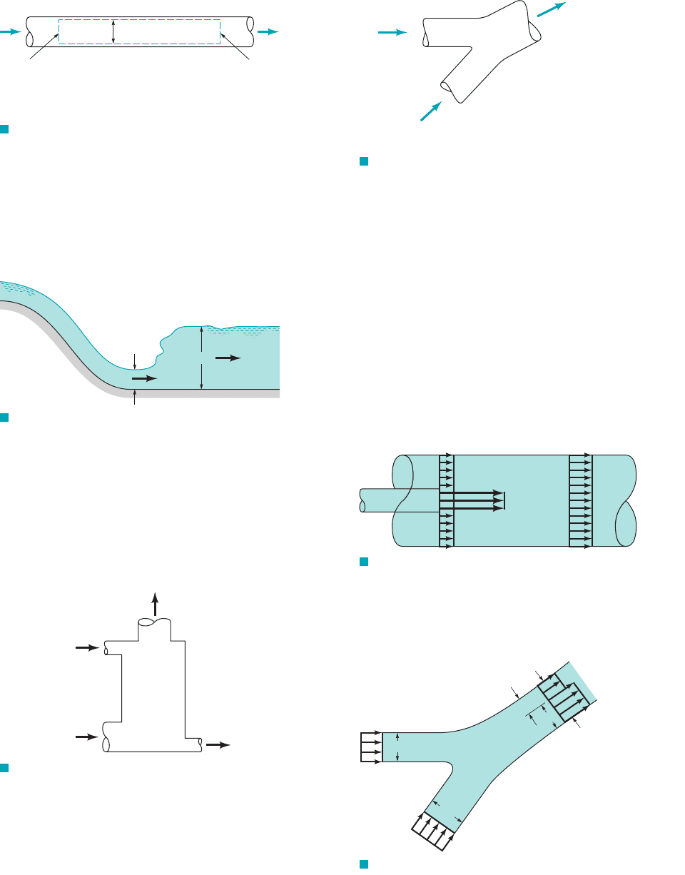
5.11 Air flows steadily between two cross sections in a long,
straight section of 0.1-m inside diameter pipe. The static tempera-
ture and pressure at each section are indicated in Fig. P5.11. If the
average air velocity at section 112is 205 m兾s, determine the average
air velocity at section 122.
Problems
247
F I G U R E P5.11
D = 0.1 m
Section (1) Section (2)
p
1
= 77 kPa (abs)
T
1
= 268 K
V
1
= 205 m/s
p
2
= 45 kPa (abs)
T
2
= 240 K
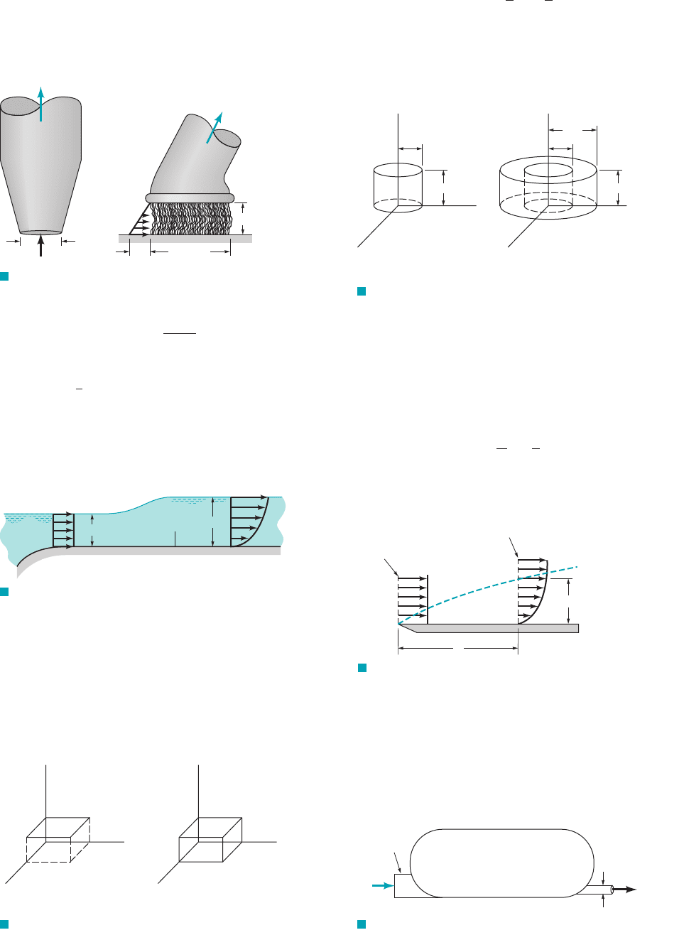
5.12 A hydraulic jump (see Video V10.10) is in place downstream
from a spillway as indicated in Fig. P5.12. Upstream of the jump,
the depth of the stream is 0.6 ft and the average stream velocity is
18 ft兾s. Just downstream of the jump, the average stream velocity is
3.4 ft兾s. Calculate the depth of the stream, h, just downstream of
the jump.
F I G U R E P5.12
18 ft/s
3.4 ft/s
0.6 ft
h
F I G U R E P5.13
Wet air
m
•
= 156,900 lbm/hr
Warm water
m
•
= 250,000 lbm/hr
Dry air
m
•
= 151,000 lbm/hr
Cooled
water
F I G U R E P5.15
Water and
alcohol mix
Water
Q = 0.1 m
3
/s
Alcohol (
SG = 0.8)
Q = 0.3 m
3
/s
5.13 An evaporative cooling tower (see Fig. P5.13) is used to cool
water from 110 to . Water enters the tower at a rate of
. Dry air (no water vapor) flows into the tower at a
rate of . If the rate of wet air flow out of the tower
is , determine the rate of water evaporation in
and the rate of cooled water flow in .lbm
Ⲑ
hrlbm
Ⲑ
hr
156,900 lbm
Ⲑ
hr
151,000 lbm
Ⲑ
hr
250,000 lbm
Ⲑ
hr
80°F
5.14 At cruise conditions, air flows into a jet engine at a steady
rate of 65 lbm兾s. Fuel enters the engine at a steady rate of 0.60 lbm兾s.
The average velocity of the exhaust gases is 1500 ft兾s relative to the
engine. If the engine exhaust effective cross-sectional area is
estimate the density of the exhaust gases in lbm
Ⲑ
ft
3
.3.5 ft
2
,
5.15 Water at 0.1 m
3
/s and alcohol (SG⫽0.8) at 0.3 m
3
/s are mixed
in a y-duct as shown in Fig. 5.15. What is the average density of the
mixture of alcohol and water?
5.16 Freshwater flows steadily into an open 55-gal drum initially
filled with seawater. The freshwater mixes thoroughly with the sea-
water and the mixture overflows out of the drum. If the freshwater
flowrate is 10 gal/min, estimate the time in seconds required to de-
crease the difference between the density of the mixture and the
density of freshwater by 50%.
Section 5.1.2 Fixed, Nondeforming Control Volume—
Nonuniform Velocity Profile
5.17 A water jet pump 1see Fig. P5.172involves a jet cross-sectional
area of and a jet velocity of 30 m兾s. The jet is surrounded by
entrained water. The total cross-sectional area associated with the
jet and entrained streams is These two fluid streams leave
the pump thoroughly mixed with an average velocity of 6 m兾s
through a cross-sectional area of Determine the pumping
rate 1i.e., the entrained fluid flowrate2involved in liters兾s.
0.075 m
2
.
0.075 m
2
.
0.01 m
2
,
F I G U R E P5.17
Entrained
water
Entrained
water
30 m/s
jet
6 m/s
5.18 Two rivers merge to form a larger river as shown in
Fig. P5.18. At a location downstream from the junction 1before the
two streams completely merge2, the nonuniform velocity profile is
as shown and the depth is 6 ft. Determine the value of V.
F I G U R E P5.18
4 ft/s
3 ft/s
Depth = 3 ft
Depth = 5 ft
80 ft
50 ft
0.8 V
V
70 ft
30 ft
JWCL068_ch05_187-262.qxd 9/23/08 10:19 AM Page 247
5.19 Various types of attachments can be used with the shop vac
shown in Video V5.2. Two such attachments are shown in Fig. P5.19
—a nozzle and a brush. The flowrate is (a) Determine the
average velocity through the nozzle entrance, (b) Assume the air
enters the brush attachment in a radial direction all around the brush
with a velocity profile that varies linearly from 0 to along the length
of the bristles as shown in the figure. Determine the value of V
b
.
V
b
V
n
.
1 ft
3
/s.
248 Chapter 5 ■ Finite Control Volume Analysis
F I G U R E P5.19
Q = 1 ft
3
/s
Q = 1 ft
3
/s
V
n
2-in. dia.
1.5 in.
3-in. dia.
V
b
F I G U R E P5.23
z
(a)
1 m
1 m
z
(b)
1 m
2 m
1 m
5.20 An appropriate turbulent pipe flow velocity profile is
where centerline velocity, local radius, pipe radius,
and vector along pipe centerline. Determine the ratio of av-
erage velocity, to centerline velocity, for (a) (b)
(c) (d) Compare the different velocity profiles.
5.21 As shown in Fig. P5.21, at the entrance to a 3-ft-wide channel
the velocity distribution is uniform with a velocity V. Further down-
stream the velocity profile is given by where u is in
ft兾s and y is in ft. Determine the value of V.
u 4y 2y
2
,
n 10.n 8,
n 6,n 4,u
c
,u,
i
ˆ
unit
R r u
c
V u
c
a
R r
R
b
1
n
i
ˆ
F I G U R E P5.22
y
x
z
2
5
5
y
x
z
2
5
5
(
a)(b)
5.23 An incompressible flow velocity field (water) is given as
where r is in meters. (a) Calculate the mass flowrate through the
cylindrical surface at m from to m as shown in
Fig.P5.23a. (b) Show that mass is conserved in the annular control
volume from m to m and to m as shown
in Fig. P5.23b.
z 1z 0r 2r 1
z 1z 0r 1
V
1
r
e
r
ˆ
1
r
e
u
ˆ
m
s
5.24 Flow of a viscous fluid over a flat plate surface results in the
development of a region of reduced velocity adjacent to the wetted
surface as depicted in Fig. P5.24. This region of reduced flow is
called a boundary layer. At the leading edge of the plate, the veloc-
ity profile may be considered uniformly distributed with a value U.
All along the outer edge of the boundary layer, the fluid velocity
component parallel to the plate surface is also U. If the x direction
velocity profile at section 122is
develop an expression for the volume flowrate through the edge of
the boundary layer from the leading edge to a location downstream
at x where the boundary layer thickness is d.
u
U
a
y
d
b
1
7
F I G U R E P5.24
U
U
x
δ
Section (1)
Section (2)
Outer edge
of
boundary
layer
F I G U R E P5.25
Tank volume = 20 ft
3
1.2 in.
700 ft/s
0.0035 slugs/ft
3
10 ft
3
/s
Compressor
0.00238 slugs/ft
3
Section 5.1.2 Fixed, Nondeforming Control Volume—
Unsteady Flow
5.25 Air at standard conditions enters the compressor shown in Fig.
P5.25 at a rate of It leaves the tank through a 1.2-in.-diame-
ter pipe with a density of and a uniform speed of
. (a) Determine the rate 1slugs s2at which the mass of air in
the tank is increasing or decreasing. (b) Determine the average time
rate of change of air density within the tank.
700 ft
s
slugs
ft
3
0.0035
10 ft
3
s.
F I G U R E P5.21
u = 4y – 2y
2
x
1 ft
0.75 ft
y
V
5.22 A water flow situation is described by the velocity field equation
where x, y, and z are in feet. (a) Determine the mass flowrate through
the rectangular area in the plane corresponding to feet having
corners at (x,y, z) (0, 0, 2), (5, 0, 2), (5, 5, 2), and (0, 5, 2) as shown
in Fig P5.22a. (b) Show that mass is conserved in the control volume
having corners at (x,y,z) (0, 0, 2), (5, 0, 2), (5, 5,2), (0, 5,2), (0, 0, 0),
(5, 0, 0), (5, 5, 0), and (0, 5, 0), as shown in Fig. P5.22b.
z 2
V 13x 22 i
ˆ
12y 42 j
ˆ
5zk
ˆ
ft
s
JWCL068_ch05_187-262.qxd 9/23/08 10:20 AM Page 248
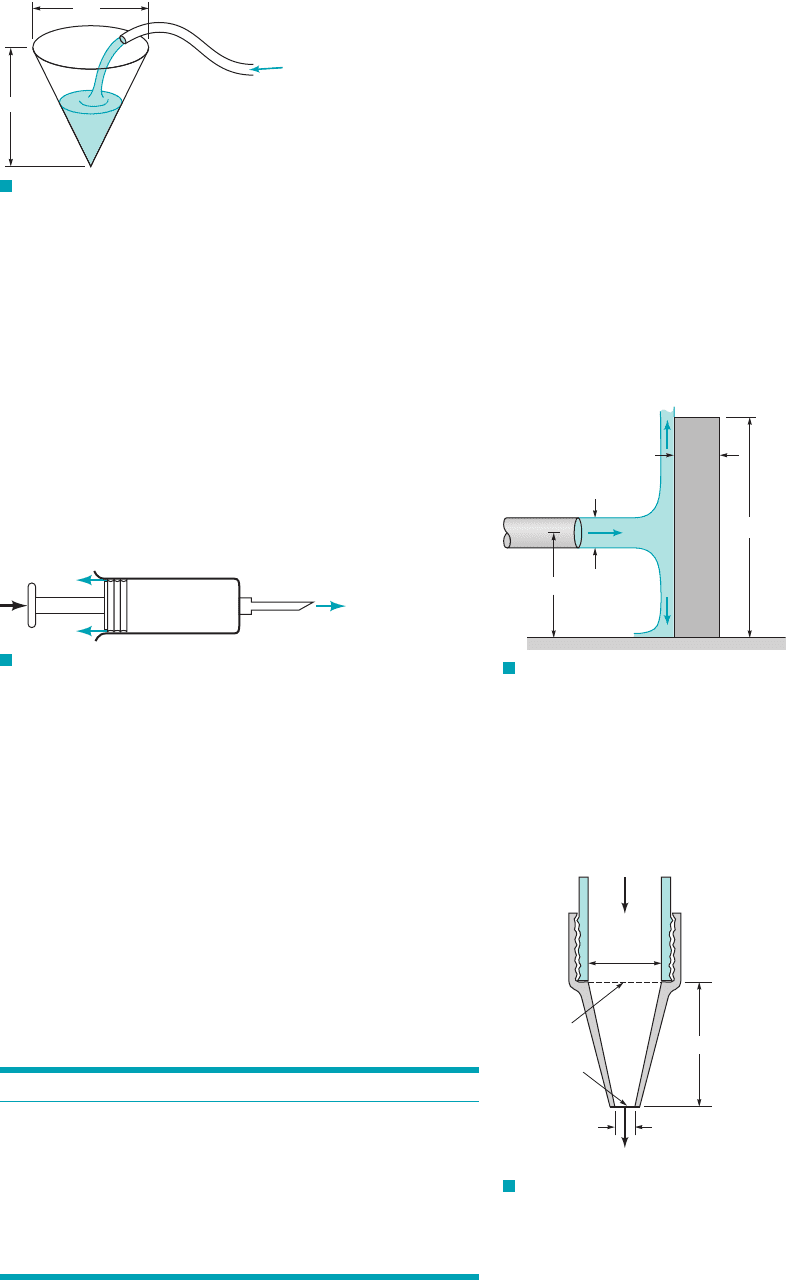
5.26 Estimate the time required to fill with water a cone-shaped
container (see Fig. P5.26) 5 ft high and 5 ft across at the top if the
filling rate is .20 gal
min
Problems
249
F I G U R E P5.26
5 ft
5 ft
†5.27 Estimate the maximum flowrate of rainwater 1during a heavy
rain2that you would expect from the downspout connected to the gut-
ters of your house. List all assumptions and show all calculations.
Section 5.1.3 Moving, Nondeforming Control Volume
5.28 For an automobile moving along a highway, describe the con-
trol volume you would use to estimate the flowrate of air across the
radiator. Explain how you would estimate the velocity of that air.
Section 5.1.4 Deforming Control Volume
5.29 A hypodermic syringe (see Fig. P5.29) is used to apply a vac-
cine. If the plunger is moved forward at the steady rate of 20 mm/s
and if vaccine leaks past the plunger at 0.1 of the volume flowrate out
the needle opening, calculate the average velocity of the needle exit
flow. The inside diameters of the syringe and the needle are 20 mm
and 0.7 mm.
F I G U R E P5.29
Q
leak
Q
out
5.30 The Hoover Dam (see Video V2.4) backs up the Colorado
River and creates Lake Mead, which is approximately 115 miles long
and has a surface area of approximately 225 square miles. If during
flood conditions the Colorado River flows into the lake at a rate of
45,000 cfs and the outflow from the dam is 8000 cfs, how many feet
per 24-hour day will the lake level rise?
5.31 Storm sewerbackupcauses your basement toflood at the steady
rate of 1 in. of depth per hour. The basement floor area is
What capacity 1gal兾min2pump would you rent to (a) keep the water
accumulated in your basement at a constant leveluntil the storm sewer
is blocked off, and (b) reduce the water accumulation in your base-
ment at a rate of 3 in.兾hr even while the backup problem exists?
5.32 (See Fluids in the News article “New 1.6 gpf standards,”
Section 5.1.2.) When a toilet is flushed, the water depth, h, in the
tank as a function of time, t, is as given in the table. The size of the
rectangular tank is 19 in. by 7.5 in. (a) Determine the volume of
water used per flush, gpf. (b) Plot the flowrate for .0 t 6 s
1500 ft
2
.
t (s) h (in.)
0 5.70
0.5 5.33
1.0 4.80
2.0 3.45
3.0 2.40
4.0 1.50
5.0 0.75
6.0 0
Section 5.2.1 Derivation of the Linear Momentum
Equation
5.33 What is fluid linear momentum and the “flow” of linear
momentum?
5.34 Explain the physical meaning of each of the terms of the lin-
ear momentum equation (Eq. 5.22).
5.35 What is an inertial control volume?
5.36 Distinguish between body and surface forces.
5.37 Obtain a photograph/image of a situation in which the linear
momentum of a fluid changes during flow from one location to an-
other. Explain briefly how force is involved.
Section 5.2.2 Application of the Linear Momentum
Equation (Also see Lab Problems 5.140, 5.141, 5.142,
and 5.143.)
5.38 A 10-mm diameter jet of water is deflected by a homoge-
neous rectangular block (15 mm by 200 mm by 100 mm) that
weighs 6 N as shown in Video V5.6 and Fig. P5.38. Determine the
minimum volume flowrate needed to tip the block.
F I G U R E P5.38
0.050 m
0.010 m
0.10 m
0.015 m
Q
5.39 Determine the anchoring force required to hold in place the
conical nozzle attached to the end of the laboratory sink faucet
shown in Fig. P5.39 when the water flowrate is 10 gal/min. The
nozzle weight is 0.2 lb. The nozzle inlet and exit inside diameters
are 0.6 and 0.2 in., respectively. The nozzle axis is vertical and the
axial distance between sections (1) and (2) is 1.2 in. The pressure at
section (1) is 68 psi.
F I G U R E P5.39
D
1
=
0.6 in.
Q
= 10 gal/min
1.2 in.
Section (2)
Section (1)
D
2
= 0.2 in.
5.40 Water flows through a horizontal, pipe bend as is illus-
trated in Fig. P5.40. The flow cross section area is constant at a value
of . The flow velocity everywhere in the bend is .15 m
s9000 mm
2
180°
JWCL068_ch05_187-262.qxd 9/23/08 10:20 AM Page 249
The pressures at the entrance and exit of the bend are 210 and 165 kPa,
respectively. Calculate the horizontal (x and y) components of the an-
choring force needed to hold the bend in place.
5.41 Water enters the horizontal, circular cross-sectional, sudden
contraction nozzle sketched in Fig. P5.41 at section 112with a uni-
formly distributed velocity of 25 ft兾s and a pressure of 75 psi. The
water exits from the nozzle into the atmosphere at section 122where
the uniformly distributed velocity is 100 ft兾s. Determine the axial
component of the anchoring force required to hold the contraction
in place.
250 Chapter 5 ■ Finite Control Volume Analysis
F I G U R E P5.40
z
y
x
F I G U R E P5.41
D
1
= 3 in.
p
1
= 75 psi
V
1
= 25 ft/s
p
2
=
0 psi
V
2
=
100 ft/s
Section (2)
Section (1)
F I G U R E P5.44
D = 12 in.
Section (1) Section (2)
p
1
= 690 kPa (abs)
T
1
= 300 K
p
2
= 127 kPa (abs)
T
2
= 252 K
V
2
= 320 m/s
5.42 The four devices shown in Fig. P5.42 rest on frictionless
wheels, are restricted to move in the x direction only, and are ini-
tially held stationary. The pressure at the inlets and outlets of each
is atmospheric, and the flow is incompressible. The contents of
each device is not known. When released, which devices will move
to the right and which to the left? Explain.
F I G U R E P5.42
(a)
(
c)
(
b)
(
d)
5.43 Exhaust (assumed to have the properties of standard air)
leaves the 4-ft-diameter chimney shown in Video V5.4 and
Fig. P5.43 with a speed of Because of the wind, after a few
diameters downstream the exhaust flows in a horizontal direction
with the speed of the wind, Determine the horizontal com-
ponent of the force that the blowing wind puts on the exhaust
gases.
15 ft/s.
6 ft/s.
5.44 Air flows steadily between two cross sections in a long, straight
section of 12-in.-inside diameter pipe. The static temperature and pres-
sure at each section are indicated in Fig P5.44. If the average air
velocity at section (2) is 320 m/s, determine the average air velocity at
section (1). Determine the frictional force exerted by the pipe wall on
the air flowing between sections (1) and (2). Assume uniform velocity
distributions at each section.
F I G U R E P5.43
15 ft/s
15 ft/s
6 ft/s
4 ft
5.45 Determine the magnitude and direction of the anchoring force
needed to hold the horizontal elbow and nozzle combination shown
in Fig. P5.45 in place. Atmospheric pressure is 100 kPa(abs). The
gage pressure at section (1) is 100 kPa. At section (2), the water ex-
its to the atmosphere.
F I G U R E P5.45
160 mm
300 mm
Section (2)
Section (1)
y
x
Water
V
2
V
1
p
1
= 100 kPa
V
1
= 2 m/s
5.46 Water flows as two free jets from the tee attached to the pipe
shown in Fig. P5.46. The exit speed is 15 m兾s. If viscous effects
and gravity are negligible, determine the x and y components of the
force that the pipe exerts on the tee.
F I G U R E P5.46
y
x
V
= 15 m/s
V = 15 m/s
Area = 0.3 m
2
Area = 0.5 m
2
Area = 1 m
2
TeePipe
JWCL068_ch05_187-262.qxd 9/23/08 10:20 AM Page 250
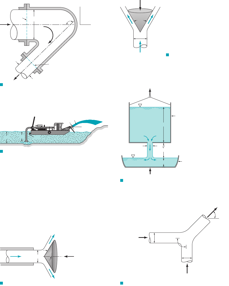
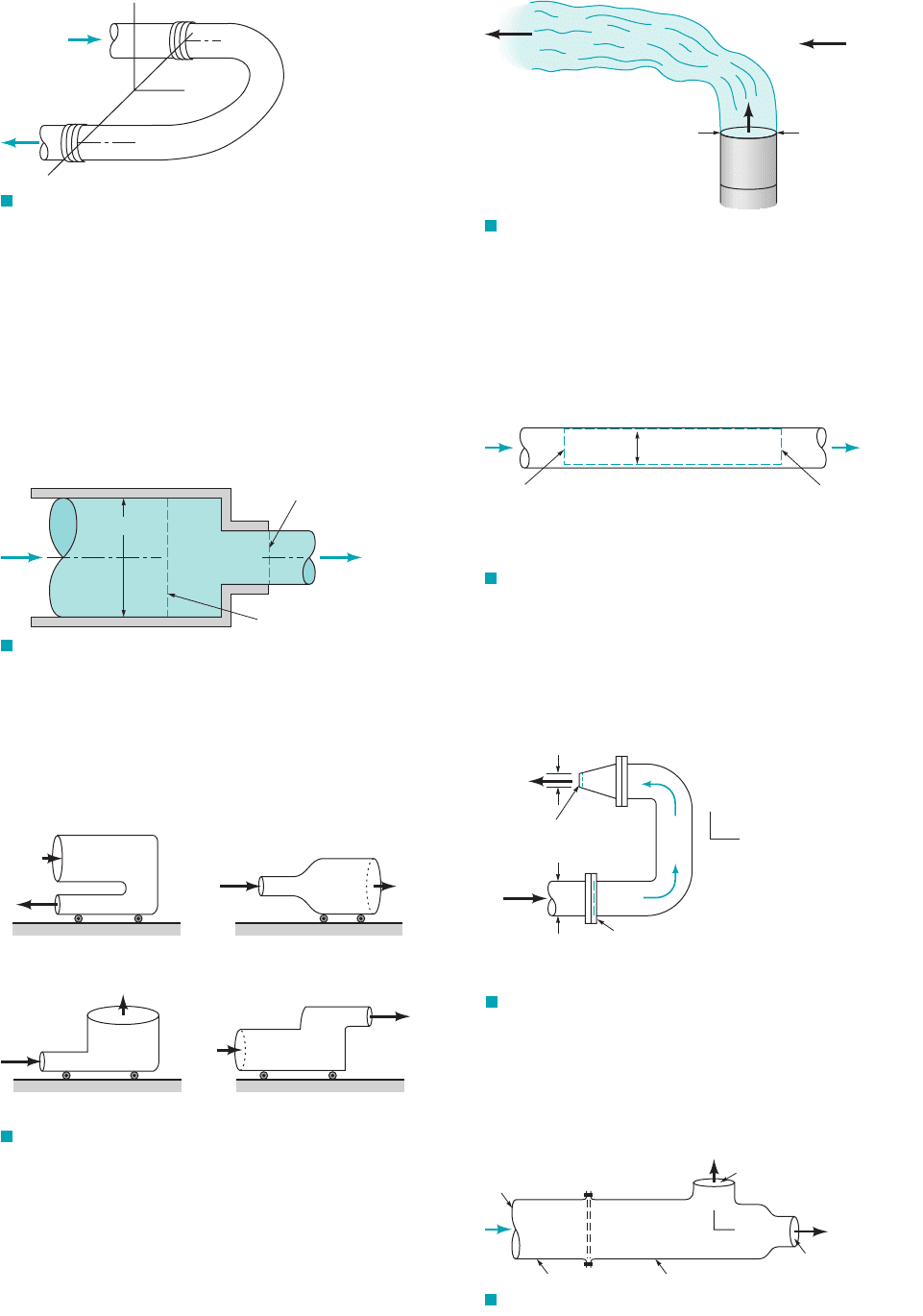
5.47 A converging elbow (see Fig. P5.47) turns water through an
angle of in a vertical plane. The flow cross section diameter is
400 mm at the elbow inlet, section (1), and 200 mm at the elbow out-
let, section (2). The elbow flow passage volume is between
sections (1) and (2). The water volume flowrate is and the
elbow inlet and outlet pressures are 150 kPa and 90 kPa. The elbow
mass is 12 kg. Calculate the horizontal (x direction) and vertical
(z direction) anchoring forces required to hold the elbow in place.
0.4 m
3
Ⲑ
s
0.2 m
3
135°
Problems
251
F I G U R E P5.47
Section
(1)
Section (2)
D
1
= 400 mm
D
2
=
200 mm
135°
x
z
5.48 The hydraulic dredge shown in Fig. P5.48 is used to dredge
sand from a river bottom. Estimate the thrust needed from the pro-
peller to hold the boat stationary. Assume the specific gravity of the
sand兾water mixture is SG ⫽ 1.2.
F I G U R E P5.48
2-ft diameter
30°
30 ft/s
9 ft
7 ft
Prop
5.49 A static thrust stand is to be designed for testing a specific jet
engine. Knowing the following conditions for a typical test,
intake air velocity
exhaust gas velocity
intake cross section area
intake static pressure
intake static temperature
exhaust gas pressure
estimate a nominal thrust to design for.
5.50 A horizontal, circular cross-sectional jet of air having a diam-
eter of 6 in. strikes a conical deflector as shown in Fig. P5.50.
A horizontal anchoring force of 5 lb is required to hold the cone in
⫽ 0 psi
⫽ 480 °R
⫽ 11.4 psia
⫽ 10 ft
2
⫽ 1640 ft
Ⲑ
s
⫽ 700 ft
Ⲑ
s
F I G U R E P5.50
6 in.
60°
F
A
= 5 lb
place. Estimate the nozzle flowrate in . The magnitude of the
velocity of the air remains constant.
5.51 A vertical, circular cross-sectional jet of air strikes a conical de-
flector as indicated in Fig. P5.51. A vertical anchoring force of 0.1 N
is required to hold the deflector in place. Determine the mass 1kg2of
the deflector. The magnitude of velocity of the air remains constant.
ft
3
Ⲑ
s
F I G U R E P5.51
0.1 m
V = 30 m/s
F
A
= 0.1 N
60°
5.52 Water flows from a large tank into a dish as shown in Fig.
P5.52. (a) If at the instant shown the tank and the water in it
weigh what is the tension, in the cable supporting the
tank? (b) If at the instant shown the dish and the water in it weigh
lb, what is the force, needed to support the dish?F
2
,W
2
T
1
,W
1
lb,
F I G U R E P5.53
90°
V
1
=10 ft /s
V
2
= 10 ft /s
V
0.1 ft
0.1 ft
θ
F I G U R E P5.52
0.1-ft diameter
Dish
Tank
10 ft
12 ft
2 ft
F
2
T
1
5.53 Two water jets of equal size and speed strike each other as
shown in Fig. P5.53. Determine the speed, V, and direction, of
the resulting combined jet. Gravity is negligible.
u,
JWCL068_ch05_187-262.qxd 9/23/08 10:20 AM Page 251
5.54 Assuming frictionless, incompressible, one-dimensional flow
of water through the horizontal tee connection sketched in Fig.
P5.54, estimate values of the xand y components of the force exerted
by the tee on the water. Each pipe has an inside diameter of 1 m.
252 Chapter 5 ■ Finite Control Volume Analysis
F I G U R E P5.54
Section (3)
Q
3
=
10 m
3
/s
Section (2)
Section (1)
x
y
z
V
1
= 6 m/s
p
1
= 200 kPa
F I G U R E P5.55
10 ft
4 ft/s
1.5 ft
F I G U R E P5.56
F
z
F
x
F I G U R E P5.57
V
j
=
40 m/s
D
j
= 30 mm
V
3
V
2
30°
90°
F
A
5.55 Determine the magnitude of the horizontal component of the
anchoring force required to hold in place the sluice gate shown in
Fig. 5.55. Compare this result with the size of the horizontal com-
ponent of the anchoring force required to hold in place the sluice
gate when it is closed and the depth of water upstream is 10 ft.
5.56 The rocket shown in Fig. P5.56. is held stationary by the hor-
izontal force, F
x
, and the vertical force, F
z
. The velocity and pres-
sure of the exhaust gas are 5000 ft/s and 20 psia at the nozzle exit,
which has a cross section area of 60 in.
2
. The exhaust mass flowrate
is constant at 21 lbm/s. Determine the value of the restraining force
F
x
. Assume the exhaust flow is essentially horizontal.
5.57 A horizontal circular jet of air strikes a stationary flat plate as
indicated in Fig. 5.57. The jet velocity is 40 m/s and the jet diameter
is 30 mm. If the air velocity magnitude remains constant as the air
flows over the plate surface in the directions shown, determine: (a)
the magnitude of F
A,
the anchoring force required to hold the plate
stationary; (b) the fraction of mass flow along the plate surface in
each of the two directions shown; (c) the magnitude of F
A,
the an-
choring force required to allow the plate to move to the right at a
constant speed of 10 m/s.
5.58 Water is sprayed radially outward over as indicated in
Fig. P5.58. The jet sheet is in the horizontal plane. If the jet veloc-
ity at the nozzle exit is 20 ft兾s, determine the direction and magni-
tude of the resultant horizontal anchoring force required to hold the
nozzle in place.
180°
F I G U R E P5.58
8 in. 0.5 in.
V =
20 ft/s
5.59 A sheet of water of uniform thickness flows
from the device shown in Fig. P5.59. The water enters vertically
through the inlet pipe and exits horizontally with a speed that varies
linearly from 0 to 10 m兾s along the 0.2-m length of the slit. Deter-
mine the y component of anchoring force necessary to hold this de-
vice stationary.
1h ⫽ 0.01 m2
F I G U R E P5.59
0.2 m
h = 0.01 m
x
y
0 m/s
10 m/s
Q
F I G U R E P5.60
Variable mesh screen
Section (2)Section (1)
p
1
= 0.2 psi
V
1
= 100 ft/s
D = 2 ft
p
2
= 0.15 psi
5.60 A variable mesh screen produces a linear and axisymmetric
velocity profile as indicated in Fig. P5.60 in the air flow through a
JWCL068_ch05_187-262.qxd 9/23/08 10:20 AM Page 252
2-ft-diameter circular cross section duct. The static pressures up-
stream and downstream of the screen are 0.2 and 0.15 psi and are
uniformly distributed over the flow cross section area. Neglecting
the force exerted by the duct wall on the flowing air, calculate the
screen drag force.
5.61 Water flows vertically upward in a circular cross-sectional
pipe as shown in Fig. P5.61. At section 112, the velocity profile over
the cross-sectional area is uniform. At section 122, the velocity pro-
file is
where local velocity vector, centerline velocity in the
axial direction, pipe radius, and radius from pipe axis.
Develop an expression for the fluid pressure drop that occurs be-
tween sections 112and 122.
r ⫽R ⫽
w
c
⫽V ⫽
V ⫽ w
c
a
R ⫺ r
R
b
1
Ⲑ
7
k
ˆ
Problems
253
F I G U R E P5.61
Section (1)
Section (2)
R
r
z
5.62 In a laminar pipe flow that is fully developed, the axial ve-
locity profile is parabolic. That is,
as is illustrated in Fig. P5.62. Compare the axial direction momen-
tum flowrate calculated with the average velocity, with the axial
direction momentum flowrate calculated with the nonuniform ve-
locity distribution taken into account.
u,
u ⫽ u
c
c1 ⫺ a
r
R
b
2
d
F I G U R E P5.62
u
c
u
R
r
†5.63 Water from a garden hose is sprayed against your car to
rinse dirt from it. Estimate the force that the water exerts on the car.
List all assumptions and show calculations.
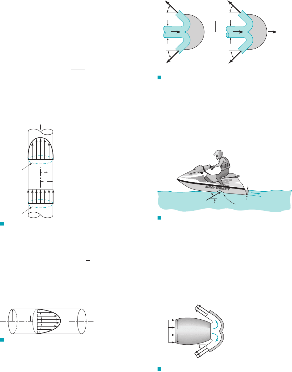
5.64 A Pelton wheel vane directs a horizontal, circular cross-
sectional jet of water symmetrically as indicated in Fig. P5.64 and
Video V5.6. The jet leaves the nozzle with a velocity of 100 ft兾s.
Determine the x direction component of anchoring force required
to (a) hold the vane stationary, (b) confine the speed of the vane to
a value of 10 ft兾s to the right. The fluid speed magnitude remains
constant along the vane surface.
5.65 How much power is transferred to the moving vane of Prob-
lem 5.64?
5.66 The thrust developed to propel the jet ski shown in Video
V9.11 and Fig. P5.66 is a result of water pumped through the vehi-
cle and exiting as a high-speed water jet. For the conditions shown
in the figure, what flowrate is needed to produce a 300-lb thrust?
Assume the inlet and outlet jets of water are free jets.
F I G U R E P5.64
45°
45°
D
= 1 in.
100
ft/s
(
a)
45°
45°
D = 1 in.
100
ft/s
10 ft/s
(
b)
y
x
F I G U R E P5.66
3.5-in.-diameter
outlet jet
30°
25-in.
2
inlet area
5.67 (See Fluids in the News article titled “Where the plume
goes,” Section 5.2.2.) Air flows into the jet engine shown in Fig.
P5.67 at a rate of 9 slugs/s and a speed of . Upon landing,
the engine exhaust exits through the reverse thrust mechanism
with a speed of in the direction indicated. Determine the
reverse thrust applied by the engine to the airplane. Assume
the inlet and exit pressures are atmospheric and that the mass
flowrate of fuel is negligible compared to the air flowrate through
the engine.
900 ft
Ⲑ
s
300 ft
Ⲑ
s
4-ft diameter
30°
(1)
(3)
(2)
V
1
= 300 ft/s
V
2
= 900 ft/s
V
3
= 900 ft/s
F I G U R E P5.67
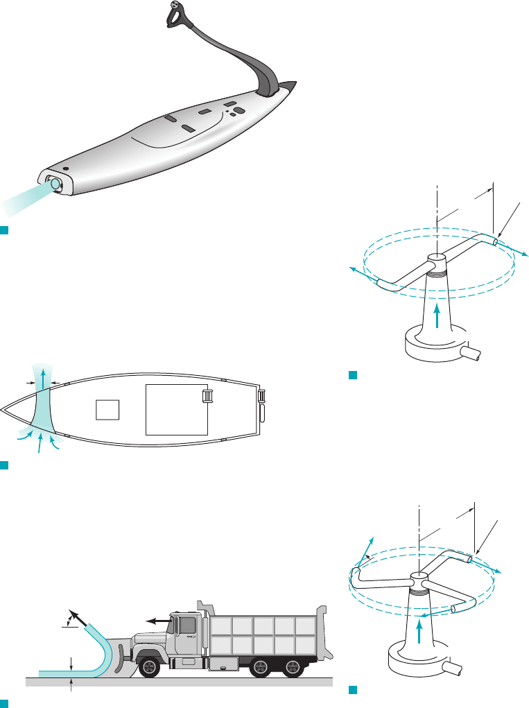
5.68 (See Fluids in the News article titled “Motorized surf-
board,” Section 5.2.2.) The thrust to propel the powered surfboard
shown in Fig. P5.68 is a result of water pumped through the board
that exits as a high-speed 2.75-in.-diameter jet. Determine the
flowrate and the velocity of the exiting jet if the thrust is to be
300 lb. Neglect the momentum of the water entering the pump.
JWCL068_ch05_187-262.qxd 9/23/08 10:20 AM Page 253
5.69 (See Fluids in the News article titled “Bow thrusters,” Sec-
tion 5.2.2). The bow thruster on the boat shown in Fig. P5.69 is
used to turn the boat. The thruster produces a 1-m-diameter jet of
water with a velocity of . Determine the force produced by
the thruster. Assume that the inlet and outlet pressures are zero and
that the momentum of the water entering the thruster is negligible.
10 m
s
254 Chapter 5 ■ Finite Control Volume Analysis
F I G U R E P5.68
V = 10 m/s
D = 1 m
F I G U R E P5.69
= 45°
(in plane of blade)
d = 8 in.
θ
U = 30 mph
F I G U R E P5.70
5.70 A snowplow mounted on a truck clears a path 12 ft through
heavy wet snow, as shown in Figure P5.70. The snow is 8 in. deep
and its density is 10 lbm/ft
3
. The truck travels at 30 mph. The snow
is discharged from the plow at an angle of 45 from the direction of
travel and 45 above the horizontal, as shown in Figure P5.70. Esti-
mate the force required to push the plow.
Section 5.2.3 Derivation of the Moment-of-Momentum
Equation
5.71 What is fluid moment-of-momentum (angular momentum)
and the “flow” of moment-of-momentum (angular momentum)?
5.72 Describe the orthogonal components of the moment-of-
momentum equation (Eq. 5.42) and comment on the direction of each.
5.73 Describe a few examples (include photographs/images) of
turbines where the force/torque of a flowing fluid leads to rotation
of a shaft.
5.74 Describe a few examples (include photographs/images) of
pumps where a fluid is forced to move by “blades” mounted on a
rotating shaft.
Section 5.2.4 Application of the Moment-of-Momentum
Equation
5.75 Water enters a rotating lawn sprinkler through its base at the
steady rate of 16 gal/min as shown in Fig. P5.75. The exit cross-
sectional area of each of the two nozzles is and the flow
leaving each nozzle is tangential. The radius from the axis of rotation
to the centerline of each nozzle is 8 in. (a) Determine the resisting
torque required to hold the sprinkler head stationary. (b) Determine
the resisting torque associated with the sprinkler rotating with a con-
stant speed of 500 rev兾min. (c) Determine the angular velocity of the
sprinkler if no resisting torque is applied.
0.04 in.
2
,
Q = 16 gal/min
r = 8 in.
Nozzle exit
area = 0.04 in.
2
F I G U R E P5.75
Q = 5 liters/s
r = 0.5m
Nozzle exit area normal to
relative velocity = 18 mm
2
θ
F I G U R E P5.76
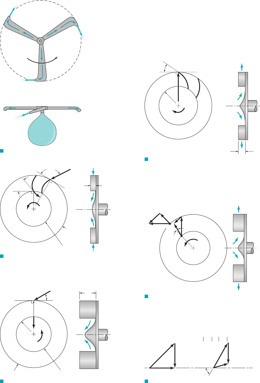
5.76 Five liters s of water enter the rotor shown in Video V5.10
and Fig. P5.76 along the axis of rotation. The cross-sectional area
of each of the three nozzle exits normal to the relative velocity is
How large is the resisting torque required to hold the rotor
stationary? How fast will the rotor spin steadily if the resisting
torque is reduced to zero and (a) (b) (c) u 60°?u 30°,u 0°,
18 mm
2
.
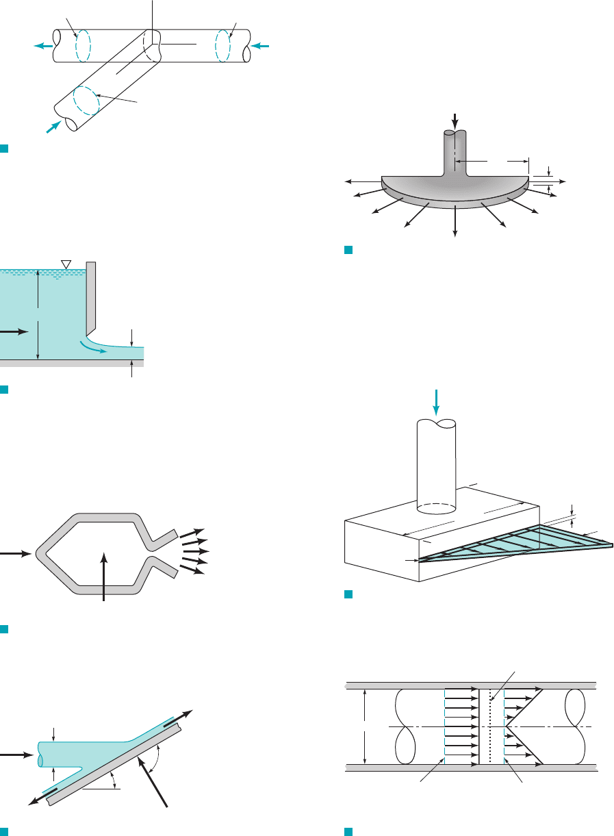
5.77 Shown in Fig. P5.77 is a toy “helicopter” powered by air
escaping from a balloon. The air from the balloon flows radially
through each of the three propeller blades and out through small
nozzles at the tips of the blades. Explain physically how this flow
can cause the rotation necessary to rotate the blades to produce the
needed lifting force.
5.78 A simplified sketch of a hydraulic turbine runner is shown in
Fig. P5.78. Relative to the rotating runner, water enters at section
(1) (cylindrical cross section area A
1
at r
1
1.5 m) at an angle of
100 from the tangential direction and leaves at section (2) (cylin-
drical cross section area A
2
at r
2
0.85 m ) at an angle of 50 from
the tangential direction. The blade height at sections (1) and (2) is
0.45 m and the volume flowrate through the turbine is 30 m
3
/s. The
runner speed is 130 rpm in the direction shown. Determine the shaft
power developed.
JWCL068_ch05_187-262.qxd 9/23/08 10:20 AM Page 254
5.79 A water turbine with radial flow has the dimensions shown in
Fig.P5.79.The absolute entering velocity is 50 ft/s, and it makes an
Problems
255
r
1
=
1.5 m
130
rpm
r
2
=
0.85 m
100°
50°
Section (1)
Section (2)
Q = 30 m
3
/s
0.45 m
W
2
W
1
F I G U R E P5.78
1 ft
Section (1)
Section (2)
r
1
= 2 ft
120
rpm
r
2
=
1 ft
V
2
V
1
= 50 ft/s
30°
F I G U R E P5.79
Balloon
ω
F I G U R E P5.77
angle of with the tangent to the rotor. The absolute exit veloc-
ity is directed radially inward. The angular speed of the rotor is 120
rpm. Find the power delivered to the shaft of the turbine.
5.80 Shown in Fig. P5.80 are front and side views of a centrifugal
pump rotor or impeller. If the pump delivers 200 liters/s of water
and the blade exit angle is 35 from the tangential direction, deter-
mine the power requirement associated with flow leaving at the
blade angle. The flow entering the rotor blade row is essentially ra-
dial as viewed from a stationary frame.
30°
r
1
=
9 cm
r
2
=
15 cm
35°
3000
rpm
3 cm
F I G U R E P5.80
W
2
= 16 m/s
W
1
V
1
V
2
U
2
=
16 m/s
U
1
= 8 m/s
30°
1
2
ω
F I G U R E P5.81
5.81 The velocity triangles for water flow through a radial pump
rotor are as indicated in Fig. P5.81. (a) Determine the energy added
to each unit mass (kg) of water as it flows through the rotor. (b)
Sketch an appropriate blade section.
5.82 An axial flow turbomachine rotor involves the upstream (1)
and downstream (2) velocity triangles shown in Fig.P5.82. Is this
turbomachine a turbine or a fan? Sketch an appropriate blade sec-
tion and determine energy transferred per unit mass of fluid.
U
1
= 30 ft/s
V
1
= 20 ft/s
=
60°
U
2
= 30 ft/s
W
1
W
1
W
2
1
W
2
F I G U R E P5.82
JWCL068_ch05_187-262.qxd 9/23/08 10:20 AM Page 255
5.83 An axial flow gasoline pump 1see Fig. P5.832consists of a ro-
tating row of blades 1rotor2followed downstream by a stationary row
of blades 1stator2. The gasoline enters the rotor axially 1without any an-
gular momentum2with an absolute velocity of 3 m兾s. The rotor blade
inlet and exit angles are and from the axial direction. The
pump annulus passage cross-sectional area is constant. Consider the
flow as being tangent to the blades involved. Sketch velocity triangles
for flow just upstream and downstream of the rotor and just down-
stream of the stator where the flow is axial. How much energy is
added to each kilogram of gasoline? Is this an actual or ideal amount?
45°60°
256 Chapter 5 ■ Finite Control Volume Analysis
U
V
1
= 3 m/s
60°
45°
Arithmetic
mean radius blade
sections
Rotor
Stator
F I G U R E P5.83
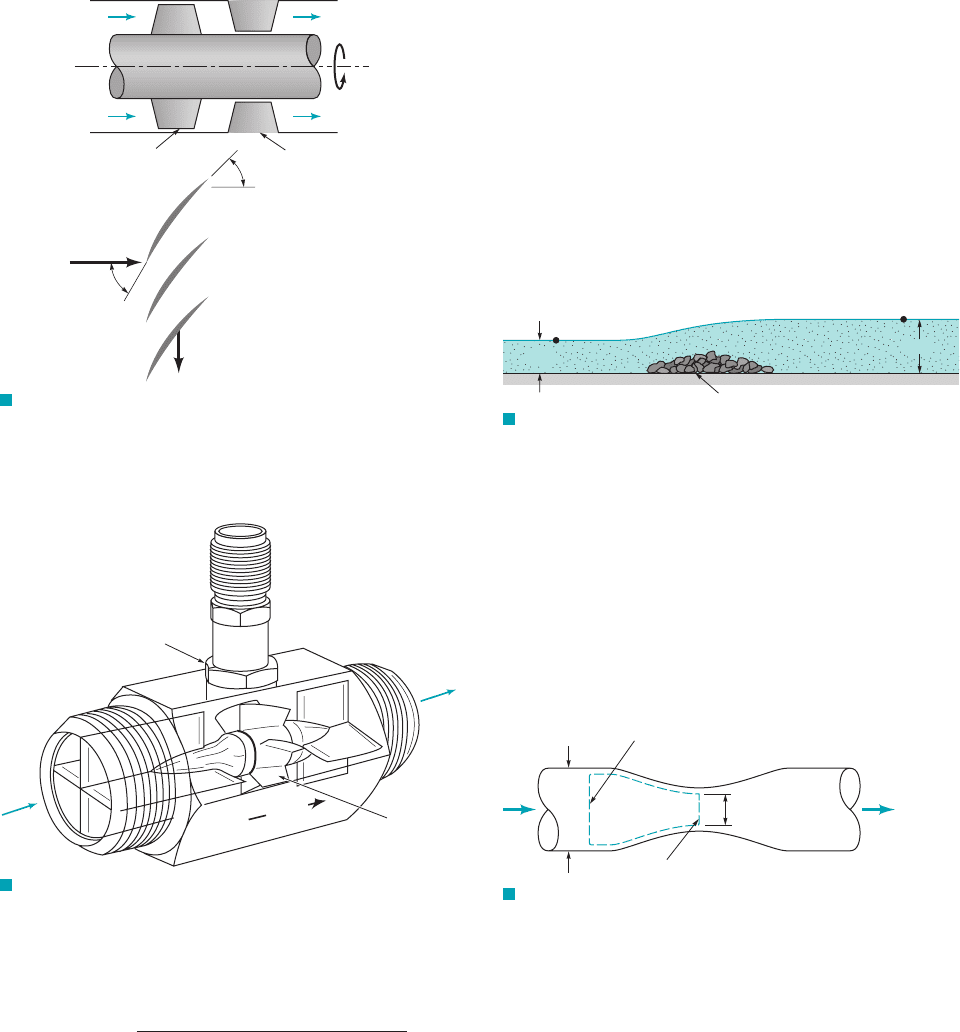
5.84 Sketch the velocity triangles for the flows entering and leaving
the rotor of the turbine-type flow meter shown in Fig. P5.84. Show
how rotor angular velocity is proportional to average fluid velocity.
FLOW
IN
OUT
Magnetic sensor
Turbine
Flow
in
Flow
out
F I G U R E P5.84 (Courtesy of EG&G Flow
Technology, Inc.)
5.85 By using velocity triangles for flow upstream 112and down-
stream 122of a turbomachine rotor, prove that the shaft work in per
unit mass flowing through the rotor is
where absolute flow velocity magnitude, relative flow
velocity magnitude, and blade speed.U ⫽
W ⫽V ⫽
w
shaft
net in
⫽
V
2
2
⫺ V
2
1
⫹ U
2
2
⫺ U
2
1
⫹ W
2
1
⫺ W
2
2
2
Section 5.3.1 Derivation of the Energy Equation
5.86 Distiguish between shaft work and other kinds of work asso-
ciated with a flowing fluid.
5.87 Define briefly what heat transfer is. What is an adiabatic
flow? Give several practical examples of nearly adiabatic flows.
Section 5.3.2 Application of the Energy Equation – No
Shaft Work and Section 5.3.3 Comparison of the Energy
Equation with the Bernoulli Equation
5.88 What is enthalpy and why is it useful for energy considera-
tions in fluid mechanics?
5.89 Cite a few examples of evidence of loss of available energy in
actual fluid flows. Why does loss occur?
5.90 Is zero heat transfer a necessary condition for application of
the Bernoulli equation (Eq. 5.75)?
5.91 A 1000-m-high waterfall involves steady flow from one large
body to another. Detemine the temperature rise associated with this
flow.
5.92 A 100-ft-wide river with a flowrate of flows over a
rock pile as shown in Fig. P5.92. Determine the direction of flow
and the head loss associated with the flow across the rock pile.
2400 ft
3
/s
(2)
2 ft
Rock pile
4 ft
(1)
F I G U R E P5.92
5.93 Air steadily expands adiabatically and without friction from
stagnation conditions of 690 kpa (abs) and 290 K to a static pres-
sure of 101 kpa (abs). Determine the velocity of the expanded air
assuming: (a) incompressible flow; (b) compressible flow.
5.94 A horizontal Venturi flow meter consists of a converging–di-
verging conduit as indicated in Fig. P5.94. The diameters of cross
sections (1) and (2) are 6 and 4 in. The velocity and static pressure
are uniformly distributed at cross sections (1) and (2). Determine
the volume flowrate (ft
3
/s) through the meter if ,
the flowing fluid is oil , and the loss per unit mass
from (1) to (2) is negligibly small.
1r ⫽ 56 lbm
Ⲑ
ft
3
2
p
1
⫺ p
2
⫽ 3 psi
Section (2)
Section (1)
D
1
= 6 in.
D
2
= 4 in.
F I G U R E P5.94
5.95 Oil flows downward through a vertical pipe con-
traction as shown in Fig. P5.95. If the mercury manometer reading,
h, is 100 mm, determine the volume flowrate for frictionless flow.
Is the actual flowrate more or less than the frictionless value?
Explain.
5.96 An incompressible liquid flows steadily along the pipe
shown in Fig. P5.96. Determine the direction of flow and the head
loss over the 6-m length of pipe.
1SG ⫽ 0.92
JWCL068_ch05_187-262.qxd 9/30/08 3:37 PM Page 256