Munson B.R. Fundamentals of Fluid Mechanics
Подождите немного. Документ загружается.

that the value of C is relatively insensitive to the shape of the conduit. Unless the cross section is
very “thin” in some sense, the value of C is not too different from its circular pipe value,
Once the friction factor is obtained, the calculations for noncircular conduits are identical to those
for round pipes.
Calculations for fully developed turbulent flow in ducts of noncircular cross section are usu-
ally carried out by using the Moody chart data for round pipes with the diameter replaced by the
hydraulic diameter and the Reynolds number based on the hydraulic diameter. Such calculations
are usually accurate to within about 15%. If greater accuracy is needed, a more detailed analysis
based on the specific geometry of interest is needed.
C 64.
8.4 Dimensional Analysis of Pipe Flow 427
The Moody chart,
developed for round
pipes, can also be
used for noncircu-
lar ducts.
GIVEN Air at a temperature of 120 ºF and standard pressure
flows from a furnace through an 8-in.-diameter pipe with an av-
erage velocity of 10 ft/s. It then passes through a transition sec-
tion similar to the one shown in Fig. E8.7 and into a square duct
whose side is of length a. The pipe and duct surfaces are smooth
. The head loss per foot is to be the same for the pipe and
the duct.
FIND Determine the duct size, a.
1e 02
Noncircular Conduit
E
XAMPLE 8.7
V
F I G U R E E8.7
S
OLUTION
where a is in feet. Similarly, the Reynolds number based on the
hydraulic diameter is
(4)
We have three unknowns 1a, f, and Re
h
2and three equations—
Eqs. 3, 4, and either in graphical form the Moody chart 1Fig. 8.202
or the Colebrook equation (Eq. 8.35a).
If we use the Moody chart, we can use a trial and error solution
as follows. As an initial attempt, assume the friction factor for the
duct is the same as for the pipe. That is, assume From
Eq. 3 we obtain while from Eq. 4 we have
From Fig. 8.20, with this Reynolds number
and the given smooth duct we obtain which does not
quite agree with the assumed value of f. Hence, we do not have the
solution. We try again, using the latest calculated value of
as our guess. The calculations are repeated until the
guessed value of f agrees with the value obtained from Fig. 8.20.
The final result 1after only two iterations2 is
and
(Ans)
COMMENTS Alternatively, we can use the Colebrook equa-
tion (rather than the Moody chart) to obtain the solution as
a 0.611 ft 7.34 in.
Re
h
3.03 10
4
,
f 0.023,
f 0.023
f 0.023,
Re
h
3.05 10
4
.
a 0.606 ft,
f 0.022.
Re
h
V
s
D
h
n
13.49
a
2
2a
1.89 10
4
1.85 10
4
a
We first determine the head loss per foot for the pipe,
and then size the square duct to give the
same value. For the given pressure and temperature we obtain
1from Table B.32 so that
With this Reynolds number and with we obtain the fric-
tion factor from Fig. 8.20 as so that
Thus, for the square duct we must have
(1)
where
(2)
is the velocity in the duct.
By combining Eqs. 1 and 2 we obtain
or
(3)a 1.30 f
1
5
0.0512
f
a
13.49
a
2
2
2
2132.22
V
s
Q
A
p
4
a
8
12
ftb
2
110 ft
s2
a
2
3.49
a
2
D
h
4A
P 4a
2
4a a
and
h
L
/
f
D
h
V
2
s
2g
0.0512
h
L
/
0.022
1
8
12
ft2
110 ft
s2
2
2132.2 ft
s
2
2
0.0512
f 0.022
e
D 0
Re
VD
n
110 ft
s21
8
12
ft2
1.89 10
4
ft
2
s
35,300
n 1.89 10
4
ft
2
s
h
L
/ 1f
D2 V
2
2g,
JWCL068_ch08_383-460.qxd 9/23/08 10:55 AM Page 427

8.5 Pipe Flow Examples
428 Chapter 8 ■ Viscous Flow in Pipes
follows. For a smooth pipe the Colebrook equation,
Eq. 8.35a, becomes
(5)
where from Eq. 3,
(6)
If we combine Eqs. 4, 5, and 6 and simplify, Eq. 7 is obtained for a.
(7)1.928 a
⫺5
Ⲑ
2
⫽⫺2 log12.62 ⫻ 10
⫺4
a
⫺3
Ⲑ
2
2
f ⫽ 0.269 a
5
⫽⫺2.0 log a
2.51
Re
h
1f
b
1
1f
⫽⫺2.0 log a
e
Ⲑ
D
h
3.7
⫹
2.51
Re
h
1f
b
1e
Ⲑ
D
h
⫽ 02
By using a root-finding technique on a computer or calculator, the
solution to Eq. 7 is determined to be , in agreement
(given the accuracy of reading the Moody chart) with that ob-
tained by the trial and error method given above.
Note that the length of the side of the equivalent square duct
is or approximately 92% of the diameter
of the equivalent duct. It can be shown that this value, 92%, is a
very good approximation for any pipe flow—laminar or turbu-
lent. The cross-sectional area of the duct is
greater than that of the round pipe Also,
it takes less material to form the round pipe
than the square duct Cir-
cles are very efficient shapes.
1perimeter ⫽ 4a ⫽ 29.4 in.2.25.1 in.2
1perimeter ⫽ pD ⫽
1A ⫽ pD
2
Ⲑ
4 ⫽ 50.3 in.
2
2.
1A ⫽ a
2
⫽ 53.9 in.
2
2
a
Ⲑ
D ⫽ 7.34
Ⲑ
8 ⫽ 0.918,
a ⫽ 0.614 ft
In the previous sections of this chapter, we discussed concepts concerning flow in pipes and ducts.
The purpose of this section is to apply these ideas to the solutions of various practical problems.
The application of the pertinent equations is straightforward, with rather simple calculations that
give answers to problems of engineering importance. The main idea involved is to apply the en-
ergy equation between appropriate locations within the flow system, with the head loss written in
terms of the friction factor and the minor loss coefficients. We will consider two classes of pipe
systems: those containing a single pipe 1whose length may be interrupted by various components2,
and those containing multiple pipes in parallel, series, or network configurations.
Pipe systems may
contain a single
pipe with compo-
nents or multiple
interconnected
pipes.
Fluids in the News
New hi-tech fountains Ancient Egyptians used fountains in
their palaces for decorative and cooling purposes. Current use of
fountains continues, but with a hi-tech flair. Although the basic
fountain still consists of a typical pipe system (i.e., pump, pipe,
regulating valve, nozzle, filter, and basin), recent use of computer-
controlled devices has led to the design of innovative fountains
with special effects. For example, by using several rows of multi-
ple nozzles, it is possible to program and activate control valves to
produce water jets that resemble symbols, letters, or the time of
day. Other fountains use specially designed nozzles to produce
coherent, laminar streams of water that look like glass rods flying
through the air. By using fast-acting control valves in a synchronized
manner it is possible to produce mesmerizing three-dimensional
patterns of water droplets. The possibilities are nearly limitless.
With the initial artistic design of the fountain established, the ini-
tial engineering design (i.e., the capacity and pressure require-
ments of the nozzles and the size of the pipes and pumps) can be
carried out. It is often necessary to modify the artistic and
/
or en-
gineering aspects of the design in order to obtain a functional,
pleasing fountain. (See Problem 8.64.)
8.5.1 Single Pipes
The nature of the solution process for pipe flow problems can depend strongly on which of the var-
ious parameters are independent parameters 1the “given”2and which is the dependent parameter 1the
“determine”2. The three most common types of problems are shown in Table 8.4 in terms of the pa-
rameters involved. We assume the pipe system is defined in terms of the length of pipe sections used
and the number of elbows, bends, and valves needed to convey the fluid between the desired loca-
tions. In all instances we assume the fluid properties are given.
In a Type I problem we specify the desired flowrate or average velocity and determine the
necessary pressure difference or head loss. For example, if a flowrate of 2.0 gal兾min is required
for a dishwasher that is connected to the water heater by a given pipe system as shown by the fig-
ure in the margin, what pressure is needed in the water heater?
In a Type II problem we specify the applied driving pressure 1or, alternatively, the head loss2
and determine the flowrate. For example, how many gal兾min of hot water are supplied to the dish-
washer if the pressure within the water heater is 60 psi and the pipe system details 1length, diam-
eter, roughness of the pipe; number of elbows; etc.2are specified?
I: Δp = ?
III: D = ?
II: Q = ?
JWCL068_ch08_383-460.qxd 9/23/08 10:55 AM Page 428
In a Type III problem we specify the pressure drop and the flowrate and determine the diame-
ter of the pipe needed. For example, what diameter of pipe is needed between the water heater and
dishwasher if the pressure in the water heater is 60 psi 1determined by the city water system2and the
flowrate is to be not less than 2.0 gal兾min 1determined by the manufacturer2?
Several examples of these types of problems follow.
8.5 Pipe Flow Examples 429
■ TABLE 8.4
Pipe Flow Types
Variable Type I Type II Type III
a. Fluid
Density Given Given Given
Viscosity Given Given Given
b. Pipe
Diameter Given Given Determine
Length Given Given Given
Roughness Given Given Given
c. Flow
Flowrate or Given Determine Given
Average Velocity
d. Pressure
Pressure Drop or Determine Given Given
Head Loss
Pipe flow problems
can be categorized
by what parameters
are given and what
is to be calculated.
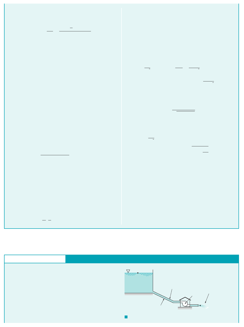
GIVEN Water at 60 ºF flows from the basement to the second
floor through the 0.75-in. (0.0625-ft)-diameter copper pipe
(a drawn tubing) at a rate of
and exits through a faucet of diameter 0.50 in. as shown in Fig.
E8.8a.
FIND Determine the pressure at point (1) if
(a) all losses are neglected,
(b) the only losses included are major losses, or
(c) all losses are included.
Q ⫽ 12.0 gal
Ⲑ
min ⫽ 0.0267 ft
3
Ⲑ
s
Type I, Determine Pressure Drop
E
XAMPLE 8.8
S
OLUTION
(1)
where the head loss is different for each of the three cases.
(a) If all losses are neglected Eq. 1 gives
or
(Ans)
p
1
⫽ 10.7 psi
⫽ 11248 ⫹ 2992 lb
Ⲑ
ft
2
⫽ 1547 lb
Ⲑ
ft
2
⫹
1.94 slugs
Ⲑ
ft
3
2
ca19.6
ft
s
b
2
⫺ a8.70
ft
s
b
2
d
p
1
⫽ 162.4 lb
Ⲑ
ft
3
2120 ft2
1h
L
⫽ 02,
p
1
⫽ gz
2
⫹
1
2
r1V
2
2
⫺ V
2
1
2⫹ gh
L
Since the fluid velocity in the pipe is given by
and the
fluid properties are and
1see Table B.12, it follows that
Thus, the flow is turbulent. The governing equation for either case
1a2, 1b2, or 1c2is the energy equation given by Eq. 8.21,
where lbⲐft
3
,
and the outlet velocity is
We assume that the kinetic energy coeffi-
cients and are unity. This is reasonable because turbulent ve-
locity profiles are nearly uniform across the pipe. Thus,
a
2
a
1
⫽ 19.6 ft
Ⲑ
s.122
2
ft
2
Ⲑ
44
3p10.50
Ⲑ
V
2
⫽ Q
Ⲑ
A
2
⫽ 10.0267 ft
3
Ⲑ
s2
Ⲑ
z
1
⫽ 0, z
2
⫽ 20 ft, p
2
⫽ 0 1free jet2, g ⫽ rg ⫽ 62.4
p
1
g
⫹ a
1
V
2
1
2g
⫹ z
1
⫽
p
2
g
⫹ a
2
V
2
2
2g
⫹ z
2
⫹ h
L
lb
#
s
Ⲑ
ft
2
2⫽ 45,000.slugs
Ⲑ
ft
3
218.70 ft
Ⲑ
s210.0625 ft2
Ⲑ
12.34 ⫻ 10
⫺5
rVD
Ⲑ
m ⫽ 11.94
Re ⫽10
⫺5
lb
#
s
Ⲑ
ft
2
m ⫽ 2.34 ⫻
r ⫽ 1.94 slugs
Ⲑ
ft
3
ft
3
Ⲑ
s2
Ⲑ
3p10.0625 ft2
2
Ⲑ
44⫽ 8.70 ft
Ⲑ
s,Q
Ⲑ
1pD
2
Ⲑ
42⫽ 10.0267
V
1
⫽ Q
Ⲑ
A
1
⫽
Q =
12.0
gal/min
(1)
(2)
(3)
15 ft
10 ft
5 ft
10 ft
10 ft 10 ft
(8)(7)
(6)
(4)
(5)
g
Threaded
90° elbows
0.75-in.-diameter
copper pipe
Wide open
globe valve
0.50-in.
diameter
K
L
= 2 based on
pipe
velocity
F I G U R E E8.8
a
JWCL068_ch08_383-460.qxd 9/23/08 10:55 AM Page 429
430 Chapter 8 ■ Viscous Flow in Pipes
COMMENT Note that for this pressure drop, the amount due
to elevation change 1the hydrostatic effect2is
and the amount due to the increase in kinetic energy is
(b) If the only losses included are the major losses, the head
loss is
From Table 8.1 the roughness for a 0.75-in.-diameter copper
pipe 1drawn tubing2is so that
With this and the calculated Reynolds number
the value of f is obtained from the Moody chart as
Note that the Colebrook equation 1Eq. 8.352would
give the same value of f. Hence, with the total length of the pipe
as and the elevation
and kinetic energy portions the same as for part 1a2, Eq. 1 gives
or
(Ans)
COMMENT Of this pressure drop, the amount due to pipe
friction is approximately
(c) If major and minor losses are included, Eq. 1 becomes
or
(2)
where the 21.3 psi contribution is due to elevation change, kinetic
energy change, and major losses [part 1b2], and the last term rep-
resents the sum of all of the minor losses. The loss coefficients of
the components 1 for each elbow and for the
wide-open globe valve2are given in Table 8.2 1except for the loss
coefficient of the faucet, which is given in Fig. E8.8a as 2.
Thus,
or
(3)
Note that we did not include an entrance or exit loss because points
112and 122are located within the fluid streams, not within an at-
a
rK
L
V
2
2
⫽ 9.17 psi
⫽ 1321 lb
Ⲑ
ft
2
a
rK
L
V
2
2
⫽ 11.94 slugs
Ⲑ
ft
3
2
18.70 ft2
2
2
310 ⫹ 411.52⫹ 24
K
L
⫽ 2
K
L
⫽ 10K
L
⫽ 1.5
p
1
⫽ 21.3 psi ⫹
a
rK
L
V
2
2
p
1
⫽ gz
2
⫹
1
2
r1V
2
2
⫺ V
2
1
2⫹ fg
/
D
V
2
1
2g
⫹
a
rK
L
V
2
2
psi ⫽ 10.6 psi.121.3 ⫺ 10.72
p
1
⫽ 21.3 psi
⫽ 11248 ⫹ 299 ⫹ 15152 lb
Ⲑ
ft
2
⫽ 3062 lb
Ⲑ
ft
2
⫹ 11.94 slugs
Ⲑ
ft
3
210.02152 a
60 ft
0.0625 ft
b
18.70 ft
Ⲑ
s2
2
2
⫽ 11248 ⫹ 2992 lb
Ⲑ
ft
2
p
1
⫽ gz
2
⫹
1
2
r1V
2
2
⫺ V
2
1
2⫹ rf
/
D
V
2
1
2
⫽ 60 ft/ ⫽ 115 ⫹ 5 ⫹ 10 ⫹ 10 ⫹ 202 ft
f ⫽ 0.0215.
45,0002,
1Re ⫽
e
Ⲑ
D
e
Ⲑ
D ⫽ 8 ⫻ 10
⫺5
.
e ⫽ 0.000005 ft
h
L
⫽ f
/
D
V
1
2
2g
2.07 psi.
r1V
2
2
⫺ V
2
1
2
Ⲑ
2 ⫽
g1z
2
⫺ z
1
2⫽ 8.67 psi
taching reservoir where the kinetic energy is zero. Thus, by com-
bining Eqs. 2 and 3 we obtain the entire pressure drop as
(Ans)
This pressure drop calculated by including all losses should be the
most realistic answer of the three cases considered.
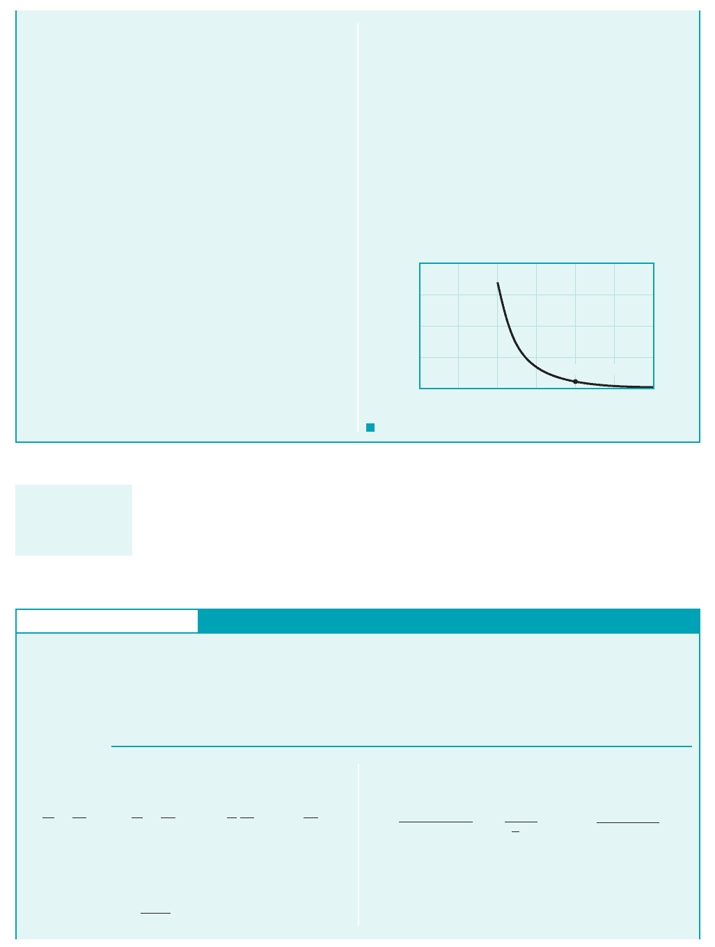
COMMENTS More detailed calculations will show that the
pressure distribution along the pipe is as illustrated in Fig. E8.8b
for cases 1a2and 1c2—neglecting all losses or including all losses.
Note that not all of the pressure drop, is a “pressure
loss.” The pressure change due to the elevation and velocity
changes is completely reversible. The portion due to the major
and minor losses is irreversible.
This flow can be illustrated in terms of the energy line and hy-
draulic grade line concepts introduced in Section 3.7. As is shown
in Fig. E8.8c, for case 1a2there are no losses and the energy line
1EL2is horizontal, one velocity head above the hydraulic
grade line 1HGL2, which is one pressure head above the pipe
itself. For cases 1b2or 1c2the energy line is not horizontal. Each bit
of friction in the pipe or loss in a component reduces the available
1gz2
1V
2
Ⲑ
2g2
p
1
⫺ p
2
,
p
1
⫽ 121.3 ⫹ 9.172 psi ⫽ 30.5 psi
80
60
40
20
0
0 10 20 30 40 50 60
Distance along pipe from point (1), ft
H, elevation to energy line, ft
Energy line with no losses, case (a)
Energy line including all
losses, case (
c)
Sharp drop due to component loss
Slope due to pipe friction
F I G U R E E8.8
c
F I G U R E E8.8
b
30
20
10
0
0 10 20 30 40 50 60
10.7
10.7
6.37
2.07
2.07
4.84
3.09
9.93
12.4
11.7
30.5 psi
27.1
27.8
20.2
21.0
18.5
19.3
(
a) No losses
(
c) Including all
losses
Pressure
loss
Elevation
and
kinetic
energy
p
2
= 0
Distance along pipe from point (1), ft
p, psi
Location: (1) (3) (4) (5) (6) (7) (8) (2)
6.37
JWCL068_ch08_383-460.qxd 9/23/08 10:56 AM Page 430
Although the governing pipe flow equations are quite simple, they can provide very reason-
able results for a variety of applications, as is shown in the next example.
8.5 Pipe Flow Examples 431
energy, thereby lowering the energy line. Thus, for case 1a2the to-
tal head remains constant throughout the flow with a value of
For case 1c2the energy line starts at
and falls to a final value of
26.0 ft
H
2
p
2
g
V
2
2
2g
z
2
0
119.6 ft
s2
2
2132.2 ft
s
2
2
20 ft
130.5 1442lb
ft
2
162.4 lb
ft
3
2
18.70 ft
s2
2
2132.2 ft
s
2
2
0 71.6 ft
H
1
p
1
g
V
2
1
2g
z
1
p
2
g
V
2
2
2g
z
2
p
3
g
V
3
3
2g
z
3
p
26.0 ft.
H
p
1
g
V
2
1
2g
z
1
11547 lb
ft
2
2
162.4 lb
ft
3
2
18.70 ft
s2
2
2132.2 ft
s
2
2
0
The elevation of the energy line can be calculated at any point
along the pipe. For example, at point 172, 50 ft from point 112,
The head loss per foot of pipe is the same all along the pipe.
That is,
Thus, the energy line is a set of straight line segments of the same
slope separated by steps whose height equals the head loss of the
minor component at that location. As is seen from Fig. E8.8c, the
globe valve produces the largest of all the minor losses.
h
L
/
f
V
2
2gD
0.021518.70 ft
s2
2
2132.2 ft
s
2
210.0625 ft2
0.404 ft
ft
44.1 ft
19.93 1442 lb
ft
2
162.4 lb
ft
3
2
18.70 ft
s2
2
2132.2 ft
s
2
2
20 ft
H
7
p
7
g
V
2
7
2g
z
7
GIVEN As shown in Fig. E8.9a, crude oil at 140 °F with ␥
53.7 lb ft
3
and 8 10
5
lb s ft
2
(about four times the vis-
cosity of water) is pumped across Alaska through the Alaskan
pipeline, a 799-mile-long, 4-ft-diameter steel pipe, at a maxi-
mum rate of Q 2.4 million barrels day 117 ft
3
s.
FIND Determine the horsepower needed for the pumps that
drive this large system.
Type I, Determine Head Loss
E
XAMPLE 8.9
S
OLUTION
1see Table 8.12and
Thus,
and the actual power supplied to the fluid, is
(Ans)
COMMENTS
There are many reasons why it is not practical
to drive this flow with a single pump of this size. First, there are no
pumps this large! Second, the pressure at the pump outlet would
202,000 hp
1.11 10
8
ft
#
lb
s a
1 hp
550 ft
#
lb
s
b
p
a
gQh
p
153.7 lb
ft
3
21117 ft
3
s2117,700 ft2
p
a
,
h
p
0.012511.05 10
6
2
19.31 ft
s2
2
2132.2 ft
s
2
2
17,700 ft
7.76 10
5
.s
ft
2
2
19.31 ft
s214.0 ft2
18 10
5
lb
#
slugs
ft
3
4
m 3153.7
32.22Re rVD
0.0000375
From the energy equation 1Eq. 8.212we obtain
where points 112and 122represent locations within the large hold-
ing tanks at either end of the line and is the head provided to the
oil by the pumps. We assume that 1pumped from sea level
to sea level2, 1large, open tanks2and
Minor losses are negligible because of the
large length-to-diameter ratio of the relatively straight, uninterrupted
pipe;
Thus,
where V QA (117 ft
3
s) From Fig.
8.20 or Eq. 8.35, since 10.00015 ft2
14 ft2e
D f 0.0125
3p14 ft2
2
44 9.31 ft
s.
h
p
h
L
f
/
D
V
2
2g
1.05 10
6
.mi2
14 ft215280 ft
/
D 1799 mi2
1
f/
D2V
2
2g.h
L
V
1
V
2
0p
1
p
2
z
1
z
2
h
p
p
1
g
V
2
1
2g
z
1
h
p
p
2
g
V
2
2
2g
z
2
h
L
Pump
Oil:
= 53.7 lb/ft
3
= 8 10
5
lbf
.
s/ft
2
4-ft-diameter,
799-mile-long
steel pipe
Prudhoe Bay, Alaska
(1)
(2)
Valdez, Alaska
F I G U R E E8.9
a
JWCL068_ch08_383-460.qxd 9/23/08 10:56 AM Page 431
Pipe flow problems in which it is desired to determine the flowrate for a given set of condi-
tions 1Type II problems2often require trial-and-error or numerical root-finding techniques. This is
because it is necessary to know the value of the friction factor to carry out the calculations, but
the friction factor is a function of the unknown velocity 1flowrate2in terms of the Reynolds num-
ber. The solution procedure is indicated in Example 8.10.
432 Chapter 8 ■ Viscous Flow in Pipes
need to be
No practical 4-ft-diameter pipe would withstand this
pressure. An equally unfeasible alternative would be to place the
holding tank at the beginning of the pipe on top of a hill of height
and let gravity force the oil through the 799-mi
pipe! How much power would it take to lift the oil to the top of the
hill?
To produce the desired flow, the actual system contains 12
pumping stations positioned at strategic locations along the
pipeline. Each station contains four pumps, three of which oper-
ate at any one time 1the fourth is in reserve in case of emergency2.
Each pump is driven by a 13,500-hp motor, thereby producing a
total horsepower of stations 2
If we assume that the combi-
nation is approximately 60% efficient, there is a total of
available to drive the fluid. This
number compares favorably with the 202,000-hp answer calcu-
lated above.
The assumption of a oil temperature may not seem reason-
able for flow across Alaska. Note, however, that the oil is warm when
it is pumped from the ground and that the 202,000 hp needed to pump
the oil is dissipated as a head loss 1and therefore a temperature rise2
along the pipe. However, if the oil temperature were rather than
, the viscosity would be approximately
1twice as large2, but the friction factor would only increase from
at to at
This doubling of viscosity would result in
70 °F 1Re 3.88 10
5
2.
f 0.0140140 °F 1Re 7.76 10
5
2f 0.0125
16 10
5
lb
#
s
ft
2
140 °F
70 °F
140 °F
0.60 1486,0002 hp 292,000 hp
motorpump
pump2 486,000 hp.
113,500 hp
station
13 pump
p 12
h
L
17,700 ft
6600 psi.
11 ft
2
144 in.
2
2p gh
L
153.7 lb
ft
3
2117,700 ft2
only an 11% increase in power 1from 202,000 to 226,000 hp2. Because
of the large Reynolds numbers involved, the shear stress is due mostly
to the turbulent nature of the flow. That is, the value of Re for this flow
is large enough 1on the relatively flat part of the Moody chart2so that f
is nearly independent of Re 1or viscosity2.
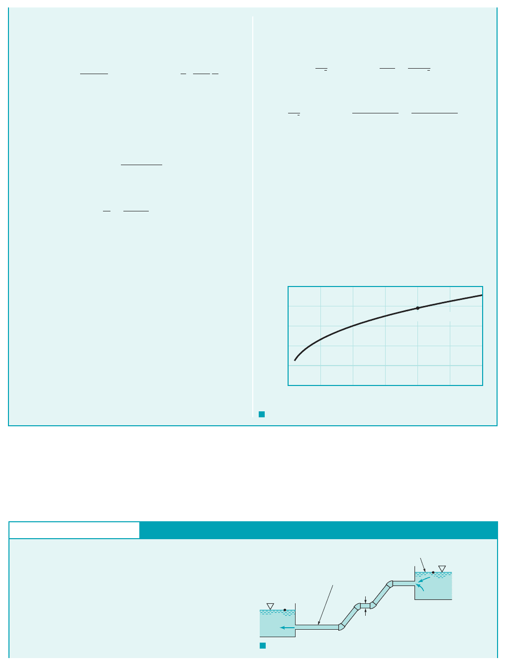
By repeating the calculations for various values of the pipe di-
ameter, D, the results shown in Fig. E8.9b are obtained. Clearly the
required pump power, is a strong function of the pipe diameter,
with if the friction factor is constant. The actual 4-ft-
diameter pipe used represents a compromise between using smaller
diameter pipes which are less expensive to make but require consid-
erably more pump power, and larger diameter pipes which require
less pump power but are very expensive to make and maintain.
p
a
~ D
4
p
a
,
4 × 10
6
3 × 10
6
2 × 10
6
1 × 10
6
0
0123456
(4 ft, 2.02 × 10
5
hp)
D, ft
ᏼ
a
, hp
F I G U R E E8.9
b
GIVEN Air at a temperature of 100 °F and standard pressure
flows from a clothes dryer. According to the appliance manufac-
turer, the 4-in.-diameter galvanized iron vent on the clothes dryer is
not to contain more than 20 ft of pipe and four 90 elbows.
FIND Under these conditions determine the air flowrate if the
pressure at the start of the vent pipe, directly downstream of the
dryer fan, is 0.20 in. of water.
Type II, Determine Flowrate
E
XAMPLE 8.10
S
OLUTION
Thus, with 1see Table B.32and 1the air
velocity in the pipe2, Eq. 1 becomes
or
(2)
where V is in
ft
s.
945 16.0 60 f 2V
2
411.52d
V
2
2132.2 ft
s
2
2
11.04 lb
ft
2
2
10.0709 lb
ft
3
2
cf
120 ft2
1
4
12
ft2
V
2
V
g 0.0709 lb
ft
3
Application of the energy equation 1Eq. 8.212between the beginning
of the vent pipe, point 112, and the exit of the pipe, point 122, gives
(1)
where for each elbow is assumed to be 1.5. In addition,
and 1The change in elevation is often negligible
for gas flows.2Also, and or
p
1
10.2 in.2 a
1 ft
12 in.
b 162.4 lb
ft
3
2 1.04 lb
ft
2
p
1
g
H
2
O
0.2 in.,
p
2
0,
z
1
z
2
.V
1
V
2
K
L
p
1
g
V
2
1
2g
z
1
p
2
g
V
2
2
2g
z
2
f
/
D
V
2
2g
a
K
L
V
2
2g
Some pipe flow
problems require a
trial-and-error solu-
tion technique.
JWCL068_ch08_383-460.qxd 9/23/08 10:57 AM Page 432
8.5 Pipe Flow Examples 433
The value of f is dependent on Re, which is dependent on V,
an unknown. However, from Table B.3, and
we obtain
or
(3)
where again V is in
Also, since 1see Table
8.1 for the value of 2, we know which particular curve of the
Moody chart is pertinent to this flow. Thus, we have three rela-
tionships 1Eqs. 2, 3, and the curve of Fig. 8.202
from which we can solve for the three unknowns f, Re, and V.
This is done easily by an iterative scheme as follows.
It is usually simplest to assume a value of f, calculate Vfrom Eq.
2, calculate Re from Eq. 3, and look up the appropriate value of f in
the Moody chart for this value of Re. If the assumed f and the new f
do not agree, the assumed answer is not correct—we do not have the
solution to the three equations. Although values of either f, V, or Re
could be assumed as starting values, it is usually simplest to assume
a value of f because the correct value often lies on the relatively flat
portion of the Moody chart for which f is quite insensitive to Re.
Thus, we assume approximately the large Re limit
for the given relative roughness. From Eq. 2 we obtain
and from Eq. 3
With this Re and Fig. 8.20 gives which is not
equal to the assumed solution 1although it is close!2.
We try again, this time with the newly obtained value of
which gives and With
these values, Fig. 8.20 gives which agrees with the as-
sumed value. Thus, the solution is or
(Ans)Q AV
p
4
1
4
12
ft2
2
111.0 ft
s2 0.960 ft
3
s
V 11.0 ft
s,
f 0.029,
Re 20,500.V 11.0 ft
sf 0.029,
f 0.022
f 0.029,
e
D,
Re 1860111.42 21,200
V c
945
6.0 6010.0222
d
1
2
11.4 ft
s
f 0.022,
e
D 0.0015
e
e
D 10.0005 ft2
14
12 ft2 0.0015
ft
s.
Re 1860 V
Re
VD
n
1
4
12
ft2 V
1.79 10
4
ft
2
s
n 1.79 10
4
ft
2
s
COMMENTS Note that the need for the iteration scheme is
because one of the equations, is in graphical
form 1the Moody chart2. If the dependence of f on Re and is
known in equation form, this graphical dependency is elimi-
nated, and the solution technique may be easier. Such is the case
if the flow is laminar so that the friction factor is simply
For turbulent flow, we can use the Colebrook equa-
tion rather than the Moody chart. Thus, we keep Eqs. 2 and 3
and use the Colebrook equation 1Eq. 8.35a) with
to give
(4)
From Eq. 2 we have which can be
combined with Eq. 3 to give
(5)
The combination of Eqs. 4 and 5 provides a single equation for
the determination of f
(6)
By using a root-finding technique on a computer or calculator,
the solution to this equation is determined to be in
agreement with the above solution which used the Moody
chart.
Note that unlike the Alaskan pipeline example 1Example
8.92in which we assumed minor losses are negligible, minor
losses are of importance in this example because of the rela-
tively small length-to-diameter ratio:
The ratio of minor to major losses in this case is
The elbows and entrance produce
considerably more loss than the pipe itself.
6.0
30.029 16024 3.45.
K
L
1f/
D2
/
D 20
14
122 60.
f 0.029,
4.39 10
5
B
60
6.0
f
b
1
1f
2.0 log a4.05 10
4
Re
57,200
16.0 60 f
V 3945
16.0 60 f 24
1
2
,
2.0 log a4.05 10
4
2.51
Re1f
b
1
1f
2.0 log a
e
D
3.7
2.51
Re1f
b
e
D 0.0015
f 64
Re.
e
D
f f1Re, e
D2,
GIVEN The turbine shown in Fig. E8.11 extracts 50 hp from
the water flowing through it. The 1-ft-diameter, 300-ft-long
pipe is assumed to have a friction factor of 0.02. Minor losses
are negligible.
FIND Determine the flowrate through the pipe and turbine.
Type II, Determine Flowrate
E
XAMPLE 8.11
(2)
Free jet
Turbine
300-ft-long,
1-ft-diameter pipe
(1)
f = 0.02
z
2
= 0
z
1
= 90 ft
F I G U R E E8.11
JWCL068_ch08_383-460.qxd 9/23/08 10:57 AM Page 433

In pipe flow problems for which the diameter is the unknown 1Type III2, an iterative or numer-
ical root-finding technique is required. This is, again, because the friction factor is a function of the
diameter—through both the Reynolds number and the relative roughness. Thus, neither
are known unless D is known. Examples 8.12 and 8.13 illustrate this.4rQ
Ⲑ
pmD nor e
Ⲑ
D
Re ⫽ rVD
Ⲑ
m ⫽
434 Chapter 8 ■ Viscous Flow in Pipes
S
OLUTION
and has no physical meaning for this flow.
Thus, the two acceptable flowrates are
(Ans)
or
(Ans)
COMMENTS Either of these two flowrates gives the same
power, The reason for two possible solutions can be
seen from the following. With the low flowrate we
obtain the head loss and turbine head as and
Because of the relatively low velocity there is a rela-
tively small head loss and, therefore, a large head available for the
turbine. With the large flowrate we find
and The high-speed flow in the pipe pro-
duces a relatively large loss due to friction, leaving a relatively small
head for the turbine. However, in either case the product of the tur-
bine head times the flowrate is the same. That is, the power extracted
is identical for each case. Although either flowrate
will allow the extraction of 50 hp from the water, the details of the
design of the turbine itself will depend strongly on which flowrate is
to be used. Such information can be found in Chapter 12 and various
references about turbomachines 1Refs. 14, 19, 202.
If the friction factor were not given, the solution to the prob-
lem would be much more lengthy. A trial-and-error solution sim-
ilar to that in Example 8.10 would be required along with the so-
lution of a cubic equation.
1p
a
⫽ gQh
T
2
h
T
⫽ 22.5 ft.h
L
⫽ 57.8 ft
1Q ⫽ 19.6 ft
3
Ⲑ
s2,
h
T
⫽ 85.3 ft.
h
L
⫽ 4.04 ft
1Q ⫽ 5.17 ft
3
Ⲑ
s2,
p
a
⫽ gQh
T
.
Q ⫽
p
4
11 ft2
2
124.9 ft
Ⲑ
s2⫽ 19.6 ft
3
Ⲑ
s
Q ⫽
p
4
D
2
V ⫽
p
4
11 ft2
2
16.58 ft
Ⲑ
s2⫽ 5.17 ft
3
Ⲑ
s
1V ⫽⫺31.4 ft
Ⲑ
s2
The energy equation 1Eq. 8.212can be applied between the surface
of the lake [point 112] and the outlet of the pipe as
(1)
where h
T
is the turbine head,
and the fluid velocity in the pipe. The head loss is given by
where V is in ft兾s. Also, the turbine head is
Thus, Eq. 1 can be written as
or
(2)
where V is in ft兾s. The velocity of the water in the pipe is found as
the solution of Eq. 2. Surprisingly, there are two real, positive
roots: The third root is negative
V ⫽ 6.58 ft
Ⲑ
s or V ⫽ 24.9 ft
Ⲑ
s.
0.109V
3
⫺ 90V ⫹ 561 ⫽ 0
90 ⫽
V
2
2132.22
⫹ 0.0932V
2
⫹
561
V
⫽
150 hp231550 ft
#
lb
Ⲑ
s2
Ⲑ
hp4
162.4 lb
Ⲑ
ft
3
231p
Ⲑ
4211 ft2
2
V4
⫽
561
V
ft
h
T
⫽
p
a
gQ
⫽
p
a
g1p
Ⲑ
42D
2
V
h
L
⫽ f
/
D
V
2
2g
⫽ 0.02
1300 ft2
11 ft2
V
2
2132.2 ft
Ⲑ
s
2
2
⫽ 0.0932V
2
ft
V
2
⫽ V,
p
1
⫽ V
1
⫽ p
2
⫽ z
2
⫽ 0, z
1
⫽ 90 ft,
p
1
g
⫹
V
1
2
2g
⫹ z
1
⫽
p
2
g
⫹
V
2
2
2g
⫹ z
2
⫹ h
L
⫹ h
T
GIVEN Air at standard temperature and pressure flows
through a horizontal, galvanized iron pipe at a
rate of The pressure drop is to be no more than 0.50 psi
per 100 ft of pipe.
2.0 ft
3
Ⲑ
s.
1e ⫽ 0.0005 ft2
FIND Determine the minimum pipe diameter.
Type III without Minor Losses, Determine Diameter
E
XAMPLE 8.12
S
OLUTION
With and the energy equation 1Eq. 8.212
becomes
(1)
where or
V ⫽
2.55
D
2
V ⫽ Q
Ⲑ
A ⫽ 4Q
Ⲑ
1pD
2
2⫽ 412.0 ft
3
Ⲑ
s2
Ⲑ
pD
2
,
p
1
⫽ p
2
⫹ f
/
D
rV
2
2
V
1
⫽ V
2
z
1
⫽ z
2
We assume the flow to be incompressible with
and Note that if the
pipe were too long, the pressure drop from one end to the other,
would not be small relative to the pressure at the begin-
ning, and compressible flow considerations would be required.
For example, a pipe length of 200 ft gives
which is
probably small enough to justify the incompressible as-
sumption.
310.50 psi2
Ⲑ
1100 ft241200 ft2
Ⲑ
14.7 psia ⫽ 0.068 ⫽ 6.8%,
1p
1
⫺ p
2
2
Ⲑ
p
1
⫽
p
1
⫺ p
2
,
10
⫺7
lb
#
s
Ⲑ
ft
2
.
m ⫽ 3.74 ⫻
0.00238 slugs
Ⲑ
ft
3
r ⫽
JWCL068_ch08_383-460.qxd 9/23/08 10:58 AM Page 434
In the previous example we only had to consider major losses. In some instances the inclu-
sion of major and minor losses can cause a slightly more lengthy solution procedure, even though
the governing equations are essentially the same. This is illustrated in Example 8.13.
8.5 Pipe Flow Examples 435
where D is in feet. Thus, with
and Eq. 1
becomes
or
(2)
where D is in feet. Also
or
(3)
and
(4)
Thus, we have four equations 1Eqs. 2, 3, 4, and either the
Moody chart or the Colebrook equation2and four unknowns 1f, D,
and Re2from which the solution can be obtained by trial-
and-error methods.
If we use the Moody chart, it is probably easiest to assume a
value of f, use Eqs. 2, 3, and 4 to calculate D, Re, and and
then compare the assumed f with that from the Moody chart. If
they do not agree, try again. Thus, we assume a typi-
cal value, and obtain which gives
and
From the Moody chart we obtain for these
values of and Re. Since this is not the same as our assumed
value of f, we try again. With we obtain
and which in turn give
in agreement with the assumed value. Thus, the diam-
eter of the pipe should be
(Ans)
D ⫽ 0.196 ft
f ⫽ 0.027,
Re ⫽ 8.27 ⫻ 10
4
,
e
Ⲑ
D ⫽ 0.0026,
D ⫽ 0.196 ft,f ⫽ 0.027,
e
Ⲑ
D
f ⫽ 0.0278.76 ⫻ 10
4
.
Re ⫽ 1.62 ⫻ 10
4
Ⲑ
0.185 ⫽
e
Ⲑ
D ⫽ 0.0005
Ⲑ
0.185 ⫽ 0.0027
0.185 ft,D ⫽ 0.40410.022
1
Ⲑ
5
⫽
f ⫽ 0.02,
e
Ⲑ
D,
e
Ⲑ
D,
e
D
⫽
0.0005
D
Re ⫽
1.62 ⫻ 10
4
D
10
⫺7
lb
#
s
Ⲑ
ft
2
2,312.55
Ⲑ
D
2
2 ft
Ⲑ
s4D
Ⲑ
13.74 ⫻
Re ⫽ rVD
Ⲑ
m ⫽ 10.00238 slugs
Ⲑ
ft
3
2
D ⫽ 0.404 f
1
Ⲑ
5
⫽ f
1100 ft2
D
10.00238 slugs
Ⲑ
ft
3
2
1
2
a
2.55
D
2
ft
s
b
2
p
1
⫺ p
2
⫽ 10.5211442 lb
Ⲑ
ft
2
/ ⫽ 100 ft,
1144 in.
2
Ⲑ
ft
2
2p
1
⫺ p
2
⫽ 10.5 lb
Ⲑ
in.
2
2
COMMENT If we use the Colebrook equation 1Eq. 8.35a2
with and
we obtain
or
By using a root-finding technique on a computer or calculator,
the solution to this equation is determined to be and
hence in agreement with the Moody chart
method.
By repeating the calculations for various values of the
flowrate, Q, the results shown in Fig. E8.12 are obtained. Al-
though an increase in flowrate requires a larger diameter pipe (for
the given pressure drop), the increase in diameter is minimal. For
example, if the flowrate is doubled from to , the di-
ameter increases from 0.151 ft to 0.196 ft.
2 ft
3
Ⲑ
s1 ft
3
Ⲑ
s
D ⫽ 0.196 ft,
f ⫽ 0.027,
1
1f
⫽⫺2.0 log a
3.35 ⫻ 10
⫺4
f
1
Ⲑ
5
⫹
6.26 ⫻ 10
⫺5
f
3
Ⲑ
10
b
1
1f
⫽⫺2.0 log a
e
Ⲑ
D
3.7
⫹
2.51
Re1f
b
10
4
Ⲑ
0.404 f
1
Ⲑ
5
⫽ 4.01 ⫻ 10
4
Ⲑ
f
1
Ⲑ
5
,
Re ⫽ 1.62 ⫻e
Ⲑ
D ⫽ 0.0005
Ⲑ
0.404 f
1
Ⲑ
5
⫽ 0.00124
Ⲑ
f
1
Ⲑ
5
(2 ft
3
/s, 0.196 ft)
0.25
0.20
0.15
0.10
0.05
0
0 0.5 1 1.5
Q, ft
3
/s
D, ft
2 2.5 3
F I G U R E E8.12
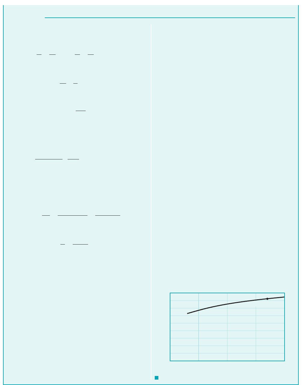
GIVEN Water at 1 see Table 1.52
is to flow from reservoir A to reservoir B through a pipe of
length 1700 ft and roughness 0.0005 ft at a rate of
as shown in Fig. E8.13a. The system contains a sharp-edged
entrance and four flanged elbows.
FIND Determine the pipe diameter needed.
45°
Q ⫽ 26 ft
3
Ⲑ
s
n ⫽ 1.21 ⫻ 10
⫺5
ft
2
Ⲑ
s,
60 °F
Type III with Minor Losses, Determine Diameter
E
XAMPLE 8.13
(2)
(1)
Elevation
z
2
= 0
Elevation
z
1
= 44 ft
Total length = 1700 ft
D
B
A
F I G U R E E8.13
a
JWCL068_ch08_383-460.qxd 9/23/08 10:58 AM Page 435
436 Chapter 8 ■ Viscous Flow in Pipes
S
OLUTION
ment. A few rounds of calculation will reveal that the solution is
given by
(Ans)
COMMENTS Alternatively, we can use the Colebrook equa-
tion rather than the Moody chart to solve for D. This is easily
done by using the Colebrook equation (Eq. 8.35a) with f as a
function of D obtained from Eq. 3 and Re and as functions of
D from Eqs. 4 and 5. The resulting single equation for D can be
solved by using a root-finding technique on a computer or calcu-
lator to obtain . This agrees with the solution ob-
tained using the Moody chart.
By repeating the calculations for various pipe lengths, ,
the results shown in Fig. E8.13b are obtained. As the pipe
length increases it is necessary, because of the increased fric-
tion, to increase the pipe diameter to maintain the same
flowrate.
It is interesting to attempt to solve this example if all losses are
neglected so that Eq. 1 becomes Clearly from Fig. E8.13a,
Obviously something is wrong. A fluid cannot flow
from one elevation, beginning with zero pressure and velocity,
and end up at a lower elevation with zero pressure and velocity
unless energy is removed 1i.e., a head loss or a turbine2some-
where between the two locations. If the pipe is short 1negligible
friction2and the minor losses are negligible, there is still the ki-
netic energy of the fluid as it leaves the pipe and enters the reser-
voir. After the fluid meanders around in the reservoir for some
time, this kinetic energy is lost and the fluid is stationary. No mat-
ter how small the viscosity is, the exit loss cannot be neglected.
The same result can be seen if the energy equation is written from
the free surface of the upstream tank to the exit plane of the pipe,
at which point the kinetic energy is still available to the fluid. In
either case the energy equation becomes in agree-
ment with the inviscid results of Chapter 3 1the Bernoulli
equation2.
z
1
⫽ V
2
Ⲑ
2g
z
1
⫽ 44 ft.
z
1
⫽ 0.
/
D ⫽ 1 .63 ft
e
Ⲑ
D
D ⬇ 1.63 ft
The energy equation 1Eq. 8.212can be applied between two points
on the surfaces of the reservoirs
as follows:
or
(1)
where or
(2)
is the velocity within the pipe. 1Note that the units on V and D are
and ft, respectively.2The loss coefficients are obtained from
Table 8.2 and Figs. 8.22 and 8.25 as
and Thus, Eq. 1 can be written as
or, when combined with Eq. 2 to eliminate V,
(3)
To determine D we must know f, which is a function of Re and
where
(4)
and
(5)
where D is in feet. Again, we have four equations 1Eqs. 3, 4, 5, and
the Moody chart or the Colebrook equation2for the four un-
knowns D, f, Re, and
Consider the solution by using the Moody chart. Although
it is often easiest to assume a value of f and make calculations
to determine if the assumed value is the correct one, with the
inclusion of minor losses this may not be the simplest method.
For example, if we assume and calculate D from
Eq. 3, we would have to solve a fifth-order equation. With
only major losses 1see Example 8.122, the term proportional to
D in Eq. 3 is absent, and it is easy to solve for D if f is given.
With both major and minor losses included, this solution
for D 1given f 2would require a trial-and-error or iterative
technique.
Thus, for this type of problem it is perhaps easier to assume
a value of D, calculate the corresponding f from Eq. 3, and with
the values of Re and determined from Eqs. 4 and 5, look up
the value of f in the Moody chart 1or the Colebrook equation2.
The solution is obtained when the two values of f are in agree-
e
Ⲑ
D
f ⫽ 0.02
e
Ⲑ
D.
e
D
⫽
0.0005
D
Re ⫽
VD
n
⫽
3133.12
Ⲑ
D
2
4D
1.21 ⫻ 10
⫺5
⫽
2.74 ⫻ 10
6
D
e
Ⲑ
D,
f ⫽ 0.00152 D
5
⫺ 0.00135 D
44 ft ⫽
V
2
2132.2 ft
Ⲑ
s
2
2
e
1700
D
f ⫹ 3410.22⫹ 0.5 ⫹ 14f
K
L
exit
⫽ 1.
K
L
elbow
⫽ 0.2,K
L
ent
⫽ 0.5,
ft
Ⲑ
s
V ⫽
33.1
D
2
V ⫽ Q
Ⲑ
A ⫽ 4Q
Ⲑ
pD
2
⫽ 4126 ft
3
Ⲑ
s2
Ⲑ
pD
2
,
z
1
⫽
V
2
2g
af
/
D
⫹
a
K
L
b
p
1
g
⫹
V
2
1
2g
⫹ z
1
⫽
p
2
g
⫹
V
2
2
2g
⫹ z
2
⫹ h
L
V
2
⫽ z
2
⫽ 021p
1
⫽ p
2
⫽ V
1
⫽
(1700 ft, 1.63 ft)
1.8
1.6
1.4
1.2
1.0
0.8
0.6
0.4
0.2
0.0
0 500 1000
ᐉ, ft
D, ft
1500 2000
F I G U R E E8.13
b
JWCL068_ch08_383-460.qxd 9/23/08 10:59 AM Page 436