Munson B.R. Fundamentals of Fluid Mechanics
Подождите немного. Документ загружается.

where D and f are based on the pipe containing the component. The head loss of the pipe system
is the same as that produced in a straight pipe whose length is equal to the pipes of the original
system plus the sum of the additional equivalent lengths of all of the components of the system.
Most pipe flow analyses, including those in this book, use the loss coefficient method rather than
the equivalent length method to determine the minor losses.
Many pipe systems contain various transition sections in which the pipe diameter changes
from one size to another. Such changes may occur abruptly or rather smoothly through some type
of area change section. Any change in flow area contributes losses that are not accounted for in
the fully developed head loss calculation 1the friction factor2. The extreme cases involve flow into
a pipe from a reservoir 1an entrance2or out of a pipe into a reservoir 1an exit2.
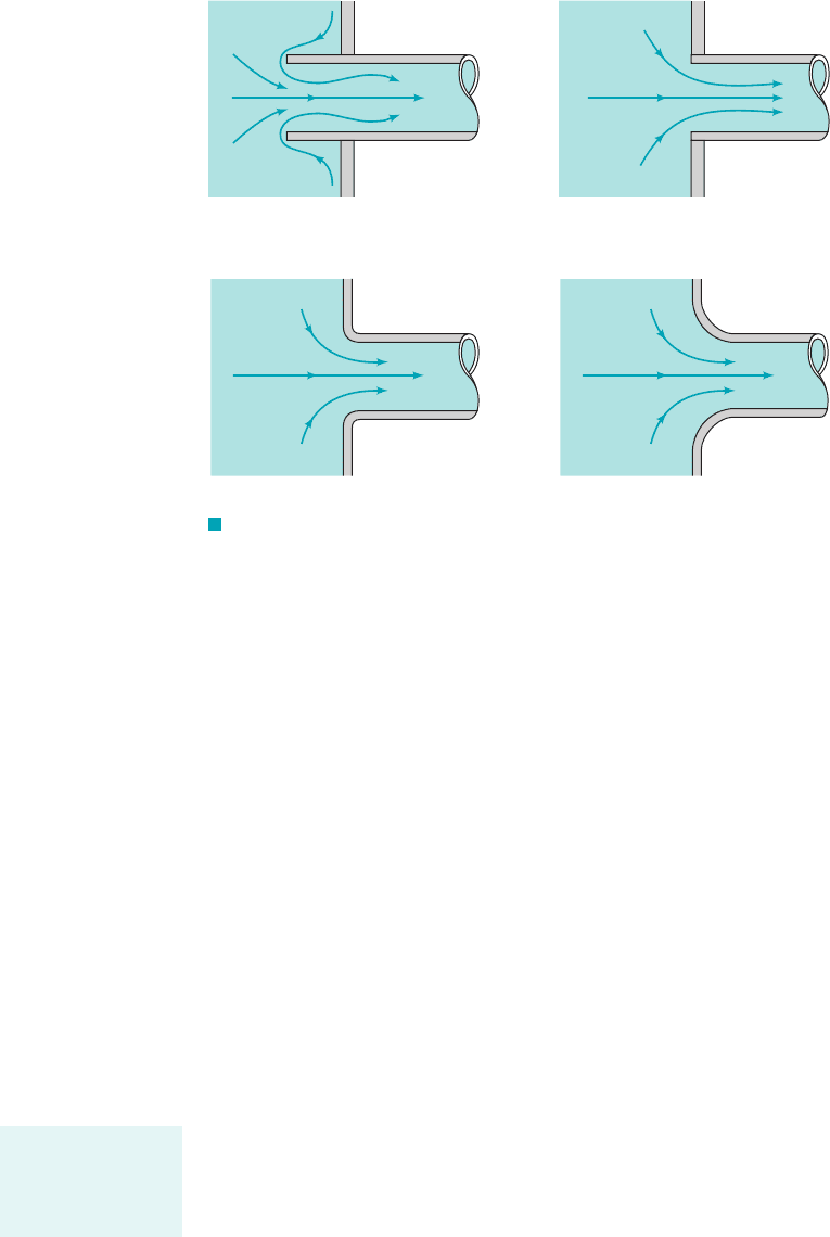
A fluid may flow from a reservoir into a pipe through any number of differently shaped en-
trance regions as are sketched in Fig. 8.22. Each geometry has an associated loss coefficient. A
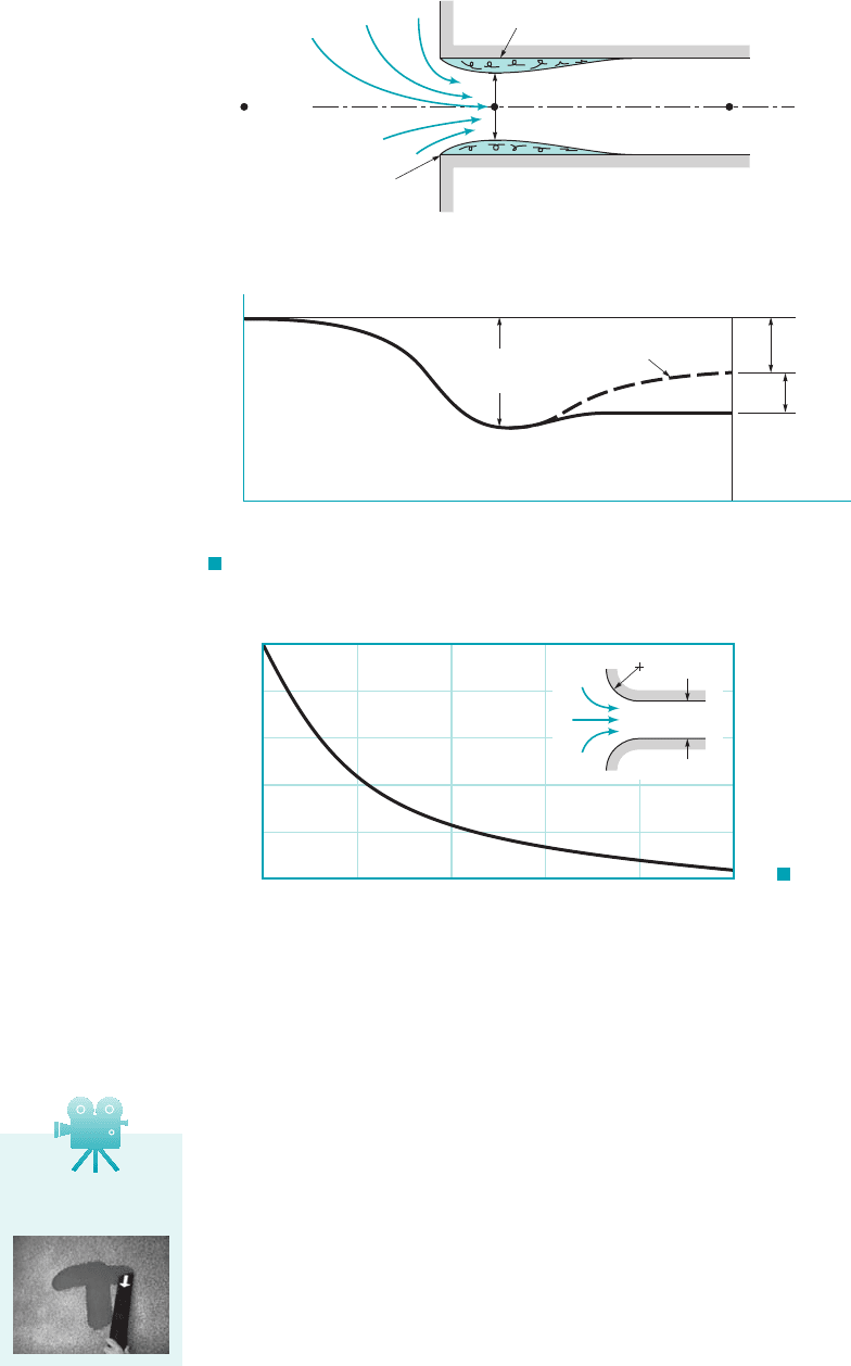
typical flow pattern for flow entering a pipe through a square-edged entrance is sketched in Fig.
8.23. As was discussed in Chapter 3, a vena contracta region may result because the fluid cannot
turn a sharp right-angle corner. The flow is said to separate from the sharp corner. The maximum
velocity at section 122is greater than that in the pipe at section 132, and the pressure there is lower.
If this high-speed fluid could slow down efficiently, the kinetic energy could be converted into
pressure 1the Bernoulli effect2, and the ideal pressure distribution indicated in Fig. 8.23 would re-
sult. The head loss for the entrance would be essentially zero.
Such is not the case. Although a fluid may be accelerated very efficiently, it is very difficult
to slow down 1decelerate2a fluid efficiently. Thus, the extra kinetic energy of the fluid at section
122is partially lost because of viscous dissipation, so that the pressure does not return to the ideal
value. An entrance head loss 1pressure drop2is produced as is indicated in Fig. 8.23. The majority
of this loss is due to inertia effects that are eventually dissipated by the shear stresses within the
fluid. Only a small portion of the loss is due to the wall shear stress within the entrance region.
The net effect is that the loss coefficient for a square-edged entrance is approximately
One-half of a velocity head is lost as the fluid enters the pipe. If the pipe protrudes into the tank
1a reentrant entrance2as is shown in Fig. 8.22a, the losses are even greater.
An obvious way to reduce the entrance loss is to round the entrance region as is shown in
Fig. 8.22c, thereby reducing or eliminating the vena contracta effect. Typical values for the loss
coefficient for entrances with various amounts of rounding of the lip are shown in Fig. 8.24. A sig-
nificant reduction in can be obtained with only slight rounding.K
L
K
L
⫽ 0.50.
8.4 Dimensional Analysis of Pipe Flow 417
(a)(b)
(
c)(d)
F I G U R E 8.22 Entrance flow conditions and loss coefficient
(Refs. 28, 29). (a) Reentrant, (b) sharp-edged, (c) slightly
rounded, (see Fig. 8.24), (d) well-rounded, (see Fig. 8.24).K
L
ⴝ 0.04K
L
ⴝ 0.2
K
L
ⴝ 0.5,K
L
ⴝ 0.8,
Minor head losses
are often a result of
the dissipation of
kinetic energy.
JWCL068_ch08_383-460.qxd 9/23/08 10:53 AM Page 417
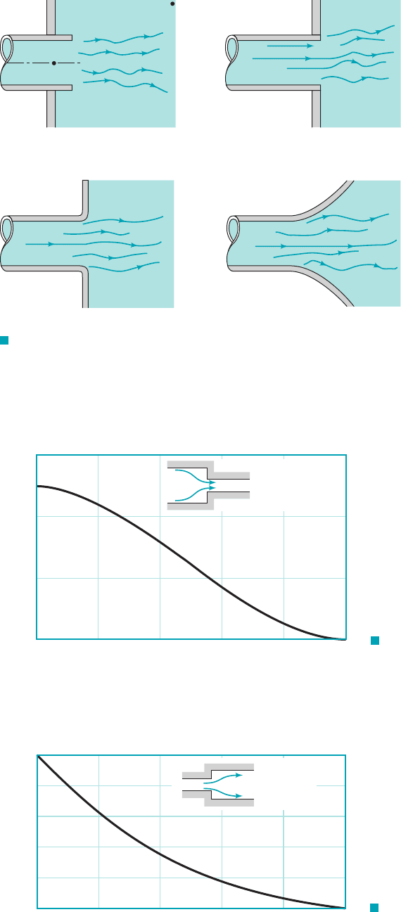
A head loss 1the exit loss2is also produced when a fluid flows from a pipe into a tank as is shown
in Fig. 8.25. In these cases the entire kinetic energy of the exiting fluid 1velocity 2is dissipated through
viscous effects as the stream of fluid mixes with the fluid in the tank and eventually comes to rest
The exit loss from points 112and 122is therefore equivalent to one velocity head, or
Losses also occur because of a change in pipe diameter as is shown in Figs. 8.26 and 8.27.
The sharp-edged entrance and exit flows discussed in the previous paragraphs are limiting cases
of this type of flow with either respectively. The loss coefficient for a
sudden contraction, is a function of the area ratio, as is shown in Fig.
8.26. The value of changes gradually from one extreme of a sharp-edged entrance
with to the other extreme of no area change with
In many ways, the flow in a sudden expansion is similar to exit flow. As is indicated in Fig.
8.28, the fluid leaves the smaller pipe and initially forms a jet-type structure as it enters the larger
pipe. Within a few diameters downstream of the expansion, the jet becomes dispersed across the
pipe, and fully developed flow becomes established again. In this process [between sections 122and
132] a portion of the kinetic energy of the fluid is dissipated as a result of viscous effects. A square-
edged exit is the limiting case with
A sudden expansion is one of the few components 1perhaps the only one2for which the loss
coefficient can be obtained by means of a simple analysis. To do this we consider the continuity
A
1
Ⲑ
A
2
⫽ 0.
K
L
⫽ 02.1A
2
Ⲑ
A
1
⫽ 1K
L
⫽ 0.502
1A
2
Ⲑ
A
1
⫽ 0K
L
A
2
Ⲑ
A
1
,K
L
⫽ h
L
Ⲑ
1V
2
2
Ⲑ
2g2,
A
1
Ⲑ
A
2
⫽
q
, or A
1
Ⲑ
A
2
⫽ 0,
K
L
⫽ 1.1V
2
⫽ 02.
V
1
418 Chapter 8 ■ Viscous Flow in Pipes
Vena contracta
(2)
(3)
(1)
V
2
> V
3
x
V
1
= 0
Flow separation
at corner
Separated flow
(
a)
p
1
p
3
x
1
x
2
x
3
x
p
(b)
Actual
Ideal full recovery
of kinetic energy
V
2
2
____
2
ρ
V
2
3
____
2
ρ
V
2
3
____
2
ρ
K
L
F I G U R E 8.23 Flow pattern and pressure distribution for a sharp-
edged entrance.
D
r
0.5
0.4
0.3
0.2
0.1
0
0 0.05 0.1 0.15 0.20 0.25
r
__
D
K
L
F I G U R E 8.24
Entrance loss coefficient as a
function of rounding of the
inlet edge (Ref. 9).
V8.10 Entrance/exit
flows
JWCL068_ch08_383-460.qxd 9/23/08 10:53 AM Page 418
8.4 Dimensional Analysis of Pipe Flow 419
(a)
(
c) (d)
(
b)
(1)
(2)
F I G U R E 8.25 Exit flow conditions and loss coefficient.
(a) Reentrant, (b) sharp-edged, (c) slightly rounded,
(d) well-rounded, K
L
ⴝ 1.0.
K
L
ⴝ 1.0,K
L
ⴝ 1.0,K
L
ⴝ 1.0,
A
1
A
2
h
L
=
K
L
V
2
2
___
2
g
0.6
0.4
0.2
0
0 0.2 0.4 0.6 0.8 1.0
A
2
/A
1
K
L
F I G U R E 8.26
Loss coefficient for a sudden
contraction (Ref. 10).
A
1
A
2
h
L
=
K
L
V
1
2
___
2
g
1.0
0.8
0.6
0.4
0.2
0
0 0.2 0.4 0.6 0.8 1.0
A
1
/A
2
K
L
F I G U R E 8.27
Loss coefficient for a sudden
expansion (Ref. 10).
JWCL068_ch08_383-460.qxd 9/23/08 10:53 AM Page 419
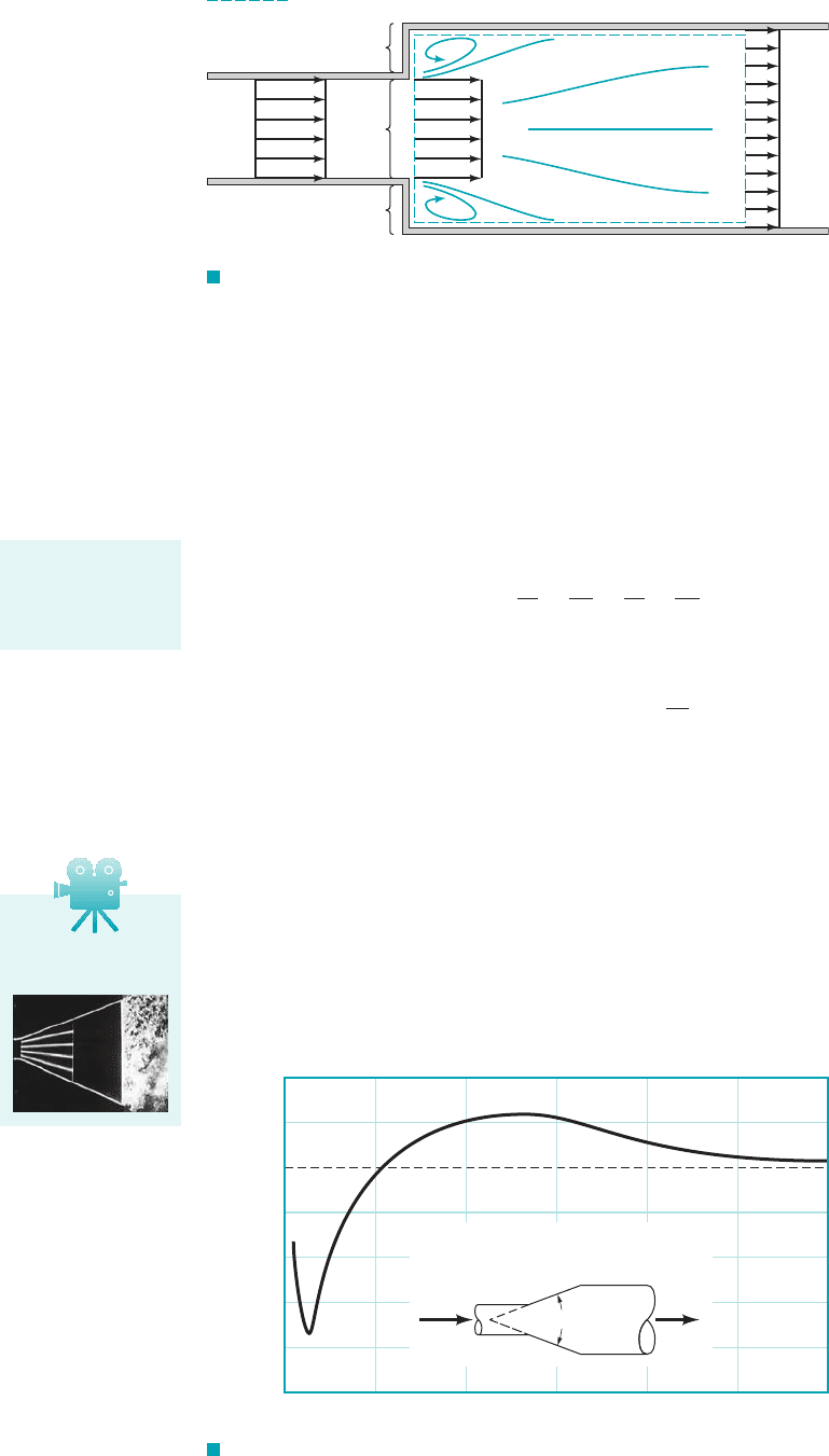
and momentum equations for the control volume shown in Fig. 8.28 and the energy equation ap-
plied between 122and 132. We assume that the flow is uniform at sections 112, 122, and 132and the
pressure is constant across the left-hand side of the control volume The re-
sulting three governing equations 1mass, momentum, and energy2are
and
These can be rearranged to give the loss coefficient, as
where we have used the fact that This result, plotted in Fig. 8.27, is in good agreement
with experimental data. As with so many minor loss situations, it is not the viscous effects directly
1i.e., the wall shear stress2that cause the loss. Rather, it is the dissipation of kinetic energy 1another
type of viscous effect2as the fluid decelerates inefficiently.
The losses may be quite different if the contraction or expansion is gradual. Typical re-
sults for a conical diffuser with a given area ratio, are shown in Fig. 8.29. 1A diffuser
is a device shaped to decelerate a fluid.2Clearly the included angle of the diffuser, is a very
important parameter. For very small angles, the diffuser is excessively long and most of the head
loss is due to the wall shear stress as in fully developed flow. For moderate or large angles, the flow
separates from the walls and the losses are due mainly to a dissipation of the kinetic energy of the jet
leaving the smaller diameter pipe. In fact, for moderate or large values of 1i.e., for the caseu 7 35°u
u,
A
2
Ⲑ
A
1
,
A
2
⫽ A
3
.
K
L
⫽ a1 ⫺
A
1
A
2
b
2
K
L
⫽ h
L
Ⲑ
1V
2
1
Ⲑ
2g2,
p
1
g
⫹
V
2
1
2g
⫽
p
3
g
⫹
V
2
3
2g
⫹ h
L
p
1
A
3
⫺ p
3
A
3
⫽ rA
3
V
3
1V
3
⫺ V
1
2
A
1
V
1
⫽ A
3
V
3
1p
a
⫽ p
b
⫽ p
c
⫽ p
1
2.
420 Chapter 8 ■ Viscous Flow in Pipes
(2) (3)
(1)
V
1
V
1
V
3
b
c
a
Control volume
F I G U R E 8.28 Control volume used to calculate the loss coefficient
for a sudden expansion.
The loss coefficient
for a sudden expan-
sion can be theoret-
ically calculated.
F I G U R E 8.29 Loss coefficient for a typical conical diffuser (Ref. 5).
1.4
1.2
1.0
0.8
0.6
0.4
0.2
0
0 30 60 90
, degrees
θ
θ
120 150 180
V
1
V
2
h
L
= K
L
fixed
V
2
1
___
2g
K
L
____________
(1
–
A
1
/A
2
)
2
A
2
___
A
1
V8.11 Separated
flow in a diffuser
JWCL068_ch08_383-460.qxd 9/23/08 10:53 AM Page 420
8.4 Dimensional Analysis of Pipe Flow 421
V8.12 Car exhaust
system
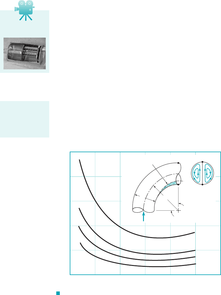
F I G U R E 8.30 Character of the flow in a bend and the
associated loss coefficient (Ref. 5).
90ⴗ
Separated flow
bb
a
Secondary
flow
90°
Primary
flow
D
a
__
D
= 0.01
0.002
0.001
0
1.0
0.8
0.6
0.4
0.2
0
024681012
/D
K
L
∋
shown in Fig. 8.292, the conical diffuser is, perhaps unexpectedly, less efficient than a sharp-edged ex-
pansion which has There is an optimum angle 1 for the case illustrated2for
which the loss coefficient is a minimum. The relatively small value of for the minimum results
in a long diffuser and is an indication of the fact that it is difficult to efficiently decelerate a fluid.
It must be noted that the conditions indicated in Fig. 8.29 represent typical results only. Flow
through a diffuser is very complicated and may be strongly dependent on the area ratio spe-
cific details of the geometry, and the Reynolds number. The data are often presented in terms of a
pressure recovery coefficient, which is the ratio of the static pressure rise
across the diffuser to the inlet dynamic pressure. Considerable effort has gone into understanding
this important topic 1Refs. 11, 122.
Flow in a conical contraction 1a nozzle; reverse the flow direction shown in Fig. 8.292is
less complex than that in a conical expansion. Typical loss coefficients based on the downstream
1high-speed2velocity can be quite small, ranging from for to for
for example. It is relatively easy to accelerate a fluid efficiently.
Bends in pipes produce a greater head loss than if the pipe were straight. The losses are due
to the separated region of flow near the inside of the bend 1especially if the bend is sharp2and the
swirling secondary flow that occurs because of the imbalance of centripetal forces as a result of
the curvature of the pipe centerline. These effects and the associated values of for large Reynolds
number flows through a bend are shown in Fig. 8.30. The friction loss due to the axial length
of the pipe bend must be calculated and added to that given by the loss coefficient of Fig. 8.30.
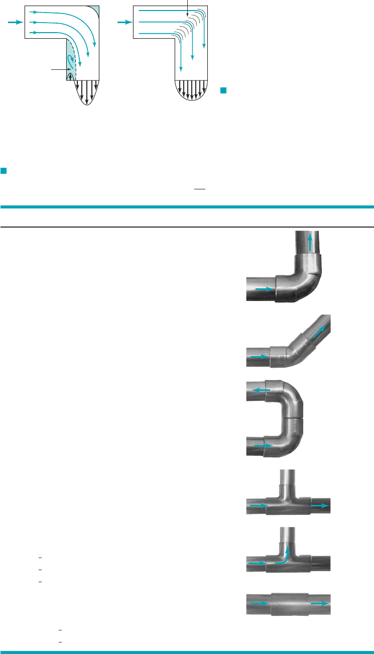
For situations in which space is limited, a flow direction change is often accomplished by
use of miter bends, as is shown in Fig. 8.31, rather than smooth bends. The considerable losses in
such bends can be reduced by the use of carefully designed guide vanes that help direct the flow
with less unwanted swirl and disturbances.
Another important category of pipe system components is that of commercially available
pipe fittings such as elbows, tees, reducers, valves, and filters. The values of for such compo-
nents depend strongly on the shape of the component and only very weakly on the Reynolds num-
ber for typical large Re flows. Thus, the loss coefficient for a elbow depends on whether the
pipe joints are threaded or flanged but is, within the accuracy of the data, fairly independent of the
pipe diameter, flow rate, or fluid properties 1the Reynolds number effect2. Typical values of for
such components are given in Table 8.2. These typical components are designed more for ease of
manufacturing and costs than for reduction of the head losses that they produce. The flowrate from
a faucet in a typical house is sufficient whether the value of for an elbow is the typical
or it is reduced to by use of a more expensive long-radius, gradual bend 1Fig. 8.302.K
L
⫽ 0.2
K
L
⫽ 1.5,K
L
K
L
90°
K
L
90°
K
L
u ⫽ 60°,
K
L
⫽ 0.07u ⫽ 30°,K
L
⫽ 0.02
C
p
⫽ 1p
2
⫺ p
1
2
Ⲑ
1rV
2
1
Ⲑ
22,
A
2
Ⲑ
A
1
,
K
L
u
u ⬇ 8°K
L
⫽ 11 ⫺ A
1
Ⲑ
A
2
2
2
.
Extensive tables are
available for loss
coefficients of stan-
dard pipe compo-
nents.
JWCL068_ch08_383-460.qxd 9/23/08 10:54 AM Page 421
422 Chapter 8 ■ Viscous Flow in Pipes
K
L
≈ 1.1
Q
Separated
flow
K
L
≈ 0.2
Guide vanes
Q
(a) (b)
F I G U R E 8.31 Character
of the flow in a mitered bend and the
associated loss coefficient: (a) without
guide vanes, (b) with guide vanes.
90ⴗ
TABLE 8.2
Loss Coefficients for Pipe Components (Data from Refs. 5, 10, 27)
Component
a. Elbows
Regular flanged 0.3
Regular threaded 1.5
Long radius flanged 0.2
Long radius threaded 0.7
Long radius flanged 0.2
Regular threaded 0.4
b. return bends
return bend, flanged 0.2
return bend, threaded 1.5
c. Tees
Line flow, flanged 0.2
Line flow, threaded 0.9
Branch flow, flanged 1.0
Branch flow, threaded 2.0
d. Union, threaded 0.08
*
e. Valves
Globe, fully open 10
Angle, fully open 2
Gate, fully open 0.15
Gate, closed 0.26
Gate, closed 2.1
Gate, closed 17
Swing check, forward flow 2
Swing check, backward flow
Ball valve, fully open 0.05
Ball valve, closed 5.5
Ball valve, closed 210
*
See Fig. 8.32 for typical valve geometry.
2
3
1
3
3
4
1
2
1
4
180°
180°
180ⴗ
45°,
45°,
90°,
90°,
90°,
90°,
K
L
ah
L
ⴝ K
L
V
2
2g
b
V
V
V
V
V
V
JWCL068_ch08_383-460.qxd 9/23/08 10:54 AM Page 422
8.4 Dimensional Analysis of Pipe Flow 423
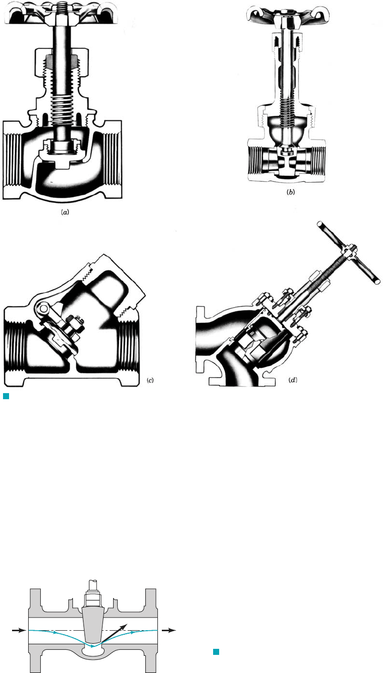
F I G U R E 8.32 Internal structure of various valves: (a) globe valve, (b) gate valve,
(c) swing check valve, (d) stop check valve. (Courtesy of Crane Co., Valve Division.)
F I G U R E 8.33 Head loss in a valve
is due to dissipation of the kinetic energy of the
large-velocity fluid near the valve seat.
V
3
>> V
1
V
1
V
2
= V
1
(1) (2)
Valves control the flowrate by providing a means to adjust the overall system loss coefficient
to the desired value. When the valve is closed, the value of is infinite and no fluid flows. Open-
ing of the valve reduces producing the desired flowrate. Typical cross sections of various types
of valves are shown in Fig. 8.32. Some valves 1such as the conventional globe valve2are designed
for general use, providing convenient control between the extremes of fully closed and fully open.
Others 1such as a needle valve2are designed to provide very fine control of the flowrate. The check
valve provides a diode type operation that allows fluid to flow in one direction only.
Loss coefficients for typical valves are given in Table 8.2. As with many system components,
the head loss in valves is mainly a result of the dissipation of kinetic energy of a high-speed por-
tion of the flow. This high speed, is illustrated in Fig. 8.33.V
3
,
K
L
,
K
L
JWCL068_ch08_383-460.qxd 9/23/08 10:54 AM Page 423
424 Chapter 8 ■ Viscous Flow in Pipes
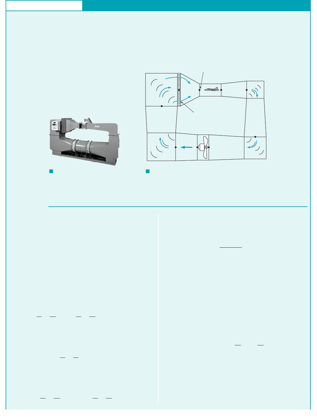
GIVEN The closed-circuit wind tunnel shown in Fig. E8.6a is a
smaller version of that depicted in Fig. E8.6b in which air at stan-
dard conditions is to flow through the test section [between sections
(5) and (6)] with a velocity of 200 ft/s. The flow is driven by a fan
that essentially increases the static pressure by the amount p
1
⫺ p
9
that is needed to overcome the head losses experienced by the fluid
as it flows around the circuit.
FIND Estimate the value of and the horsepower sup-
plied to the fluid by the fan.
p
1
⫺ p
9
S
OLUTION
Minor Losses
where is the actual head rise supplied by the pump 1fan2to the
air. Again since and this, when combined with
Eq. 1, becomes
The actual power supplied to the air 1horsepower, 2is obtained
from the fan head by
(2)
Thus, the power that the fan must supply to the air depends on
the head loss associated with the flow through the wind tunnel. To
obtain a reasonable, approximate answer we make the following
assumptions. We treat each of the four turning corners as a mitered
bend with guide vanes so that from Fig. 8.31 Thus,
for each corner
where, because the flow is assumed incompressible,
The values of A and the corresponding velocities throughout the
tunnel are given in Table E8.6.
We also treat the enlarging sections from the end of the test
section 162to the beginning of the nozzle 142as a conical diffuser
with a loss coefficient of This value is larger than that
of a well-designed diffuser 1see Fig. 8.29, for example2. Since the
K
L
dif
⫽ 0.6.
V ⫽ V
5
A
5
Ⲑ
A.
h
L
corner
⫽ K
L
V
2
2g
⫽ 0.2
V
2
2g
K
L
corner
⫽ 0.2.
p
a
⫽ gQh
p
⫽ gA
5
V
5
h
p
⫽ gA
5
V
5
h
L
1⫺9
p
a
h
p
⫽
1p
1
⫺ p
9
2
g
⫽ h
L
1⫺9
V
9
⫽ V
1
z
9
⫽ z
1
h
p
E
XAMPLE 8.6
The maximum velocity within the wind tunnel occurs in the
test section 1smallest area; see Table E8.6 on the next page2.
Thus, the maximum Mach number of the flow is
where and from Eq. 1.20 the speed of sound is
Thus, As was indicated in
Chapter 3 and discussed fully in Chapter 11, most flows can be con-
sidered as incompressible if the Mach number is less than about 0.3.
Hence, we can use the incompressible formulas for this problem.
The purpose of the fan in the wind tunnel is to provide the nec-
essary energy to overcome the net head loss experienced by the
air as it flows around the circuit. This can be found from the en-
ergy equation between points 112and 192as
where is the total head loss from 112to 192. With and
this gives
(1)
Similarly, by writing the energy equation 1Eq. 5.842across the fan,
from 192to 112, we obtain
p
9
g
⫹
V
2
9
2g
⫹ z
9
⫹ h
p
⫽
p
1
g
⫹
V
2
1
2g
⫹ z
1
p
1
g
⫺
p
9
g
⫽ h
L
1⫺9
V
1
⫽ V
9
z
1
⫽ z
9
h
L
1⫺9
p
1
g
⫹
V
2
1
2g
⫹ z
1
⫽
p
9
g
⫹
V
2
9
2g
⫹ z
9
⫹ h
L
1⫺9
0.179.200
Ⲑ
1117 ⫽Ma
5
⫽1117 ft
Ⲑ
s.
31460⫹ 592°R46
1
Ⲑ
2
⫽11716 ft
#
lb
Ⲑ
slug
#
°R2c
5
⫽1kRT
5
2
1
Ⲑ
2
⫽ 51.4
V
5
⫽ 200 ft
Ⲑ
s
Ma
5
⫽ V
5
Ⲑ
c
5
,
(4)
V
5
= 200 ft/s
(5)
(6)
(7)
(8)
Fan
Q
(1)
(9)
(2)
Test section
Flow-straightening
screens
(3)
F I G U R E E8.6
b
F I G U R E E8.6
a
(Photograph courtesy of
DELTALAB.France.)
JWCL068_ch08_383-460.qxd 9/23/08 10:54 AM Page 424
8.4.3 Noncircular Conduits
Many of the conduits that are used for conveying fluids are not circular in cross section. Although the
details of the flows in such conduits depend on the exact cross-sectional shape, many round pipe re-
sults can be carried over, with slight modification, to flow in conduits of other shapes.
Theoretical results can be obtained for fully developed laminar flow in noncircular
ducts, although the detailed mathematics often becomes rather cumbersome. For an arbitrary
8.4 Dimensional Analysis of Pipe Flow 425
wind tunnel diffuser is interrupted by the four turning corners and
the fan, it may not be possible to obtain a smaller value of for
this situation. Thus,
The loss coefficients for the conical nozzle between section 142
and 152and the flow-straightening screens are assumed to be
and 1Ref. 132, respectively. We neglect the
head loss in the relatively short test section.
Thus, the total head loss is
or
or
Hence, from Eq. 1 we obtain the pressure rise across the fan as
(Ans)
From Eq. 2 we obtain the power added to the fluid as
or
(Ans)
p
a
⫽
34,300 ft
#
lb
Ⲑ
s
550 1ft
#
lb
Ⲑ
s2
Ⲑ
hp
⫽ 62.3 hp
⫽ 34,300 ft
#
lb
Ⲑ
s
p
a
⫽ 10.0765 lb
Ⲑ
ft
3
214.0 ft
2
21200 ft
Ⲑ
s21560 ft2
⫽ 42.8 lb
Ⲑ
ft
2
⫽ 0.298 psi
p
1
⫺ p
9
⫽ gh
L
1⫺9
⫽ 10.0765 lb
Ⲑ
ft
3
21560 ft2
h
L
1⫺9
⫽ 560 ft
⫹ 0.212002
2
⫹ 4.0122.92
2
4 ft
2
Ⲑ
s
2
Ⲑ
32132.2 ft
Ⲑ
s
2
24
⫽ 30.2180.0
2
⫹ 44.4
2
⫹ 28.6
2
⫹ 22.9
2
2⫹ 0.612002
2
⫹ 0.6V
2
6
⫹ 0.2V
2
5
⫹ 4.0V
2
4
4
Ⲑ
2g
h
L
1⫺9
⫽ 30.21V
2
7
⫹ V
2
8
⫹ V
2
2
⫹ V
2
3
2
⫹ h
L
dif
⫹ h
L
noz
⫹ h
L
scr
h
L
1⫺9
⫽ h
L
corner7
⫹ h
L
corner8
⫹ h
L
corner2
⫹ h
L
corner3
K
L
scr
⫽ 4.0K
L
noz
⫽ 0.2
h
L
dif
⫽ K
L
dif
V
2
6
2g
⫽ 0.6
V
2
6
2g
K
L
dif
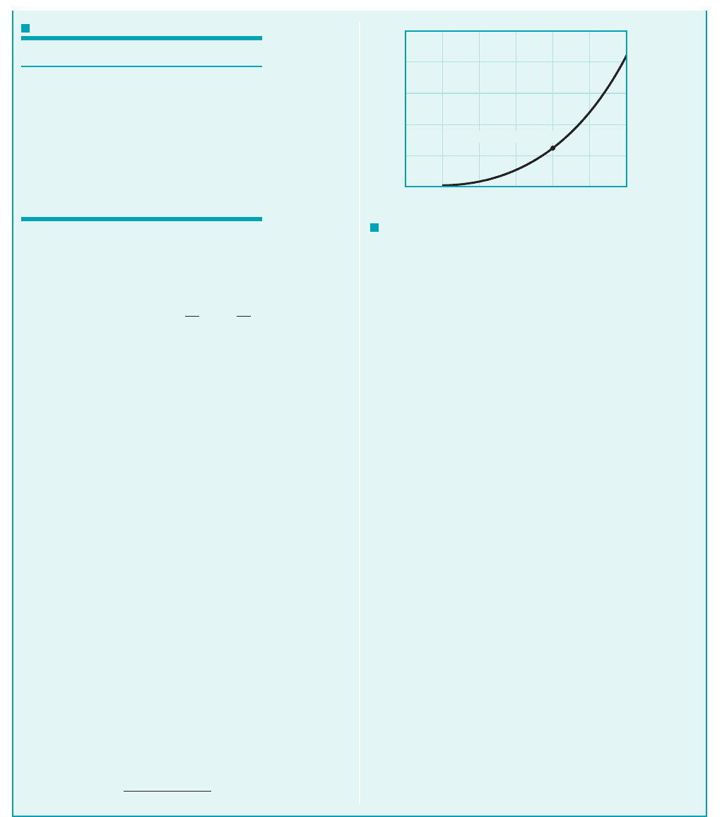
COMMENTS By repeating the calculations with various test
section velocities, , the results shown in Fig. E8.6c are ob-
tained. Since the head loss varies as and the power varies as
head loss times , it follows that the power varies as the cube of
the velocity. Thus, doubling the wind tunnel speed requires an
eightfold increase in power.
With a closed-return wind tunnel of this type, all of the
power required to maintain the flow is dissipated through vis-
cous effects, with the energy remaining within the closed tun-
nel. If heat transfer across the tunnel walls is negligible, the air
temperature within the tunnel will increase in time. For steady-
state operations of such tunnels, it is often necessary to provide
some means of cooling to maintain the temperature at accept-
able levels.
It should be noted that the actual size of the motor that powers
the fan must be greater than the calculated 62.3 hp because the fan
is not 100% efficient. The power calculated above is that needed
by the fluid to overcome losses in the tunnel, excluding those in
the fan. If the fan were 60% efficient, it would require a shaft
power of to run the fan. Determi-
nation of fan 1or pump2efficiencies can be a complex problem that
depends on the specific geometry of the fan. Introductory mater-
ial about fan performance is presented in Chapter 12; additional
material can be found in various references 1Refs. 14, 15, 16, for
example2.
It should also be noted that the above results are only
approximate. Clever, careful design of the various components
1corners, diffuser, etc.2may lead to improved 1i.e., lower2
values of the various loss coefficients, and hence lower power re-
quirements. Since is proportional to the components with
the larger V tend to have the larger head loss. Thus, even though
for each of the four corners, the head loss for corner 172
is times greater than it is for cor-
ner 132.
1V
7
Ⲑ
V
3
2
2
⫽ 180
Ⲑ
22.92
2
⫽ 12.2
K
L
⫽ 0.2
V
2
,
h
L
p ⫽ 62.3 hp
Ⲑ
10.602⫽ 104 hp
V
5
V
5
2
V
5
TABLE E8.6
Location Area ( ) Velocity ( )
1 22.0 36.4
2 28.0 28.6
3 35.0 22.9
4 35.0 22.9
5 4.0 200.0
6 4.0 200.0
7 10.0 80.0
8 18.0 44.4
9 22.0 36.4
ft
Ⲑ
sft
2
(200 ft/s, 62.3 hp)
250
200
150
100
50
0
0 50 100 150
V
5
, ft/s
ᏼ
a
, hp
200 250 300
F I G U R E E8.6
c
JWCL068_ch08_383-460.qxd 9/23/08 10:54 AM Page 425
cross section, as is shown in Fig. 8.34, the velocity profile is a function of both y and z
This means that the governing equation from which the velocity profile is obtained
1either the Navier–Stokes equations of motion or a force balance equation similar to that used for
circular pipes, Eq. 8.62is a partial differential equation rather than an ordinary differential equa-
tion. Although the equation is linear 1for fully developed flow the convective acceleration is zero2,
its solution is not as straightforward as for round pipes. Typically the velocity profile is given in
terms of an infinite series representation 1Ref. 172.
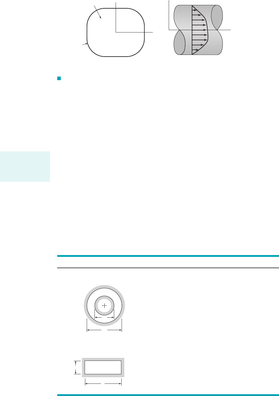
Practical, easy-to-use results can be obtained as follows. Regardless of the cross-sectional
shape, there are no inertia effects in fully developed laminar pipe flow. Thus, the friction fac-
tor can be written as where the constant C depends on the particular shape of the
duct, and is the Reynolds number, based on the hydraulic diameter. The
hydraulic diameter defined as is four times the ratio of the cross-sectional flow area
divided by the wetted perimeter, P, of the pipe as is illustrated in Fig. 8.34. It represents a char-
acteristic length that defines the size of a cross section of a specified shape. The factor of 4 is
included in the definition of so that for round pipes the diameter and hydraulic diameter are
equal The hydraulic diameter is also used in the definition
of the friction factor, and the relative roughness,
The values of for laminar flow have been obtained from theory and or experiment
for various shapes. Typical values are given in Table 8.3 along with the hydraulic diameter. Note
Ⲑ
C ⫽ f Re
h
e
Ⲑ
D
h
.h
L
⫽ f 1/
Ⲑ
D
h
2V
2
Ⲑ
2g,
3D
h
⫽ 4A
Ⲑ
P ⫽ 41pD
2
Ⲑ
42
Ⲑ
1pD2⫽ D4.
D
h
D
h
⫽ 4A
Ⲑ
P
Re
h
⫽ rVD
h
Ⲑ
m,Re
h
f ⫽ C
Ⲑ
Re
h
,
3V ⫽ u1y, z2i
ˆ
4.
426 Chapter 8 ■ Viscous Flow in Pipes
A = cross-sectional
area
P = perimeter
of pipe
D
h
= 4A/P = hydraulic
diameter
(
a)(b)
y
z
x
z
V
= u(y,z)
F I G U R E 8.34 Noncircular duct.
The hydraulic di-
ameter is used for
noncircular duct
calculations.
■ TABLE 8.3
Friction Factors for Laminar Flow in Noncircular Ducts (Data from Ref. 18)
Shape Parameter
0.0001 71.8
0.01 80.1
0.1 89.4
0.6 95.6
1.00 96.0
a兾b
0 96.0
0.05 89.9
0.10 84.7
0.25 72.9
0.50 62.2
0.75 57.9
1.00 56.9
D
1
Ⲑ
D
2
C ⴝ f Re
h
D
1
D
2
Concentric AnnulusI.
D
h
= D
2
– D
1
a
b
D
h
=
2
ab
_____
a + b
RectangleII.
JWCL068_ch08_383-460.qxd 9/23/08 10:54 AM Page 426