Short T.A. Electric Power Distribution Handbook
Подождите немного. Документ загружается.

Short-Circuit Protection 387
Like a circuit breaker, interruption occurs at a natural current zero. The
interrupting medium of a recloser is most commonly vacuum or oil. The
insulating medium is generally oil, air, a solid dielectric, or SF
6
. The recloser
control can be electronic, electromechanical (the relay for tripping is electro-
mechanical, and the reclosing control is electronic) or hydraulic. A hydraulic
recloser uses springs and hydraulic systems for timing and actuation.
The interrupting rating of a recloser is based on a symmetrical current
rating. The interrupting current rating does not change with voltage. There
is an exception that some reclosers have a higher interrupting current if
operated at a significantly lower voltage than the rating. Smaller reclosers
with a 50- to 200-A continuous rating typically have interrupting ratings
of 2 to 5 kA (these would normally be feeder reclosers). Larger reclosers
that could be used in substations have continuous current ratings as high
as 1120 A and interrupting ratings of 6 to 16 kA. Historically, reclosers with
series coil types had coil ratings of 25, 35, 50, 70, 100, 140, 200, 280, 400,
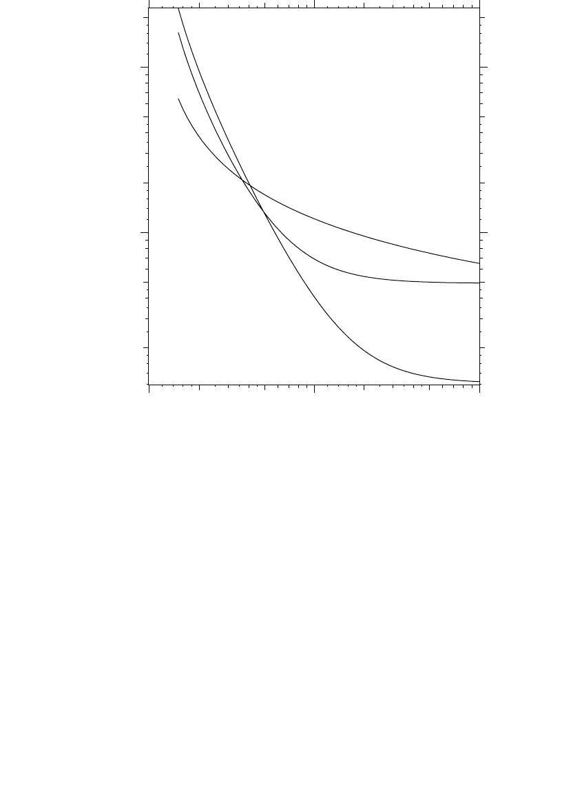
FIGURE 8.2
Relay curves following the IEEE standardized characteristics for a time dial = 5.
Moderately inverse
Very inverse
Extremely inverse
1.0 10.0 100.02. 20.5. 50.
1.0
10.0
0.2
2.
20.
0.5
5.
Current in multiples of the relay pickup
Time, seconds
1791_book.fm Page 387 Monday, August 4, 2003 3:20 PM
(C) 2004 by CRC Press LLC

388 Electric Power Distribution Handbook
and 560 A (each rating is approximately 1.4 times higher than the next
lower rating).
Reclosers are tested at a specified X/R ratio as specified in ANSI/IEEE
C37.60-1981. A typical test value is X/R = 16. While a lower X/R ratio at the
point of application does not mean you can increase the rating of a recloser,
the recloser must be derated if the X/R ratio is larger than that specified.
There are some other differences with recloser ratings vs. circuit breaker
ratings (Cooper Power Systems, 1994). Reclosers do not have to be derated
for multiple operations. Reclosers do not have a separate closing and latching
(or first-cycle) rating. The symmetrical current rating is sufficient to handle
the asymmetry during the first cycle as long as the circuit X/R ratio is lower
than the tested value.
Reclosers have many distribution applications. We find reclosers in the
substation as feeder interrupters instead of circuit breakers. An IEEE survey
found that 51% of station feeder interrupting devices were reclosers (IEEE
Working Group on Distribution Protection, 1995). Reclosers are used more
in smaller stations and circuit breakers more in larger stations. Three-phase
reclosers can be used on the main feeder to provide necessary protection
coverage on longer circuits, along with improved reliability. Overhead units
and padmounted units are available. Reclosers are available as single-phase
units, so they can be used on single-phase taps instead of fuses. Another
common application is in autoloop automation schemes to automatically
sectionalize customers after a fault.
Since reclosers are devices built for distribution circuits, some have features
that are targeted to distribution circuit needs. Three-phase units are available
that can operate each phase independently (so a single-phase fault will only
open one phase). Some reclosers have a feature called sequence coordination
to enhance coordination between multiple devices.
The time-current characteristics of hydraulic reclosers have letter designa-
tions: A, B, and C. The A is a fast curve that is used similarly to an instan-
taneous relay element, and the B and C curves have extra delay (“delayed”
and “extra delayed”). For a hydraulically-controlled recloser, the minimum
trip threshold is twice the full-load rating of the trip coil of the recloser and
is normally not adjustable. On electronically-controlled reclosers, the mini-
mum trip threshold is adjustable independently of the rating (analogous to
setting the pickup of a time-overcurrent relay).
8.2.5 Expulsion Fuses
Expulsion fuses are the most common protective device on distribution
circuits. Fuses are low-cost interrupters that are easily replaced (when in
cutouts). Interruption is relatively fast and can occur in a half of a cycle for
large currents. An expulsion fuse is a simple concept: a fusible element made
of tin or silver melts under high current. Expulsion fuses are most often
applied in a fuse cutout. In a fuse tube, after the fuse element melts, an arc
1791_book.fm Page 388 Monday, August 4, 2003 3:20 PM
(C) 2004 by CRC Press LLC
Short-Circuit Protection 389
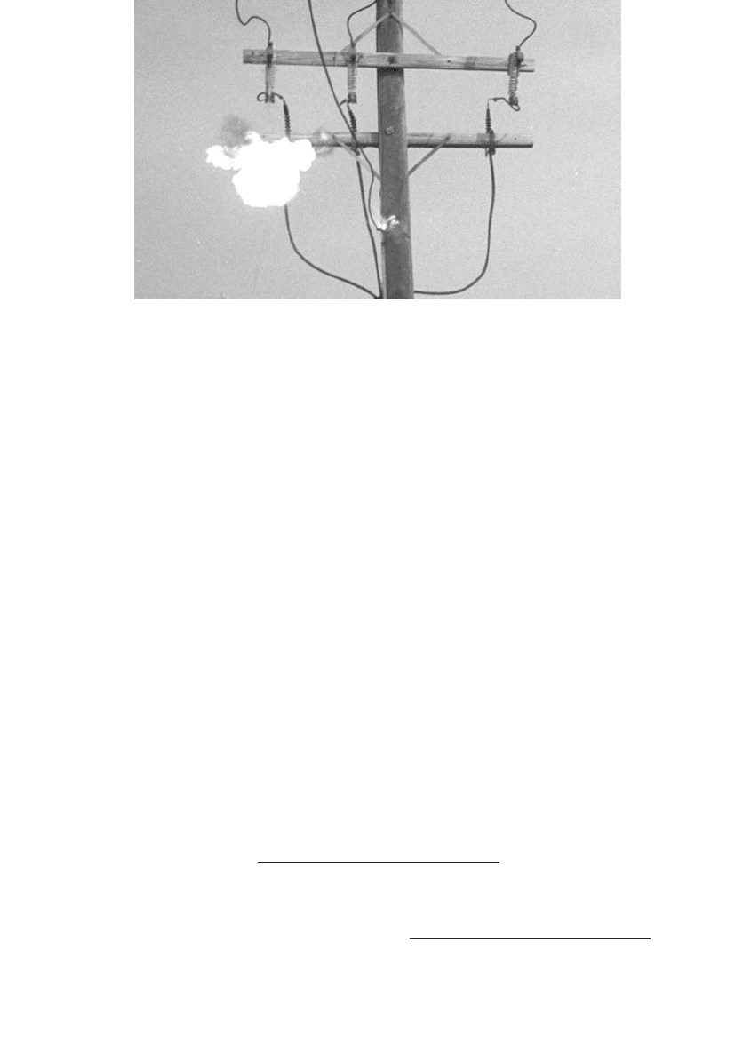
remains. The arc, which has considerable energy, causes a rapid pressure
buildup. This forces much of the ionized gas out of the bottom of the cutout
(see Figure 8.3), which helps to prevent the arc from reigniting at a current
zero. The extreme pressure, the stretching of the arc, and the turbulence help
increase the dielectric strength of the air and clear the arc at a current zero.
A fuse tube also has an organic fiber liner that melts under the heat of the
arc and emits fresh, non-ionized gases. At high currents, the expulsion action
predominates, while at lower currents, the deionizing gases increase the
dielectric strength the most.
The “expulsion” characteristics should be considered by crews when plac-
ing a cutout on a structure. Avoid placement where a blast of hot; ionized
gas blown out the bottom of the cutout could cause a flashover on another
phase or other energized equipment. Implement and enforce safety proce-
dures whenever a cutout is switched in (because it could be switching into
a fault), including eye protection, arc resistant clothing, and, of course, avoid-
ing the bottom of the cutout.
The speed ratio of a fuse quantifies how steep the fuse curve is. The speed
ratio is defined differently depending on the size of the fuse (IEEE Std.
C37.40-1993):
Speed ratio for fuse ratings of 100 A and under =
Speed ratio for ratings above 100 A =
FIGURE 8.3
Example operation of an expulsion fuse during a fault. (Courtesy of the Long Island Power
Authority.)
melting current at 0.1 seconds
melting current at 300 seconds
melting current at 0.1 seconds
melting current at 600 seconds
1791_book.fm Page 389 Monday, August 4, 2003 3:20 PM
(C) 2004 by CRC Press LLC

390 Electric Power Distribution Handbook
Industry standards specify two types of expulsion fuses, the most com-
monly used fuses. The “K” link is a relatively fast fuse, and the “T” is
somewhat slower. K links have a speed ratio of 6 to 8. T links have a speed
ratio of 10 to 13. The K link is the most commonly used fuse for transformers
and for line taps. The K and T fuse links are standardized well enough that
they are interchangeable among manufacturers for most applications.
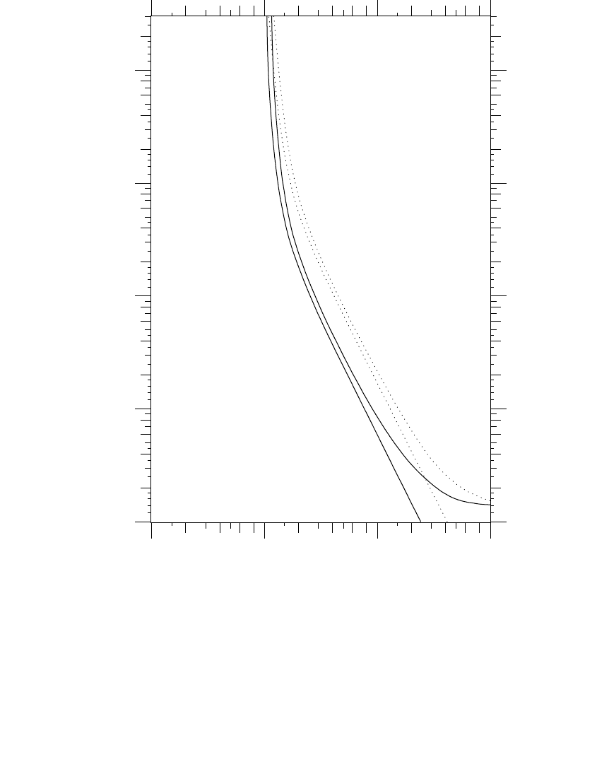
Two time-current curves are published for expulsion fuses: the minimum
melt curve and the maximum total clear curve. The minimum-melt time is
90% of the average melt time to account for manufacturing tolerances. The
total clearing time is the average melting time plus the arcing time plus
manufacturing tolerances. Figure 8.4 shows the two published curves for 50-
A K and T fuse links. The manufacturer’s minimum melt curves for fuses
less than or equal to 100 A normally start at 300 sec, and those over 100 A
start at 600 sec.
The time-current characteristics for K and T links are standardized at three
points (ANSI C37.42-1989). The minimum and maximum allowed melting
current is specified for durations of 0.1 sec, 10 sec, and either 300 sec (for
fuses rated 100 A or less) or 600 sec (for larger fuses).
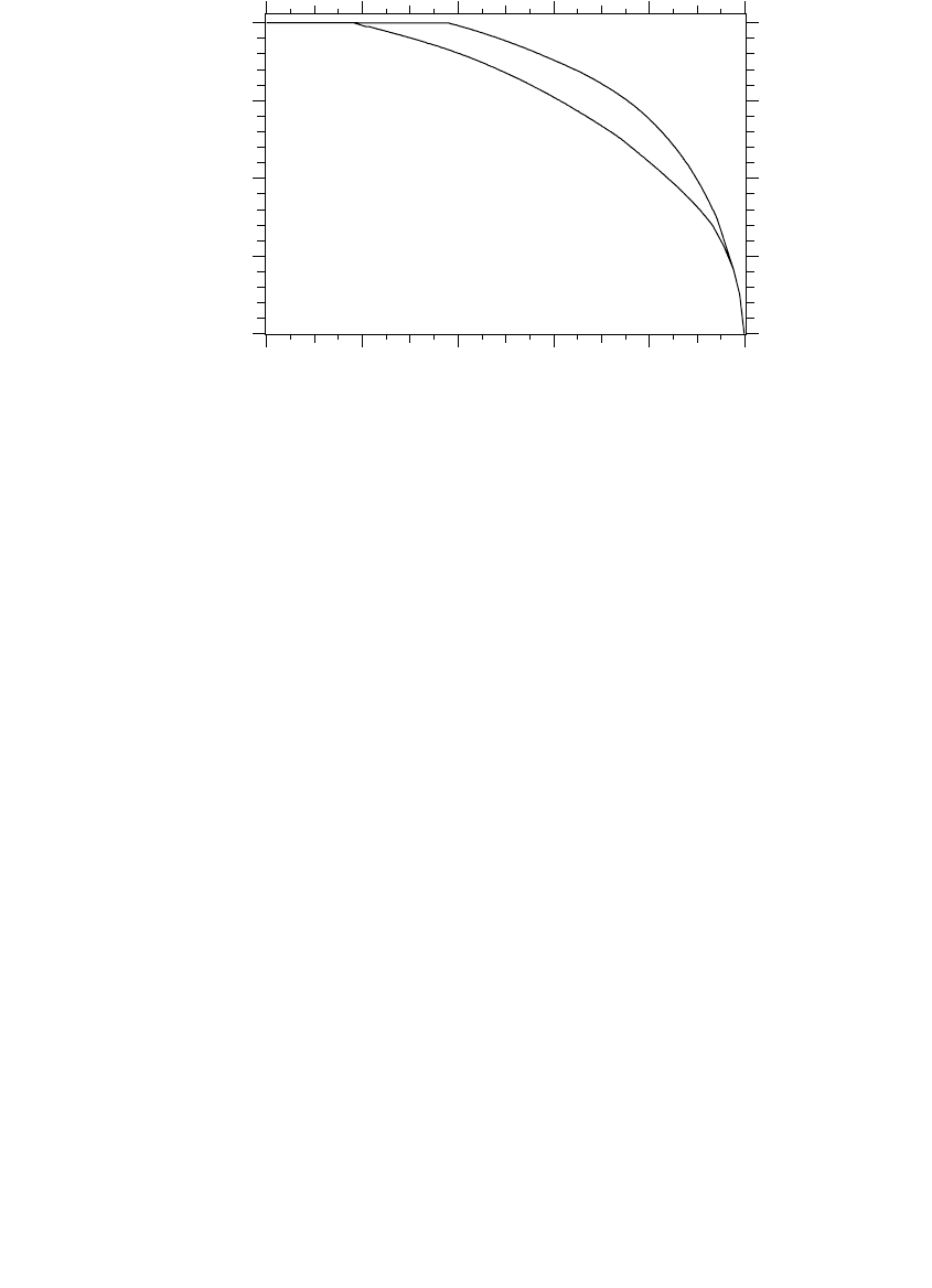
Published fuse curves are for no loading and an ambient temperature of
25∞C. Both loading and ambient temperature change the fuse melting char-
acteristic. Load current causes the most dramatic difference, especially when
a fuse is overloaded. Figure 8.5 shows the effect of loading on fuse melting
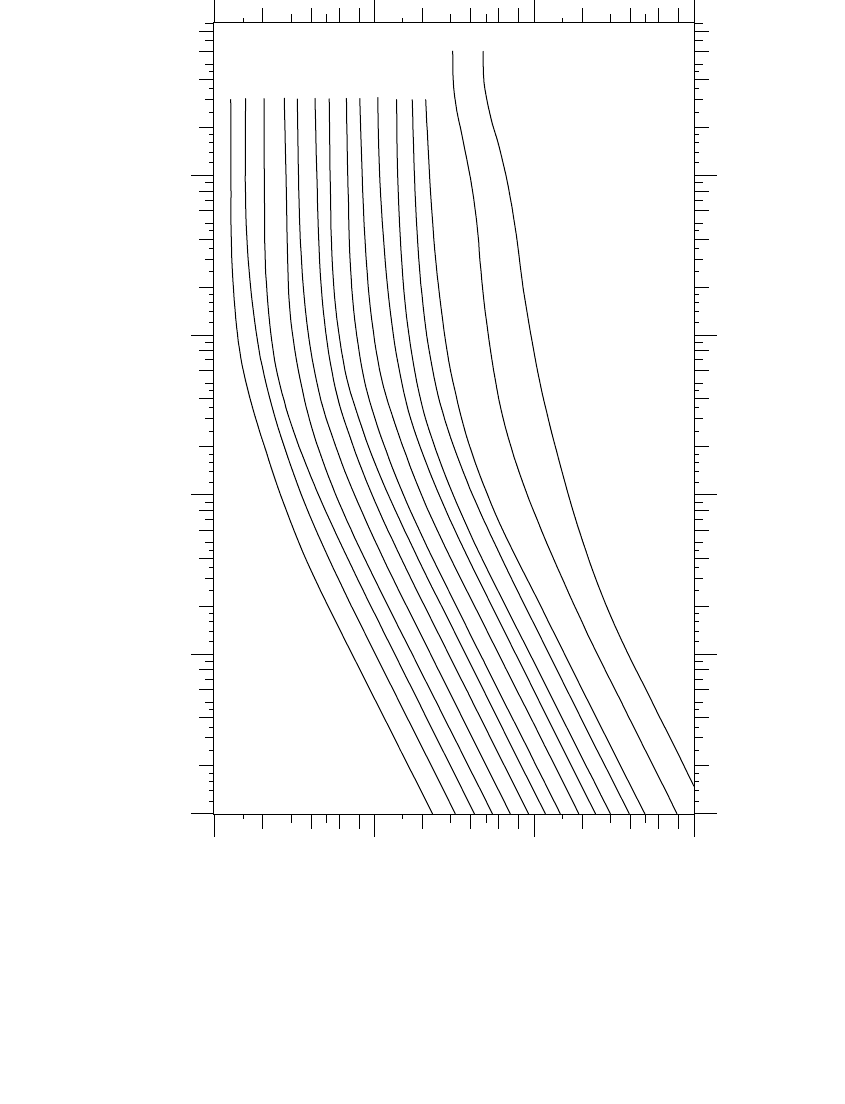
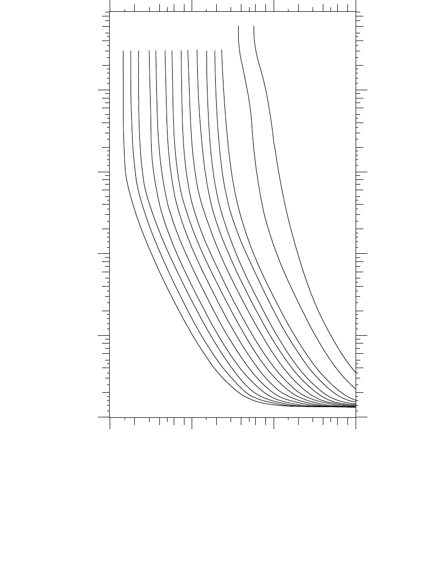
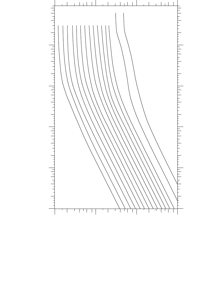
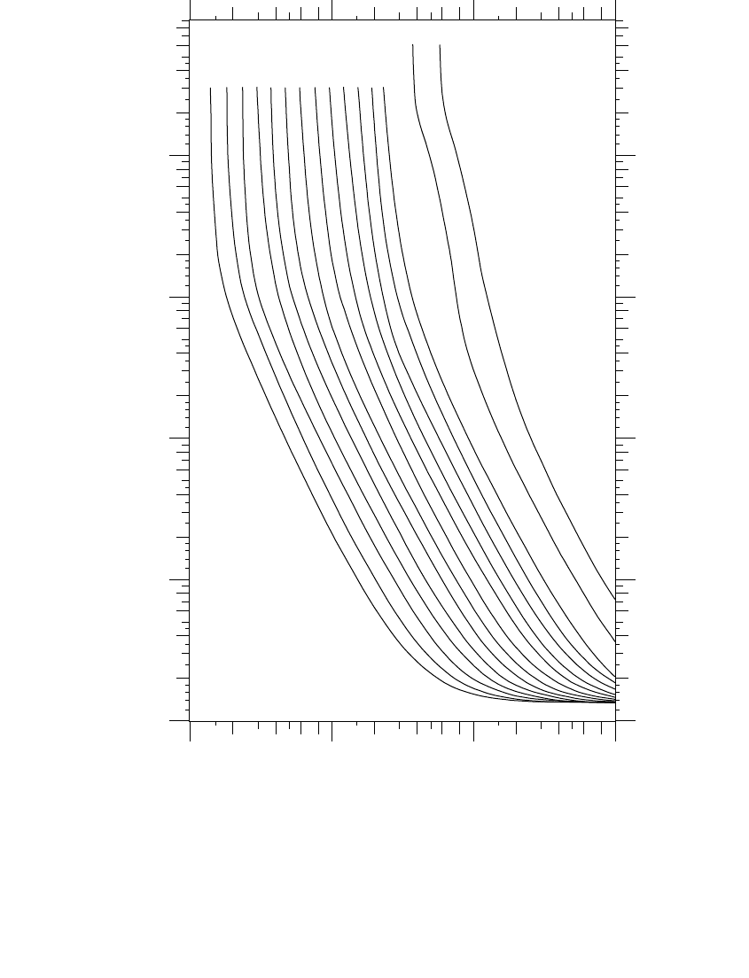
time. Figure 8.6 through Figure 8.9 show time-current curves for K and T links.
For operation outside of this ambient range, the fuse melting time changes.
The melting characteristic of tin fuse links changes 3.16% for each 10∞C above
or below 25∞C, so a fuse operating in a 50∞C ambient will operate in 92% of
the published time (100% 3.16%). Silver links are less sensitive to tem-
perature (0.9% melting change for each 10∞C above or below 25∞C).
The I
2
t of a fuse is often needed to coordinate between fuses. Table 8.4
shows the minimum melt I
2
t of K and T links estimated from the time-current
curves at 0.01 sec. This number is also useful to estimate melting character-
istics for high currents below the published time-current characteristics,
which generally have a minimum time of 0.01 sec.
The 6, 10, 15, 25, 40, 65, 100, 140, and 200-A fuses are standard ratings that
are referred to as preferred fuses. The 8, 12, 20, 30, 50, and 80-A fuses are
intermediate fuses. The designations are provided because two adjacent fuses
(for those below 100 A) will not normally coordinate. A 40 and a 30-A fuse
will not coordinate, but a 40 and a 25-A fuse will coordinate up to some
maximum current. Most utilities pick a standard set of fuses to limit the
number of fuses stocked.
K or T links with tin fuse elements can carry 150% of the nominal current
rating indefinitely. It is slightly confusing that a 100-A fuse can operate
continuously up to 150 A. Overloaded fuses, although they can be safely
overloaded, operate significantly faster when overloaded, which could cause
miscoordination. In contrast to tin links, silver links have no continuous
overload capability.
-
25
10
1791_book.fm Page 390 Monday, August 4, 2003 3:20 PM
(C) 2004 by CRC Press LLC
Short-Circuit Protection 391
FIGURE 8.4
Minimum melt and total clearing curves for a T and K link (50 A).
T
K
10
+1
10
+2
10
+3
10
+4
0.01
0.1
1.0
10.0
100.0
Current, amps
Time, seconds
1791_book.fm Page 391 Monday, August 4, 2003 3:20 PM
(C) 2004 by CRC Press LLC
392 Electric Power Distribution Handbook
Other nonstandard fuses are available from manufacturers for special pur-
poses. One type of specialty fuse is a fuse even slower than a T link that is
used to provide better coordination with upstream circuit breakers or reclos-
ers in a fuse saving scheme. Another notable type of specialty fuse is a surge-
resistant fuse that responds slowly to fast currents (such as surges) but faster
to lower currents. These achieve better protection on transformers for sec-
ondary faults and faster operation for internal transformer failures while at
the same time reducing nuisance fuse operations due to lightning.
Expulsion fuses under oil are another fuse variation. These “weak-links”
are used on CSP (completely self-protected) transformers and some pad-
mounted and vault transformers. Since they are not easily replaced, they
have very high ratings — at least 2.5 times the transformer full load current
and much higher if a secondary circuit breaker is used.
Transformers on underground circuits use a variety of fuses. For pad-
mounted transformers, a common fuse is the replaceable Bay-O-Net style
expulsion fuse. The time-current characteristics of this fuse do not follow
one of the industry standard designations.
8.2.5.1 Fuse Cutouts
The cutout is an important part of the fuse interrupter. The cutout determines
the maximum interrupting capability, the continuous current capability, the
load-break capability, the basic lightning impulse insulation level (BIL), and
the maximum voltage. Cutouts are typically available in 100, 200, and 300-
A continuous ratings [ANSI standard sizes (ANSI C37.42-1989)].
FIGURE 8.5
Effect of loading on fuse melting time. (Adapted from Cooper Power Systems, Electrical Distri-
bution — System Protection, 3rd ed., 1990. With permission from Cooper Industries, Inc.)
tin
silver
0 20 40 60 80 100
0
50
100
150
200
Melting time in percent of published curves
Preload current in percent of link rating
1791_book.fm Page 392 Monday, August 4, 2003 3:20 PM
(C) 2004 by CRC Press LLC
Short-Circuit Protection 393
FIGURE 8.6
Minimum melt curves for K links. (S&C Electric Company silver links.)
6
8
10
12
15
20
25
30
40
50
65
80
100
140 200
10
+1
10
+2
10
+3
10
+4
0.01
0.1
1.0
10.0
100.0
Current, amps
Time, seconds
1791_book.fm Page 393 Monday, August 4, 2003 3:20 PM
(C) 2004 by CRC Press LLC
394 Electric Power Distribution Handbook
FIGURE 8.7
Maximum total clear curves for K links. (S&C Electric Company silver links.)
6
8
10
12
15
20
25
30
40
50
65
80
100
140 200
10
+1
10
+2
10
+3
10
+4
0.01
0.1
1.0
10.0
100.0
Current, amps
Time, seconds
1791_book.fm Page 394 Monday, August 4, 2003 3:20 PM
(C) 2004 by CRC Press LLC
Short-Circuit Protection 395
FIGURE 8.8
Minimum melt curves for T links. (S&C Electric Company silver links.)
6
8
10
12
15
20
25
30
40
50
65
80
100
140 200
10
+1
10
+2
10
+3
10
+4
0.01
0.1
1.0
10.0
100.0
Current, amps
Time, seconds
1791_book.fm Page 395 Monday, August 4, 2003 3:20 PM
(C) 2004 by CRC Press LLC
396 Electric Power Distribution Handbook
FIGURE 8.9
Maximum total clear curves for T links. (S&C Electric Company silver links.)
6
8
10
12
15
20
25
30
40
50
65
80
100
140 200
10
+1
10
+2
10
+3
10
+4
0.01
0.1
1.0
10.0
100.0
Current, amps
Time, seconds
1791_book.fm Page 396 Monday, August 4, 2003 3:20 PM
(C) 2004 by CRC Press LLC