Short T.A. Electric Power Distribution Handbook
Подождите немного. Документ загружается.


Short-Circuit Protection 417
a downstream line recloser. Consider a station recloser R1 and a downstream
line recloser R2 each with one fast curve (A) and two delayed curves (B). If
a permanent fault occurs downstream of R2, R2 will first operate on its A
curve. If the fast curves of R1 and R2 are coordinated, R1 will not operate.
After a delay, R2 recloses. The fault is still there, so R2 operates on its delayed
curve (its B curve). Now, R1 does operate because it is on its A curve which
operates before R2’s B curve. After R1 recloses, R2 should then clear the
fault on its B curve, which should operate before R1’s B curve. The fault is
still cleared properly, but customers upstream of R2 have extra momentary
interruptions.
A more advanced form of coordination called sequence coordination removes
this problem. Sequence coordination is available on electronic reclosers and
also on digital relays controlling circuit breakers. With sequence coordina-
tion, the station device detects and counts faults — but does not open — for
a fault cleared by a downstream protector on the fast trip. If the fault current
occurs again (usually because the fault is permanent), the station device
switches to the time-overcurrent element because it counted the first as an
operation. Using this form of coordination eliminates the momentary inter-
ruption for the entire feeder for permanent faults downstream of a feeder
recloser. On a relay or recloser that has sequence coordination, if the device
senses current above some minimum trip setting and the current does not
last long enough to trip based on the device’s fast curve, the device advances
its control-sequence counter as if the unit had operated on its fast curve. So
when the downstream device moves to its delayed curve, the upstream
device with sequence coordination also is operating on its delayed curve.
With sequence coordination, for the fast curves, the response curve of the
upstream device must still be slower than the clearing curve of the down-
stream device.
8.7 Fuse Saving vs. Fuse Blowing
Fuse saving is a protection scheme where a circuit breaker or recloser is used
to operate before a lateral tap fuse. A fuse does not have reclosing capability;
a circuit breaker (or recloser) does. Fuse saving is usually implemented with
an instantaneous relay on a breaker (or the fast curve on a recloser). The
instantaneous trip is disabled after the first fault, so after the breaker recloses,
if the fault is still there, the system is time coordinated, so the fuse blows.
Because most faults are temporary, fuse saving prevents a number of lateral
fuse operations.
The main disadvantage of fuse saving is that all customers on the circuit
see a momentary interruption for lateral faults. Because of this, many utilities
are switching to a fuse blowing scheme. The instantaneous relay trip is
disabled, and the fuse is always allowed to blow. The fuse blowing scheme
1791_book.fm Page 417 Monday, August 4, 2003 3:20 PM
(C) 2004 by CRC Press LLC
418 Electric Power Distribution Handbook
is also called trip saving or breaker saving. Figure 8.15 shows a comparison
of the sequence of events of each mode of operation. Fuse saving is primarily
directed at reducing sustained interruptions, and fuse blowing is primarily
aimed at reducing the number of momentary interruptions.
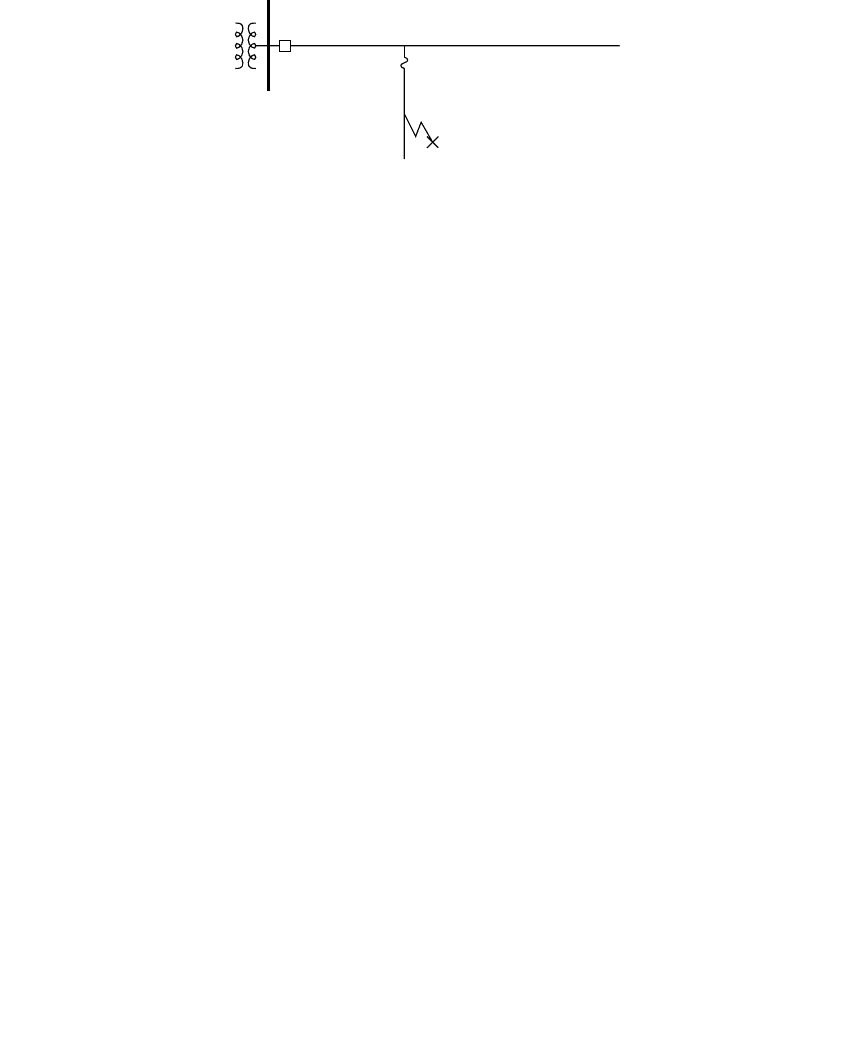
FIGURE 8.15
Comparison of the sequence of events for fuse saving and fuse blowing for a fault on a lateral.
Fault
Breaker or recloser
Lateral Fuse
Fuse Saving
Temporary fault
1. The circuit breaker operates on the instantaneous relay trip (before
the fuse operates).
2. The breaker recloses.
3. The fault is gone, so no other action is necessary.
Permanent fault
l. The circuit breaker operates on the instantaneous relay trip (before
the fuse operates).
2. The breaker recloses.
3. The fault is still there.
4. The instantaneous relay is disabled, so the fuse operates.
5. Crews must be sent out to fix the fault and replace the fuse.
Fuse Blowing
Temporary fault
1. The fuse operates.
2. Crews must be sent out to replace the fuse.
Permanent fault
1. The fuse operates.
2. Crews must be sent out to fix the fault and replace the fuse.
1791_book.fm Page 418 Monday, August 4, 2003 3:20 PM
(C) 2004 by CRC Press LLC

Short-Circuit Protection 419
8.7.1 Industry Usage
Until the late 1980s, fuse saving was almost universally used. As power
quality concerns grew, some utilities switched to a fuse blowing mode. An
IEEE survey on distribution protection practices that is done periodically
has shown a decrease in the use of fuse saving as shown in Table 8.11.
Another survey done by Power Technologies, Inc., in 1996 showed a mix-
ture of practices at utilities as shown in Table 8.12. A few used fuse blowing
because they indicated that fuse saving was not successful. Many of the
“mixed practices” utilities decided on a case-by-case basis. Many of these
normally used fuse saving but switched to fuse blowing if too many power
quality complaints were received.
8.7.2 Effects on Momentary and Sustained Interruptions
The change in the number of momentary interruptions can be estimated
simply by using the ratio of the length of the mains to the total length of the
circuit including all laterals. For example, if a circuit has 5 mi of mains and
10 mi of laterals, the number of momentaries after switching to fuse blowing
TABLE 8.11
IEEE Survey Results on the Percentage of Utilities
that Use Fuse Saving
Survey Year
Percent of Utilities
Using Fuse Saving
1988 91
1994 71
2000 66
Sources: IEEE Working Group on Distribution Protection,
“Distribution Line Protection Practices — Industry Sur-
vey Results,” IEEE Transactions on Power Delivery, vol. 3,
no. 2, pp. 514–24, April 1988; IEEE Working Group on
Distribution Protection, “Distribution Line Protection
Practices — Industry Survey Results,” IEEE Transactions
on Power Delivery, vol. 10, no. 1, pp. 176–86, January 1995;
Report to the IEEE working group on system perfor-
mance, 2002.
TABLE 8.12
1996 Survey on the Usage of Fuse Saving
Use fuse saving 40%
Use a mixture 33%
Use fuse blowing 27%
Source: Short, T. A., “Fuse Saving and Its Effect
on Power Quality,” EEI Distribution Committee
Meeting, 1999.
1791_book.fm Page 419 Monday, August 4, 2003 3:20 PM
(C) 2004 by CRC Press LLC

420 Electric Power Distribution Handbook
would be 1/3 of the number of momentaries with fuse saving (5/(5+10) =
1/3). This assumes that the mains and laterals have the same fault rate; if
the fault rate on laterals is higher (which it often is because of less tree
trimming, etc.), the number of momentaries is even less. Note how dramat-
ically we can reduce momentaries by using fuse blowing. No other methods
can so easily eliminate 30 to 70% of momentaries. The effect on reliability of
going to a fuse blowing scheme is more difficult to estimate. Fuse blowing
increases the number of fuse operations by 40 to 500% (Dugan et al., 1996;
Short, 1999; Short and Ammon, 1997). This will increase the average fre-
quency of sustained interruptions by 10 to 60%. Note that there are many
variables that can change the ratios. One example is given in Figure 8.16.
Note that the effect on sustained interruptions is not equally distributed.
Customers on the mains see no difference in the number of permanent
interruptions. Customers on long laterals may have many more sustained
interruptions with a fuse-blowing scheme.
8.7.3 Coordination Limits of Fuse Saving
One of the main reasons that utilities have decided not to use fuse saving is
that it is difficult to make it work. Fuses clear quickly relative to circuit
breakers, so where fault currents are high, the fuse blows before the breaker
trips. This results in a fuse operation and a momentary interruption for all
customers on the circuit. K links, the most common lateral fuses, are fast
fuses. Most distribution circuit breakers take 5 cycles to clear. For fuse saving
to work, the breaker must open before the fuse blows, so the fuse needs to
survive for the time it takes the instantaneous relay to operate (about one
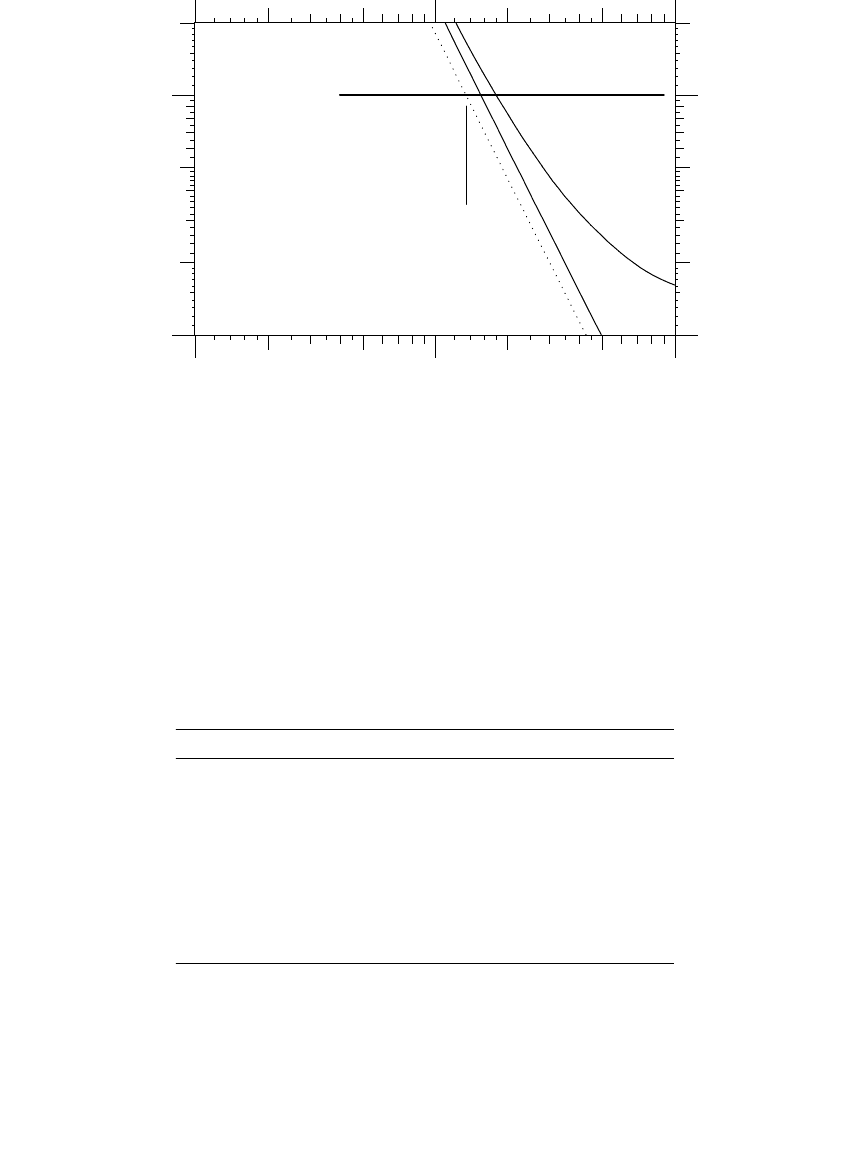
cycle) plus the 5 cycles for the breaker. As an illustration, Figure 8.17 shows
the limit of coordination of a 5-cycle breaker and a 100 K fuse. Fuse saving
only coordinates for faults below 1354 A. Smaller fuses have lower current
limits. Note that the breaker time is coordinated with the damage time of
the fuse.
FIGURE 8.16
Comparison of fuse saving and fuse blowing on a hypothetical circuit. Mains: 10 miles (16.1 km),
fault rate = 0.5/mile/year (0.8/km/year), 75% temporary. Taps: 10 miles (16.1 km) total, 20
laterals, fault rate = 2/mile/year (3.2/km/year), 75% temporary. It also assumes that fuse saving
is 100% successful.
127%
27%
Fuse Blowing
Fuse Blowing
Sustained Interruptions
100%
100%
Fuse Saving
Fuse Saving
Momentary Interruptions
1791_book.fm Page 420 Monday, August 4, 2003 3:20 PM
(C) 2004 by CRC Press LLC
Short-Circuit Protection 421
Table 8.13 and Table 8.14 show the limits of coordination of several com-
mon lateral fuses for a standard circuit breaker (5 cycle) and for a fast
breaker/relay combination (3-cycle circuit breaker and 1-cycle relay). Also
shown are translations of these fault currents into distances from the sub-
station at 12.47 kV (assuming an 8-kA fault level at the substation). Note
FIGURE 8.17
Coordination of a 100K lateral fuse with a 5-cycle circuit breaker.
TABLE 8.13
Maximum Fault Currents and Critical Distances for Fuse
Saving Coordination for Several Common Fuse Links for a 5-
Cycle Circuit Breaker and a 1-Cycle Relay Time
Fuse I
c
, A d
c
, mi d
c
, km Fuse I
c
, A d
c
, mi d
c
, km
20 K 254 26.5 42.6 20 T 433 15.5 25.0
25 K 323 20.8 33.5 25 T 552 12.2 19.6
30 K 398 16.9 27.2 30 T 699 9.6 15.5
40 K 520 12.9 20.8 40 T 896 7.5 12.1
50 K 665 10.1 16.3 50 T 1125 6.0 9.7
65 K 816 8.3 13.3 65 T 1428 4.8 7.7
80 K 1078 6.3 10.1 80 T 1790 3.8 6.2
100 K 1354 5.0 8.1 100 T 2277 3.1 4.9
140 K 2162 3.2 5.2 140 T 3447 2.1 3.4
200 K 3401 2.1 3.5 200 T 5436 1.5 2.4
Note: I
c
= Maximum current where fuse saving works. d
c
= Distance
from the substation where fuse saving starts to work for 12.47-
kV, 500-kcmil overhead line.
Source: Copyright © 2003. Electric Power Research Institute. 1001665.
Power Quality Improvement Methodology for Wire Companies. Reprinted
with permission.
100 K
Maximum
coordination
current
Breaker + relay time = 0.1 s
10
+2
10
+3
10
+4
2255
0.01
0.1
0.02
0.2
0.05
Current, amps
Time, seconds
1791_book.fm Page 421 Monday, August 4, 2003 3:20 PM
(C) 2004 by CRC Press LLC

422 Electric Power Distribution Handbook
that only the larger fuses shown (greater than 100 A) will coordinate for
significant portions of the feeder. Smaller fuses used as second and third
level fuses do not coordinate over the length of most feeders. The situation
is even worse at higher voltages. At 24.94 kV, the distances in Table 8.13 and
Table 8.14 are doubled, so fuse saving is more difficult to achieve at higher
voltages. Reclosers are faster than standard 5-cycle breakers — the 4-cycle
total operating time in Table 8.14 is representative of many reclosers.
If smaller K links are used such as 100K and 65K fuses (the most common
lateral fuses), then fuse saving is not going to work very well. In that case,
why use it? There is no sense in having a momentary every time a fuse blows
(which is what will happen since the circuit breaker is not fast enough to
save the fuse).
8.7.4 Long-Duration Faults and Damage with Fuse Blowing
Fuse blowing has drawbacks: faults on the mains can last a long time. With
fuse saving, main-line faults normally clear in 5 to 7 cycles (0.1 sec) on the
first shot with the instantaneous element. With fuse blowing, this same fault
may last for 0.5 to 1 sec. Much more damage at the fault location occurs
during this extra time. Some of the problems that have been identified are
• Conductor burndowns — At the fault, the heat from the fault current
arc burns the conductor enough to break it, dropping it to the
ground.
• Damage of inline equipment — The most common problem has been
with inline hot-line clamps. If the connection is not good, the high-
current fault arc across the contact can burn the connection apart.
TABLE 8.14
Maximum Fault Currents and Critical Distances for Fuse Saving Coordination for
Several Common Fuse Links for a 3-Cycle Circuit Breaker and a 1-Cycle Relay Time
Fuse I
c
, A d
c
, mi d
c
, km Fuse I
c
, A d
c
, mi d
c
, km
20 K 332 20.3 32.6 20 T 565 11.9 19.2
25 K 424 15.9 25.5 25 T 723 9.3 15.0
30 K 522 12.9 20.8 30 T 920 7.4 11.8
40 K 682 9.9 15.9 40 T 1175 5.8 9.3
50 K 875 7.7 12.4 50 T 1479 4.6 7.4
65 K 1070 6.3 10.2 65 T 1878 3.7 5.9
80 K 1407 4.8 7.8 80 T 2346 3.0 4.8
100 K 1763 3.9 6.3 100 T 2975 2.4 3.9
140 K 2823 2.5 4.1 140 T 4522 1.7 2.7
200 K 4409 1.7 2.8 200 T 7122 1.3 2.0
Note: I
c
= Maximum current where fuse saving works. d
c
= Distance from the substation
where fuse saving starts to work for 12.47-kV, 500-kcmil overhead line.
Source: Copyright © 2003. 1001665. Power Quality Improvement Methodology for Wire Companies.
Reprinted with permission.
1791_book.fm Page 422 Monday, August 4, 2003 3:20 PM
(C) 2004 by CRC Press LLC
Short-Circuit Protection 423
• Station transformers — Extra duty on substation transformers
• Evolving faults — Ground faults are more likely to become two- or
three-phase faults.
• Underbuilt — Faults on underbuilt distribution are more likely to
cause faults on the transmission circuit above due to rising arc gases.
A fault current arc will expand after it is initiated. It has been found that
the growth of the arc is generally in the vertical direction, and the growth
is primarily a function of time and not of current or voltage [(Drouet and
Nadeau, 1979) and Chapter 7]. The growth of the arc means that a 0.1-sec
fault on the instantaneous trip (with fuse saving) is less likely to involve
other phases or other circuits than a 0.2 to 1-sec fault on the time-delay trip
(with fuse blowing).
8.7.5 Long-Duration Voltage Sags with Fuse Blowing
With fuse blowing, voltage sags last longer, especially for faults on the three-
phase mains, which have to be cleared by phase or ground time-overcurrent
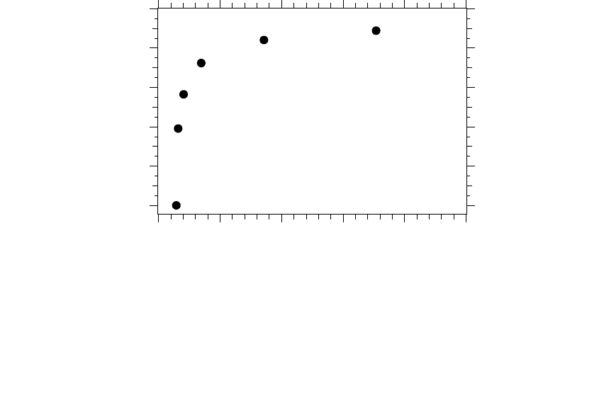
elements. An example is shown in Figure 8.18 where voltage sag magnitudes
and durations are shown for faults at various distances from a substation
using fuse blowing. For the same circuit with fuse saving, all of the faults
would have cleared in 0.1 sec. For a fault at the substation, the duration
triples. For a fault one mile (1.6 km) from the substation, the duration qua-
FIGURE 8.18
Magnitudes and durations of substation bus voltage sags for ground faults applied at the given
distance with a fuse-blowing scheme. For the same circuit with fuse saving, all of the faults
would clear in 0.1 sec. Assumptions: 12.47 kV, 500 kcmil, all-aluminum conductors. Ground
relay: CO-11, TD = 5, pickup = 300 A.
0 mi (0.0km)
0.5 mi (0.8km)
1.0 mi (1.6km)
2.0 mi (3.3km)
4.0 mi (6.6km)
6.0 mi (9.9km)
0 1 2 3 4 5
0.0
0.2
0.4
0.6
0.8
1.0
Sag duration, seconds
Voltage magnitude
[per unit]
1791_book.fm Page 423 Monday, August 4, 2003 3:20 PM
(C) 2004 by CRC Press LLC

424 Electric Power Distribution Handbook
druples. The situation is worse for phase-to-phase faults and three-phase
faults because they must be cleared by the phase relays which are generally
slower.
8.7.6 Optimal Implementation of Fuse Saving
In order to get a fuse saving scheme to work, it is necessary to get the
substation protective device to open before fuses operate. We can achieve
this in several ways:
• Slow down the fuse — Use big, slow fuses (such as a 140 or 200 T)
near the substation to ensure proper coordination.
• Faster breakers or reclosers — If three-cycle circuit breakers are used
instead of the normal 5-cycle breakers, fuse saving coordination is
more likely. Some reclosers are even faster than 3-cycle breakers.
• Limit fault currents:
• Open station bus ties: An open bus tie will reduce the fault
current on each feeder and make fuse saving easier. This is the
normal operating mode for most utilities.
• Use a transformer neutral reactor: A neutral reactor reduces the
fault current for single-phase faults (all faults on single-phase taps).
• Use line reactors: This reduces the fault current for all types of
faults. This has been an uncommon practice. An added advan-
tage, reactors reduce the impact of voltage sags for faults on
adjacent feeders.
• Specify higher impedance transformers.
We can employ other strategies to limit the impact of momentary inter-
ruptions:
• More downstream reclosers — Extra downstream devices will reduce
the number of momentaries for customers near the substation. It is
important to coordinate reclosers with the upstream device (includ-
ing sequence coordination).
• Single-phase reclosers
• Immediate reclose
• Switch to a fuse blowing scheme on poor feeders — For a feeder with
many momentaries, disable the instantaneous relay for a time
period. Identify poorly performing parts of the circuit during this
time. The blown branch fuses provide a convenient fault location
method. Once the poor performing sections are identified and
improved, switch the circuit back to fuse saving.
1791_book.fm Page 424 Monday, August 4, 2003 3:20 PM
(C) 2004 by CRC Press LLC

Short-Circuit Protection 425
8.7.7 Optimal Implementation of Fuse Blowing
Several strategies can optimize a fuse blowing scheme:
• Fast fuses (or current-limiting fuses) — If smaller or faster fuses are
used, faults clear faster, so voltage sag durations are shorter. Current-
limiting fuses also limit the magnitude and duration of the sag. Be
careful not to fuse too small, or fuses will operate unnecessarily due
to loading, inrush, and cold load pickup. Note that if smaller fuses
are used, it is difficult to switch back to a fuse-saving scheme.
• Covered wire or small wire — Watch burndowns on circuits with
covered wire or small wire that is protected by the station circuit
breaker or recloser. If either of these cases exists, use a modified fuse
blowing scheme with a time-delayed instantaneous element (see the
next section).
• Use single-phase reclosers on longer laterals — A good way of main-
taining some of the reliability of a fuse-saving scheme is to use
single-phase reclosers instead of fuses on longer taps. Then, tempo-
rary faults on these laterals do not cause permanent interruptions
to those customers.
• More fuses — Add more second and third level fuses to segment the
circuit more.
• Track lateral operations — Temporary faults on fused laterals cause
sustained interruptions. In order to minimize the impacts on lateral
customers, track interruptions by lateral. Identify poorly perform-
ing laterals, patrol poor sections, then add tree trimming, animal
guards, etc.
8.8 Other Protection Schemes
8.8.1 Time Delay on the Instantaneous Element (Fuse Blowing)
An alternative implementation of a fuse blowing scheme is to use a time
delay on the instantaneous trip (rather than removing the instantaneous trip;
a definite-time overcurrent relay also could do the same function) (Engel-
man, 1990). Faults do not last as long as they would if the relay went to a
time-overcurrent element; there is less chance of wire burndowns, and volt-
age sags are of shorter duration for faults on the mains. A common delay is
0.1 sec.
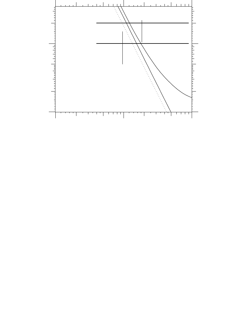
An example implementation is shown in Figure 8.19 where a 0.1-sec delay
is added to the instantaneous. A 100K fuse link is also shown. For the 100K
link, the scheme is actually a mixture of fuse saving and fuse blowing. For
fault currents above roughly 1700 A, it is a fuse blowing scheme (the fuse
1791_book.fm Page 425 Monday, August 4, 2003 3:20 PM
(C) 2004 by CRC Press LLC
426 Electric Power Distribution Handbook
clears before the instantaneous relay operates). For currents below 1000 A,
the scheme is a fuse saving scheme (the circuit breaker trips before the fuse
is damaged). Between 1000 and 1700 A, one or both devices operate.
Another option sometimes used with this scheme is a high-set instantaneous.
The high-set instantaneous has no time delay and is set to clear faults close to
the station. This removes the most damaging faults quickly (because they are
the most likely to cause damage and cause the most severe voltage sags).
Using a time delay is a better fuse saving scheme than just removing the
instantaneous relay. The disadvantage, and the reason that it is not imple-
mented as much, is that it is usually more difficult and costly to implement.
For electromechanical relays, another timer relay must be added, and the
relay scheme must be engineered. Many digital relays ease the implemen-
tation since they have this time-delay option available.
8.8.2 High-Low Combination Scheme
Another option is to use fuse blowing at the substation and fuse saving at
downstream reclosers (Burke, 1996).
• Substation fuse blowing — Fault currents are high near the substation,
so it is difficult to get fuse saving to work here.
FIGURE 8.19
Example of a delayed instantaneous element used for fuse blowing.
100 K
Breaker + relay time
+ delay = 0.2 s
Relay delay = 0.1 s
Fuse saving
below this current
Fuse blowing
above this current
10
+2
10
+3
10
+4
2255
0.01
0.1
0.02
0.2
0.05
Current, amps
Time, seconds
1791_book.fm Page 426 Monday, August 4, 2003 3:20 PM
(C) 2004 by CRC Press LLC