Short T.A. Electric Power Distribution Handbook
Подождите немного. Документ загружается.


Short-Circuit Protection 407
8.4 Lateral Tap Fusing and Fuse Coordination
Utilities use two main philosophies to apply tap fuses: fusing based on load
and standardized fusing schedules. With fusing based on load, we pick a
fuse based on some multiplier of peak load current. The fuse should not
operate for cold-load pickup or inrush to prevent nuisance operations. As
an example, one utility sizes fuses based on 1.5 times the current from the
phase with the highest connected kVA. With standardized fuse sizes, a typ-
ical strategy is to apply 100K links at all taps off of the mains (even if a tap
only has one 15-kVA transformer). If using second-level fusing, use 65K links
for these and 40K fuses for the third level. There is no clear winner; each
has advantages and disadvantages:
• Fusing based on load — This tends to fuse more tightly. High-imped-
ance faults are somewhat more likely to be detected. Nuisance fuse
operations are more likely, especially with utilities that tightly fuse
laterals. We are more likely to have load growth cause branch load-
ings to increase to the point of causing nuisance fuse operations.
Fusing based on load helps on circuits that have covered wire
because a smaller fuse helps protect against conductor burndown
(taps that are more heavily loaded usually have a larger wire, which
resists burndown).
• Standardized fuse sizes — It is simple: we spend less time coordinating
fuses, we do not constantly check loadings, and utilities have less
inventory. There is also less chance that the wrong fuse is installed
at a location. A disadvantage of this approach is that larger fuses
than needed are used at many locations, resulting in higher fault
damage at the arc location, longer voltage sags, and more stress on
in-line equipment.
Coordinating lateral tap fuses is generally straightforward. The fuse must
coordinate with the station recloser or circuit breaker relays. Station ground
relays are usually set to coordinate with the largest tap fuse. On the down-
stream side, a tap fuse should coordinate with the largest transformer fuse.
This usually is not a problem.
In addition to sizing a fuse to avoid nuisance operations and coordinating
with upstream and downstream protectors, we size fuses to ensure that the
fuses provide protection to the line section that they are protecting. The reach
of the fuse must exceed the length of the line section. Several methods are
used to quantify the reach of a fuse:
• Where the fuse will clear a bolted single line-to-ground fault in 3 sec
• Where the bolted single line-to-ground fault current is six times the
fuse rating
1791_book.fm Page 407 Monday, August 4, 2003 3:20 PM
(C) 2004 by CRC Press LLC

408 Electric Power Distribution Handbook
• Where the fuse will clear a single line-to-ground fault with a 30 W
resistance in 5 sec
In most situations, typical fuse sizes provide sufficient reach by any of
these methods. The first two methods are the best; the 30 W resistance is
overly conservative and difficult to apply.
Reliability needs dictate the number of fuses used. The most common
application for line fuses is at tap points. Occasionally, utilities fuse three-
phase mains, but a recloser is more commonly used for this purpose. In the
southwest U.S., in areas with few trees and little lightning, fuses may be
rarely used. This is the exception, not the rule. Most utilities fuse most taps
off the main line. Some go further and provide several levels of fusing,
especially utilities with heavy tree coverage. Returns diminish: too many
fuses leads to situations where fuses do not coordinate, and the extra fusing
does not increase reliability significantly. Cutouts themselves contribute to
causing faults by providing an easy location where animals, trees, and light-
ning cause faults, especially if they are poorly installed.
8.5 Station Relay and Recloser Settings
The main feeder circuit breaker relays (or recloser) must be set so that the
circuit breaker coordinates with downstream devices, coordinates with
upstream devices, and does not have trips from inrush or cold-load pickup.
Station relays almost always use phase and ground time-overcurrent relays.
Table 8.9 shows typical settings used by several utilities. Many utilities try
to use standardized relay settings at all distribution stations. This has the
TABLE 8.9
Time-Overcurrent and Instantaneous Station Relay Pickup Settings in Amperes
on the Primary at Several Utilities
Utility
Phase Ground
NotesTOC Inst. TOC Inst.
A 720 4000 480 4000 Assumes peak
current = 400 A
B 720 1200 360 1200 Full load =
300 to 400 A
C 600 none 300 530
D 960 1300 480 600
E 800 none 340 none
F 960 2880 240 1920
G ≥2.25 ¥
current rating
same
as TOC
≥ 0.6 ¥
current rating
same
as TOC
600 600 160 160 Typical settings
1791_book.fm Page 408 Monday, August 4, 2003 3:20 PM
(C) 2004 by CRC Press LLC

Short-Circuit Protection 409
advantage that relays are less likely to be set wrong, and there is less engi-
neering effort in a coordination study. Some other utilities set each relay
based on a coordination study.
Differences exist about the meaning of “peak load.” Some utilities base it
on the maximum design emergency load (which is typically something like
600 A). Others use the designed normal load (typically 400 A). Others may
base it on some percentage of the total connected distribution transformer kVA.
Instantaneous relay settings vary more than phase relay settings. Several
utilities also either disable or do not use an instantaneous relay setting. The
instantaneous relay pickup ranges from one to almost ten times the phase
relay pickup.
One reasonable set of base pickup settings is:
• Phase TOC (time-overcurrent) relay — Use two times the normal
designed peak load on the circuit.
• Ground TOC relay — Use 0.75 times the normal designed peak load
on the circuit.
• Instantaneous phase and ground relays — Use two times the TOC relay
pickups.
Settings any less than this are prone to false trips from cold-load pickup
and inrush.
In addition to avoiding nuisance trips, the relays (or recloser) must provide
protection to its line section (to the end of the line or to the next protective
device in series). Ensure that the relay has sufficient reach at the minimum
operating current of the relay.
For a phase relay, sufficient reach is achieved by ensuring that 75% of the
bolted line-to-line fault current at the end of the circuit is greater than the
relay’s pickup (its minimum operating current). So, if the line-to-line fault
current at the end of the circuit is 1000 A, the pickup of the relay should
be no more than 750 A. We use the line-to-line fault current because the
two types of faults not seen by the ground relay are the three phase and
the line to line. Of these, the line-to-line fault has the lower magnitude. The
75% factor provides a safety margin and allows some fault impedance.
Another approach is to ensure that the line-to-ground fault current at the
end of the circuit is less than the minimum operating current. The line-to-
ground fault current is less than the line-to-line fault current, which pro-
vides the safety margin.
For a ground relay, ensure that the relay pickup is less than 75% of the
line-to-ground fault current at the end of the line or to the next protective
device. The ground relay must also coordinate with the largest lateral fuse.
Feeders dedicated to supplying secondary networks, either grid or spot
networks, have similar settings as feeders supplying radial loads. Two main
differences are related to loading and the ground relay setting. The pickup
settings of station circuit breakers may have to account for higher peak loads.
1791_book.fm Page 409 Monday, August 4, 2003 3:20 PM
(C) 2004 by CRC Press LLC

410 Electric Power Distribution Handbook
Some utilities have phase relay pickups that are similar to radial circuits,
from 600 to 800 A, but some have settings above 900 A with one utility
having a 1680-A setting (Smith, 1999). Also, if feeders are supplying only
network load, and all network transformers are connected delta – grounded
wye, the unbalanced current seen by the ground relay is small. Utilities can
set a low ground relay setting; some have settings ranging from 40 to 80 A
(Smith, 1999). The main limitation on lowering the setting further is that
during line-to-ground faults, the unfaulted circuits will backfeed the fault
through the zero-sequence capacitance of that circuit. Lower ground-relay
settings also help detect turn-to-turn or layer-to-layer faults within the pri-
mary windings of network transformers.
8.6 Coordinating Devices
Several details often arise when coordinating specific devices. Normally, we
want to ensure that the downstream device clears before the upstream device
operates over the range fault currents available at the downstream device.
Time-current characteristics of both device normally show us how well two
devices coordinate. Because of device differences, some combinations require
slightly different approaches. We discuss some of the common combinations
in the sections that follow.
8.6.1 Expulsion Fuse–Expulsion Fuse Coordination
When coordinating two fuses, the downstream fuse (referred to as the pro-
tecting fuse) should operate before the upstream fuse (the protected fuse). To
achieve this goal, ensure that the total clear time of the protecting fuse is
less than the damage time of the protected fuse. The damage time is 75% of
the minimum melt time. An example for coordinating a 100K link with a
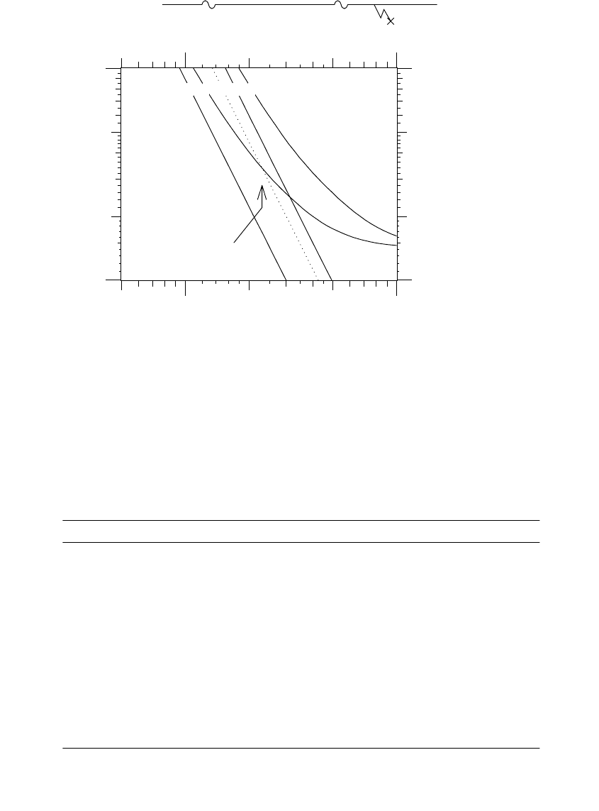
65K link is shown in Figure 8.12. Above a certain current, the two fuses do
not coordinate; the protected fuse could suffer damage or melt before the
protecting fuse can clear. For high fault currents, coordination is impossible
because both fuses can open. The example shows that above 2310 A, the
total clear curve of the 65K is above the damage curve of the 100K link.
Utilities live with this common miscoordination. Table 8.10 lists the maxi-
mum coordination currents between K links. In cases where fuses do not
coordinate, why have the second fuse? The second fuse still has some value;
it adds another sectionalizing point (for a fuse in a cutout), and for a down-
stream fault, it identifies the fault location to a smaller area. Also, the down-
stream fuse may operate without damaging the upstream fuse. The amount
of damage to the upstream fuse depends on the point of the waveform where
the fault occurs (the extra 1/2 + cycle waiting for a current zero causes the
extra heating to the protected fuse).
1791_book.fm Page 410 Monday, August 4, 2003 3:20 PM
(C) 2004 by CRC Press LLC
Short-Circuit Protection 411
FIGURE 8.12
Example of fuse coordination between a 100-K (the protected fuse) and a 65-K link (the pro-
tecting link).
TABLE 8.10
Maximum Fault Currents for Coordination between the Given K Fuse Links
10K 12K 15K 20K 25K 30K 40K 50K 65K 80K 100K 140K 200K
6K 170 310 460 640 840 1060 1410 1800 2230 2930 3670 5890 9190
8K 20 230 410 610 810 1040 1400 1790 2230 2930 3670 5890 9190
10K 40 300 550 780 1000 1370 1770 2220 2930 3670 5890 9190
12K 80 420 690 950 1330 1730 2190 2910 3650 5880 9190
15K 90 530 840 1250 1670 2120 2870 3640 5870 9190
20K 100 610 1120 1570 2040 2800 3590 5870 9190
25K 120 840 1380 1920 2710 3510 5830 9150
30K 240 1090 1690 2570 3380 5740 9110
40K 300 1240 2260 3210 5630 9010
50K 240 1750 2800 5500 8910
65K 970 2310 5210 8740
80K 420 4460 8430
100K 3550 7950
140K 4210
1 2 3 4 5
65 K
100 K
Maximum
coordination
current
10
+3
10
+4
255
0.01
0.1
0.02
0.05
1: 65K minimum melt
2: 65K total clearing
3: 100K damage time
4: 100K minimum melt
5: 100K total clearing
Current, amps
Time, seconds
Fault
"Protected" Fuse "Protecting" Fuse
Source
100 K 65 K
1791_book.fm Page 411 Monday, August 4, 2003 3:20 PM
(C) 2004 by CRC Press LLC

412 Electric Power Distribution Handbook
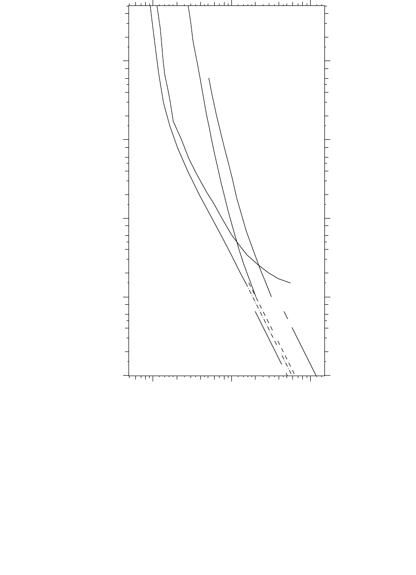
8.6.2 Current-Limiting Fuse Coordination
Coordinating two current-limiting fuses is similar to coordinating two expul-
sion links. Plot the time-current characteristics and ensure that the maximum
clearing time of the load-side fuse is less than 75% of the minimum-melting
time of the source-side fuse over the range of fault currents available at the
load-side fuse. The 75% factor accounts for damage to the source-side fuse.
Unlike expulsion links, current-limiting fuses can coordinate to very high
currents. For coordination at higher currents than are shown on published
time-current characteristics (operations faster than 0.01 sec), ensure that the
maximum clearing I
2
t of the load-side fuse is less than 75% of the minimum-
melt I
2
t of the source-side fuse. Manufacturers provide both of these I
2
t values
for current-limiting fuses.
Coordinating an expulsion link with a current-limiting fuse follows similar
principles. Because the melting and clearing characteristics of current-limit-
ing fuses are so much steeper than those of expulsion links, coordination is
sometimes difficult; the operating characteristic curves are more likely to
cross over. A load-side current-limiting fuse coordinates over a wide range
of fault current. For a source-side current-limiting fuse, the clearing-time
limitations of expulsion links (to about 0.8 cycles) prevent coordination at
high currents. For currents above this value, either both will operate, or just
the current-limiting fuse will operate.
Backup current-limiting fuse coordination requires special attention. To
ensure that the CLF does not try to operate for currents below its minimum
interrupting rating, the intersection of the expulsion fuse’s total-clearing
curve and the backup fuse’s minimum-melting curve must be greater than
the maximum interrupting rating of the backup fuse. Normally, we select
backup current-limiting fuses for use with expulsion links based on matched-
melt coordination. Select a backup current-limiting fuse that has a maximum
melting I
2
t below the maximum clear I
2
t of the expulsion element. Also, check
the time-current curves of the devices. The expulsion link should always
clear for fault currents in the low-current operating region, especially below
the minimum interrupting current of the current-limiting fuse.
With matched-melt coordination, the expulsion fuse always operates,
including when the backup current-limiting fuse operates. In overhead
applications with an expulsion fuse in a cutout, the dropout of the expulsion
fuse provides a visible indication when the fuse(s) operate. Also, the backup
fuse is unlikely to have full voltage across it.
The maximum melting I
2
t of expulsion links is not provided from curves
or data. To estimate this, take the minimum melting I
2
t calculated from the
minimum-melt curve at 0.0125 sec, and multiply by 1.2 for tin links or 1.1
for silver links. The multiplier allows for conservatism in minimum-melt
curves and for manufacturing tolerances.
Somewhat less conservatively, experience has shown that fuses coordinate
well if the maximum melt I
2
t of the expulsion link does not exceed twice the
minimum melt I
2
t of the backup fuse (IEEE Std. C37.48-1997). We can tighten
1791_book.fm Page 412 Monday, August 4, 2003 3:20 PM
(C) 2004 by CRC Press LLC

Short-Circuit Protection 413
up the backup fuse because, under most practical situations, the backup fuse
lets through significantly more I
2
t than its minimum-melt value.
Manufacturers of backup current-limiting fuses normally provide coordi-
nation recommendations for their fuses, but review of the coordination
approach is sometimes appropriate. Backup fuses often use a “K” nomen-
clature signifying the K link that it coordinates with. For example, a “25 K”
backup link coordinates with a K link rated at 25 A or less. Figure 8.13 shows
the time-current curves of a 40K expulsion link and the curves of one man-
ufacturer’s 40K backup current-limiting fuse. This graph extends below the
normal cutoff time of 0.01 sec to show how the fuses coordinate at high
currents. This example shows that the backup fuse does not coordinate using
the strict matched-melt criteria (the maximum melting time of the expulsion
link is more than the minimum melting time of the backup fuse). The min-
imum-melt I
2
t of the backup fuse is 1.6 times the minimum melt I
2
t of the
backup fuse, so it meets the relaxed matched-melt criteria since this ratio is
less than two.
The time-current curve crossover coordination allows a smaller backup cur-
rent-limiting fuse. As before, the intersection of the expulsion fuse’s total-
clearing curve and the backup fuse’s minimum-melting curve must be
greater than the maximum interrupting rating of the backup fuse. We do not
try to ensure that the backup fuse always melts. We can use a smaller fuse,
which reduces the I
2
t let through and reduces energy to faults. The backup
CLF operates for a wider range of short-circuit currents. With a smaller fuse,
the backup fuse can operate before the expulsion link melts for high fault
currents. Utilities often use time-current curve crossover coordination for
under-oil backup current-limiting fuses. In addition to lowering energy to
faults, crossover coordination extends the range of current-limiting fuse
protection to larger transformers.
For transformer protection, overload and secondary faults are also consid-
erations for backup current-limiting fuses. Secondary faults at the terminals
of the transformer should not damage or melt the backup CLF. One way to
do this is to ensure that at the total clearing time of the expulsion link with
the bolted secondary fault, the backup fuse’s minimum melting current is
at least 125% of the secondary fault current (Hi-Tech Fuses, 2002). Also,
overload should not damage or melt the backup CLF.
8.6.3 Recloser–Expulsion Fuse Coordination
Normally, we want the recloser’s fast curve (A curve) to clear before down-
stream fuses operate. This saves the fuse for temporary faults (we discuss
fuse saving in more detail later in this chapter). Select the delayed curve (B,
C, … ) to be above the clearing time of downstream fuses. A permanent fault
downstream of a fuse should blow the fuse, not lockout the recloser.
To open the recloser before the fuse blows, Cooper (1990) recommends
adjusting the A curve by multiplying the time by a factor of 1.25 for one fast
1791_book.fm Page 413 Monday, August 4, 2003 3:20 PM
(C) 2004 by CRC Press LLC
414 Electric Power Distribution Handbook
operation, a factor of 1.35 for two fast operations with a reclosing time greater
than or equal to 1 sec, and a factor of 1.8 for two fast operations with a
reclosing time from 25 to 30 cycles. For applications with two or more
delayed operations, the fast curve coordinates for fault currents up to the
point where the adjusted A curve crosses the expulsion fuse’s minimum-
melting curve.
FIGURE 8.13
Coordination between a 40-K expulsion link and a 40-K backup current-limiting fuse using the
relaxed matched-melt criteria.
1
2
3
4
1: Backup total clearing I
2
t
2: Expulsion minimum-melting time
3: Expulsion maximum-melting time
4: Backup minimum-melt I
2
t
40K expulsion link
40K backup
current-limiting fuse
10
+2
10
+3
10
+4
0.001
0.01
0.1
1.0
10.0
Current, amps
Time, seconds
1791_book.fm Page 414 Monday, August 4, 2003 3:20 PM
(C) 2004 by CRC Press LLC
Short-Circuit Protection 415
On hydraulically controlled reclosers, the trip-coil rating determines the
recloser’s “pickup.” Beyond that, hydraulically controlled reclosers have
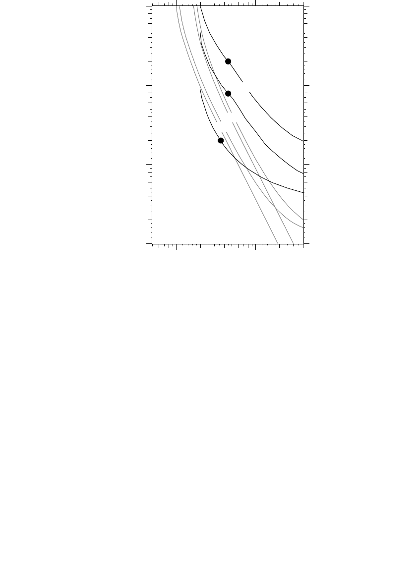
limited curve selections and no adjustments. Figure 8.14 shows average
clearing curves for a single-phase Cooper 4E hydraulically controlled
recloser overlayed on top of two K fuse links. For this example, only a
limited range of fuses coordinate for low and high fault currents. Fuses
larger than a 65K have significant overlap in the low-current area, leaving
more chance that the recloser could lock out for a fault on a lateral tap. The
slower delayed curves, such as the C curve shown, reduce the chance of
miscoordination for lower fault currents. For the fast-trip A curve, the 40K
link only coordinates with the fast curve for fault currents up to 360 A;
smaller links are worse. Since K links are significantly steeper than these
recloser curves, we must expect limited coordination for certain combina-
tions. In this instance, T links coordinate over a wider current range because
their time-current characteristics match the slope of the recloser character-
istics more accurately. Miscoordination is more problematic in the low-
current region. If the recloser locks out for faults downstream of a fuse,
FIGURE 8.14
Example of coordination between K links and a Cooper 4E single-phase hydraulic recloser with
a 100-A trip coil (A, B, and C curves shown).
40K
65K
100.0 1000.
0.01
0.1
1.0
10.0
C curve
B curve
1.25xA curve
Current, amps
Time, seconds
1791_book.fm Page 415 Monday, August 4, 2003 3:20 PM
(C) 2004 by CRC Press LLC

416 Electric Power Distribution Handbook
more customers are interrupted, and crews have a harder time finding the
fault (more area to patrol).
Reclosers with electronic controls and relayed circuit breakers offer more
flexibility. We can tailor tripping characteristics to coordinate over a wider
range of currents. Three-phase reclosers have a ground-trip element that can
increase the sensitivity of the recloser and also coordinate better with down-
stream fuses.
8.6.4 Recloser–Recloser Coordination
For coordinating two reclosers, the curve separation we need depends on
the type of recloser. For hydraulically-controlled reclosers that are series
coil operated, both operate if there is less than a 2-cycle separation; both
may operate for a separation of 2 to 12 cycles, and both coordinate properly
if there are more than 12 cycles of separation. For hydraulically-controlled
reclosers that use high-voltage solenoid closing (larger reclosers), we need
8 cycles of separation for coordination (if it is less than 2 cycles, both
devices operate). This data is for Cooper reclosers (Cooper Power Sys-
tems, 1990).
8.6.5 Coordinating Instantaneous Elements
Coordinating instantaneous relay elements or recloser fast curves is difficult.
By the nature of an instantaneous element, two in series will both operate
if the short-circuit current is above the pickup of both relays.
The most common way to coordinate two instantaneous elements is to
raise the pickup of the upstream element. Find a setting where the instan-
taneous relay will not operate for faults downstream of the second protective
device. The upstream relay cannot operate if its pickup is above the available
fault current at the location of the downstream element. For this strategy,
the instantaneous pickup on the element must be higher than its time-
overcurrent pickup. This rules out hydraulic reclosers, which have the same
pickup for the fast (A) curve and the delayed curves (B & C), but is not a
concern with electronic reclosers because they have the same flexibility as
relayed circuit breakers.
Rather than using an instantaneous relay element, we can perform the
“fast trip” function with a time-overcurrent relay with a fast characteristic.
Now, we might be able to coordinate the fast curve of a line recloser with
the substation circuit breaker or recloser.
As another way to coordinate two instantaneous elements, use a time delay
on the upstream instantaneous element. Choose enough time delay, 6 to 10
cycles, to allow the downstream device to clear before the station device
operates.
Even with coordinated fast curves (either using a delay or using a fast
TOC curve), nuisance momentary interruptions occur for faults cleared by
1791_book.fm Page 416 Monday, August 4, 2003 3:20 PM
(C) 2004 by CRC Press LLC