Stephen L. Herman, Bennie Sparkman. Electricity and Controls for HVAC-R (6th edition)
Подождите немного. Документ загружается.

250 SECTION 5 Control Components
coil, a magnetic eld is produced around the coil of
the relay. This magnetic eld closes the reed con-
tacts, which causes the triac to turn on. In this type
of solid-state relay, a magnetic eld is used to isolate
the control circuit from the load circuit instead of a
light beam.
The control voltage for most solid-state relays
ranges from about 3 to 32 volts and can be DC
or AC. If a triac is used as the control device, load
voltage ratings of 120 to 240 VAC are common
and current ratings can range from 5 to 25 amps.
Many solid-state relays have a feature known as
zero switching. Zero switching means that if
the relay is told to turn off when the AC voltage is
in the middle of a cycle, it will continue to conduct
until the AC voltage drops to a zero level and then
turn off. For example, assume the AC voltage is at
its positive peak value when the gate tells the triac
to turn off. The triac will continue to conduct until
the AC voltage drops to a zero level before actually
turning off. Zero switching can be a great advantage
when used with some inductive loads such as trans-
formers. The core material of a transformer can be
left saturated on one end of the ux swing if power
is removed from the primary winding when the AC
voltage is at its positive or negative peak. This can
cause inrush currents of up to 600% of the normal
operating current when power is restored to the
primary.
Solid-state relays are available in different case
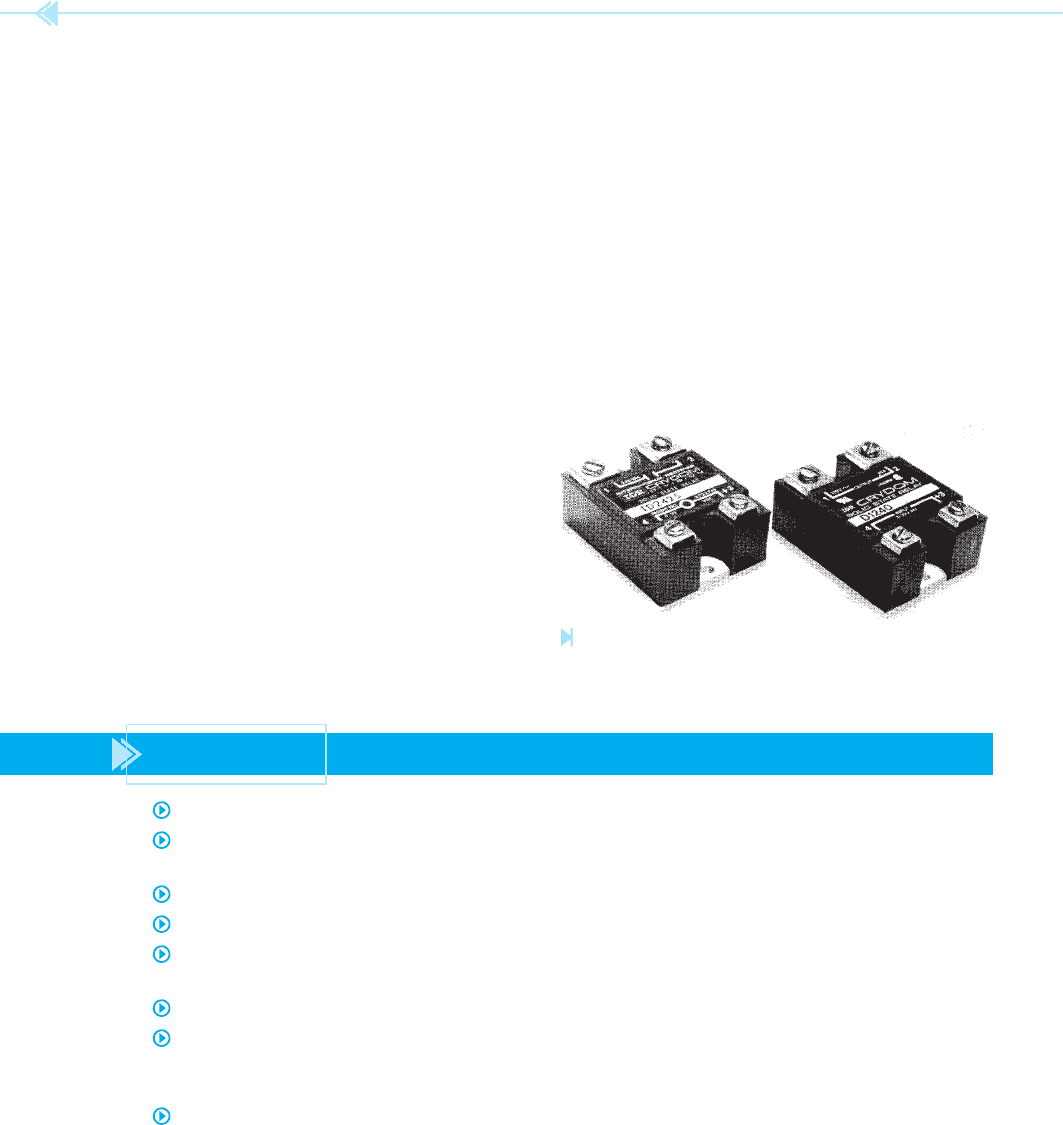
styles and power ratings. Figure 24–5 shows a
typical solid-state relay. Some solid-state relays are
designed to be used as time-delay relays. One of the
most common uses for the solid-state relay is the I/O
(eye-oh) track of a programmable controller, which
is to be covered in a later unit.
Figure 24–5
Solid-state relays. (Courtesy of International Rectifi er).
SUMMARY
Solid-state relays have no moving parts.
Solid-state relays are sealed against dirt and moisture and are resistant to mechanical
shock and vibration.
The control side of a solid-state relay is totally isolated from the load side.
Solid-state relays used to control AC loads use a triac connected in series with the load.
Solid-state relays used to control DC loads use a power transistor connected in series with
the load.
Many solid-state relays use a light-emitting diode (LED) as the control device.
Opto-isolation is used to separate the load side of the circuit from the control side. This
prevents any electrical noise from being transferred from the load side to the control side
of the circuit.
Solid-state relays are generally used in the I/O track of programmable controllers.

UNIT 24 The Solid-State Relay 251
KEY TERMS
light-emitting
diode (LED)
opto-isolated
power transistor
reed relay
solid-state relay
triac
zero switching
REVIEW QUESTIONS
1. What electronic component is used to control the output of a solid-state relay used to
control a DC voltage?
2. What electronic component is used to control the output of a solid-state relay used to
control an AC voltage?
3. Explain opto-isolation.
4. Explain magnetic isolation.
5. What is meant by zero switching?

252
The transformer is a device that has the ability to
change the value of AC voltage and current without
a change of frequency. Most of the transformers
used in the air conditioning and refrigeration eld
are known as
isolation transformers. This
means that the primary and secondary windings
are magnetically coupled but electrically isolated
from each other. Figure 25–1 illustrates the basic
principle of operation of a transformer. This trans-
former contains two separate windings, the primary
and the secondary. The primary is the winding that
is connected to the power source and brings power
to the transformer. The secondary winding is used
to supply power to the load. Notice that there is no
electrical connection between the two windings. If
one lead of an ohmmeter is connected to one of the
primary leads and the other ohmmeter lead is con-
nected to one of the secondary leads, the
ohmmeter
OBJECTIVES
After studying this unit the student should
be able to:
Discuss the principle of operation
of a transformer
Defi ne mutual induction
Discuss the voltage and current
relationships in a transformer
Find values of voltage, current,
and turns of wire using transformer
formulas and Ohm’s law
Connect an industrial control
transformer for operation on low and
high voltage
Perform an ohmmeter test on a control
transformer
The Control
Transformer
UNIT 25
UNIT 25 The Control Transformer 253
SECONDARY
LAMINATED CORE
TO LOAD
PRIMAR
Y
should indicate no continuity between the two
windings.
PRINCIPLE OF OPERATION
The transformer operates by magnetic induction.
When current ows through the primary winding,
a magnetic eld is created in the winding. Because
the secondary winding is wound on the same core
as the primary, the magnetic eld of the primary
induces a voltage into the secondary. This action
is known as mutual induction. The amount of
voltage induced into the secondary is determined
by the ratio of the number of turns of wire in the
primary as compared with the number of turns of
wire in the secondary. For example, assume that the
primary winding shown in Figure 25–1 contains
120 turns of wire and is connected to 120 volts AC.
This means that each turn of the primary has a volt-
age drop of 1 volt. If the secondary winding also has
120 turns of wire, and 1 volt is induced into each
turn, then the output voltage of the secondary is
120 volts also. This transformer has a turns ratio of
1:1, which is to say that the primary contains 1 turn
of wire for each turn of wire in the secondary.
Now assume that the number of turns of wire in
the secondary has been changed to 60. If the number
of turns in the primary has not been changed, there
Figure 25–1
A basic transformer.
(Source: Delmar/Cengage Learning)
Figure 25–2
Schematic for transformer.
(Source: Delmar/Cengage Learning)
is still 1 volt for each turn of wire. This will produce a
secondary voltage of 60 volts (60 ⫻ 1 ⫽ 60).
If the number of turns of wire on the secondary
is changed to 240, the output voltage of the sec-
ondary will be 240 volts (240 ⫻ 1 ⫽ 240). Notice
that the transformer has the ability to increase or
decrease the amount of the secondary voltage. If
the voltage of the secondary is less than the primary
voltage, the transformer is known as a step-down
transformer. If the secondary voltage is greater
than the primary voltage, it is known as a step-up
transformer.
VOLTAGE AND CURRENT
RELATIONSHIPS
It would rst appear that the transformer has the
ability to give more than it receives. This is not the
case, however. Transformers are extremely ef cient
devices; they generally operate at 95% to 98% ef -
ciency. For this reason, when working with trans-
formers it is generally assumed that the power out
of the transformer is equal to the power being put
into the transformer.
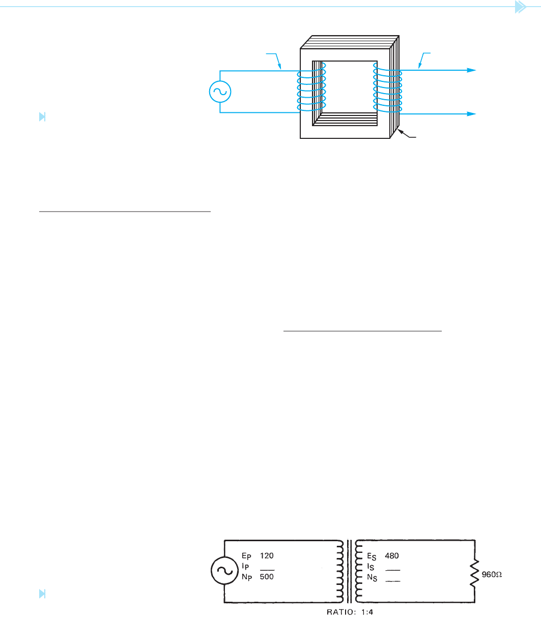
Figure 25–2 shows the schematic symbol for a
transformer. The primary has been connected to
120 volts. The secondary has a voltage of 480 volts
and is connected to a load resistor of 960 ohms.

254 SECTION 5 Control Components
This transformer has a turns ratio of 1:4, which is
to say that there is 1 turn of wire in the primary for
every 4 turns of wire in the secondary. The amount
of current in the secondary (I
S
) can be computed by
using Ohm’s law.
I ⫽
E
__
R
I ⫽
480
____
960
I ⫽ .5 amp
Question: If the secondary of this transformer has a
current ow of .5 amp, how much current is required
in the primary? There are actually several methods
that can be used to solve this problem. The most
accepted method is to use the formulas shown in
Figure 25–3. Because both the primary and second-
ary voltages are known, the formula that contains
voltage and current will be used to solve the problem.
E
p
__
E
S
⫽
I
S
__
I
p
120
____
480
⫽
.5
__
I
p
120 I
p
⫽ 240
I
P
⫽ 2
Notice that the transformer must have a current
draw of 2 amps on the primary to supply a current
of .5 amps at the secondary. If the power (volts ⫻
amps) is computed for both the primary and the sec-
ondary, it will be seen that they are equal.
Primary
120 ⫻ 2 ⫽ 240
Secondary
480 ⫻ .5 ⫽ 240
The number of turns of wire can now be computed.
E
p
__
E
S
⫽
N
P
___
N
S
120
____
480
⫽
500
____
N
S
120 N
S
⫽ 240,000
N
S
⫽ 2000
Notice that the secondary has 2000 turns of wire
compared to 500 turns in the primary. This is
consistent with the turns ratio, which states there
is 1 turn of wire in the primary for every 4 turns in
the secondary.
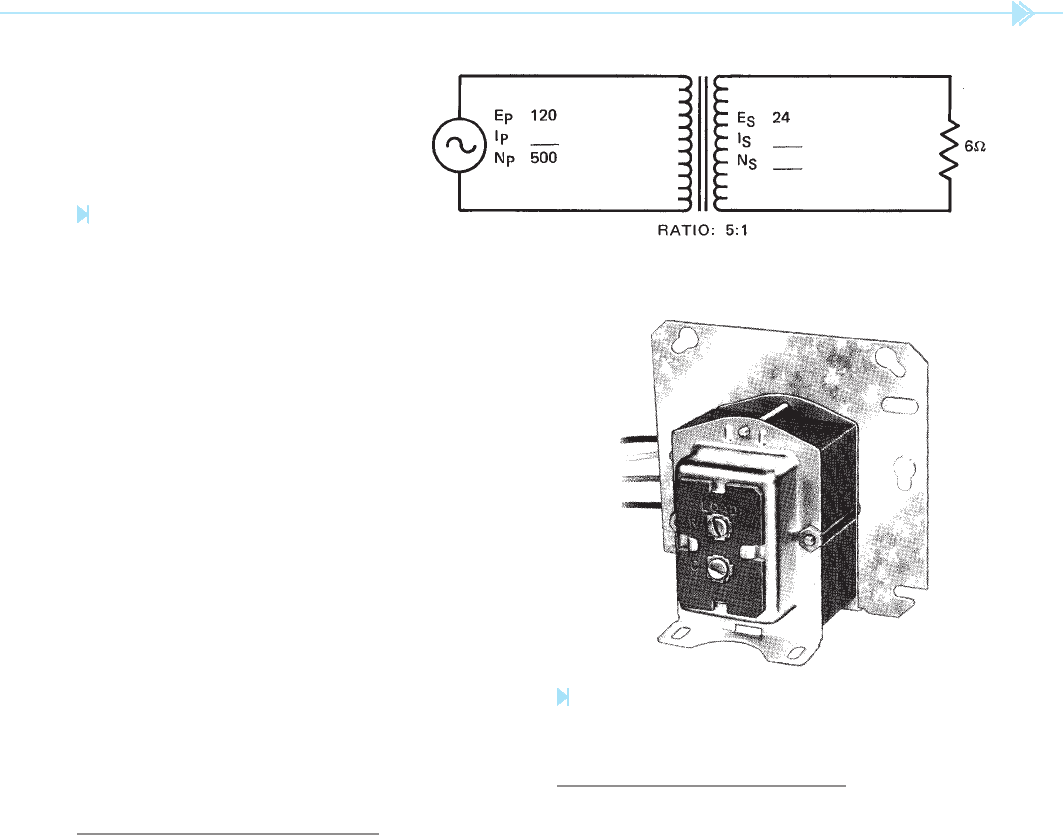
The transformer shown in Figure 25–4 is a step-
down transformer that has a primary voltage of
120 volts and a secondary voltage of 24 volts. The
secondary is connected to a load resistance of 6 ohms.
The current ow in the secondary winding is:
I ⫽
E
__
R
I ⫽
24
___
6
I ⫽ 4 amps
Now that the secondary current is known, the
amount of primary current can be computed.
E
p
__
E
S
⫽
I
S
__
I
p
120
____
24
⫽
4
__
I
p
120 I
p
⫽ 96
I
p
⫽.8 amp
If the amount of power for the primary and that for
the secondary are computed, it will be seen that they
are the same.
E
P
___
E
S
ⴝ
N
P
___
N
S
E
P
___
E
S
ⴝ
I
P
__
I
S
N
P
___
N
S
ⴝ
I
S
__
I
P
E
P
— Voltage of the primary
E
S
— Voltage of the secondary
N
P
— Number of turns of wire in the primary
N
S
— Number of turns of wire in the secondary
I
P
— Current fl ow in the primary
I
S
— Current fl ow in the secondary
Figure 25–3
Transformer formulas. (Source: Delmar/Cengage Learning)
UNIT 25 The Control Transformer 255
Figure 25–4
Step-down transformer. (Source: Delmar/Cengage Learning)
Primary
120 ⫻ .8 ⫽ 96
Secondary
24 ⫻ 4 ⫽ 96
The number of turns of wire in the secondary can
now be computed.
E
p
__
E
S
⫽
N
p
___
N
s
120
____
24
⫽
500
____
N
S
120 N
S
⫽ 12000
N
S
⫽ 100
Notice that the number of turns of wire in the sec-
ondary, 100, as compared with the turns of wire in
the primary, 500, is consistent with the turns ratio
of 5:1.
RESIDENTIAL CONTROL
TRANSFORMERS
Control transformers are used to change the
value of line voltage to the value needed for the
control circuit. Most residential air conditioning
systems operate on a control voltage of 24 volts
AC. The amount of current needed will vary from
one system to another, but it is generally less than
1 amp. The primary voltage for residential control
transformers is 120 or 240 volts. A photograph of a
control transformer used in residential applications
is shown in Figure 25–5. The primary lead wires
for most of these transformers will be black in color.
The color of the secondary leads will vary from one
manufacturer to another.
Figure 25–5
A 24-volt transformer. (Courtesy of Honeywell Inc.).
INDUSTRIAL CONTROL
TRANSFORMERS
Most industrial and commercial air conditioning
systems operate on 240 or 480 volts. The control
voltage for most of these units is 120 or 24 volts AC.
Most industrial control transformers contain two
primary windings and one or two secondary wind-
ings. In the following explanation, it will be assumed
that the transformer has two primary windings and
one secondary winding. In this type of transformer,
each primary winding has a voltage rating of
240 volts, and the secondary winding has a volt-
age rating of 120 volts. There is a turns ratio of
2:1 between each of the primary windings and the
secondary winding.
There is a standard for marking the terminals of
control transformers. One of the primary windings
256 SECTION 5 Control Components
240 VOLTS AC
H1
H2
H3
H4
X1
X2
120 VOLTS AC
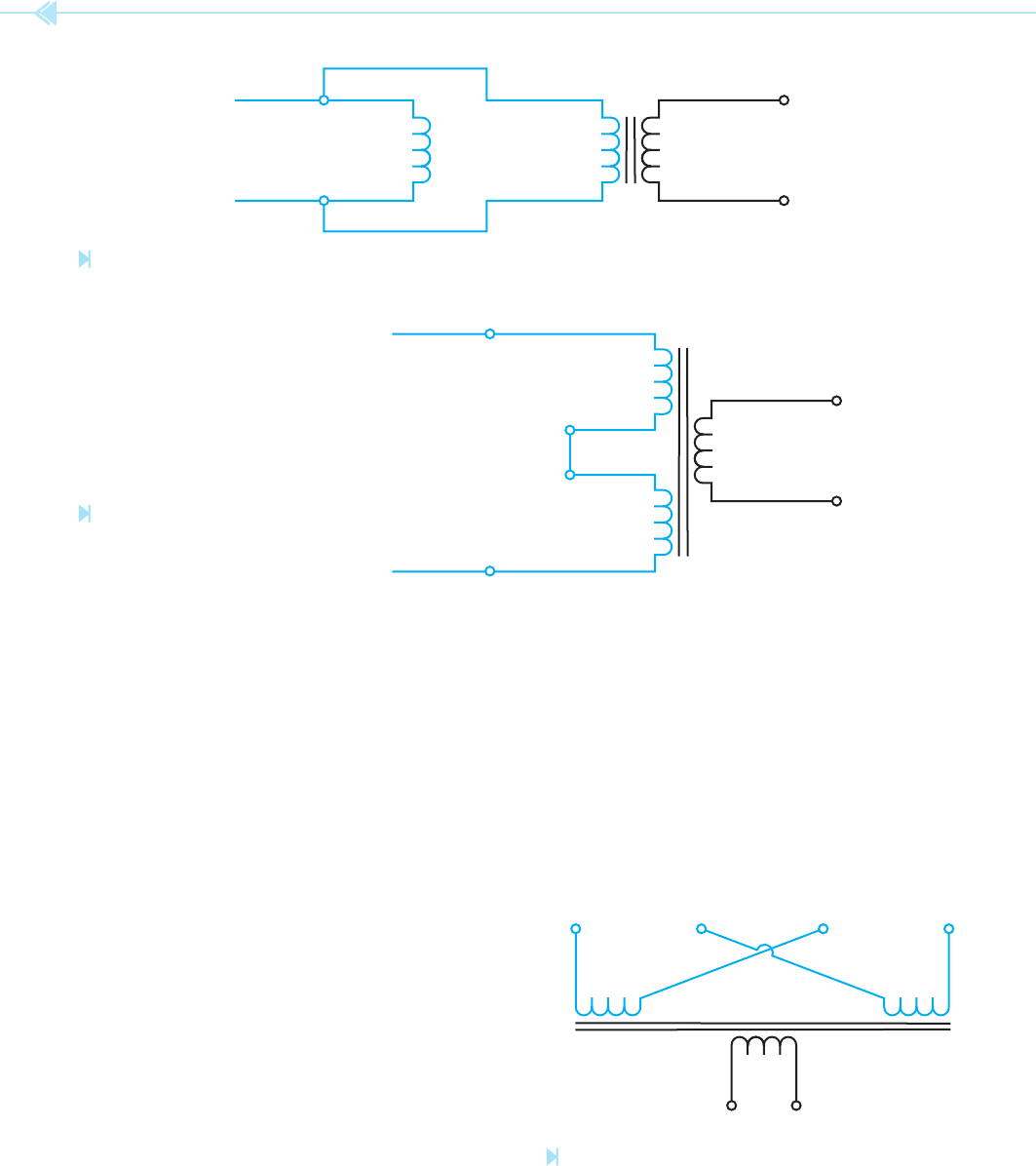
Figure 25–6
Primaries connected in parallel for 240-volt operation.
(Source: Delmar/Cengage Learning)
Figure 25–7
Primaries connected in series
for 480-volt operation.
(Source: Delmar/Cengage Learning)
480 VOLTS AC
H4
H1
H2
H3
X1
X2
120 VOLTS AC
X2X1
H3H4 H2 H1
will be identi ed with terminal markings of H1 and
H2. The other primary winding will be identi ed
with terminal markings of H3 and H4. The second-
ary winding will be identi ed with terminal mark-
ings of X1 and X2.
If the transformer is to be used to change a pri-
mary voltage of 240 volts into 120 volts, the two
primary windings will be connected in parallel as
shown in Figure 25–6. Because the two primary
windings are connected in parallel, each will receive
the same voltage. This will produce a turns ratio
of 2:1 between the primary windings and the sec-
ondary windings. If 240 volts is connected to the
primary of a 2:1 ratio transformer, the secondary
voltage will be 120 volts.
If the transformer is to be used to change 480 volts
to 120 volts, the primary windings will be connected
in series as shown in Figure 25–7. In this connection,
H2 of one primary winding is connected to H3 of the
other primary winding. This series connection of the
two windings produces a turns ratio of 4:1. When
480 volts is connected to the primary, 120 volts will
be produced in the secondary.
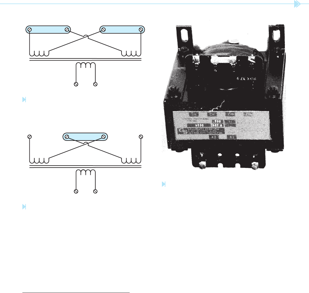
The primary windings of most control trans-
formers have leads H2 and H3 crossed as shown
in Figure 25–8. This is done to aid in the connec-
tion of the primary. For example, if it is desired to
operate the transformer with the primary wind-
ings connected in parallel, a metal link is used to
connect leads H1 and H3 together. Another metal
link is used to connect leads H2 and H4 together,
Figure 25–8
Primary leads are crossed. (Source: Delmar/Cengage Learning)
UNIT 25 The Control Transformer 257
Figure 25–9. Compare this lead connection with the
schematic shown in Figure 25–6.
If it is desired to connect the primary windings
for operation on 480 volts, terminals H2 and H3
are joined together with a metal link, Figure 25–10.
Compare this connection with the schematic shown
in Figure 25–7. A photograph of an industrial con-
trol transformer is shown in Figure 25–11.
TESTING THE TRANSFORMER
An ohmmeter is generally used to test the windings
of the transformer. To test the transformer, check
for continuity through each set of windings. For
example, there should be continuity between leads
H1 and H2; H3 and H4; and X1 and X2. There
should be no continuity between any of the wind-
ings such as H1 and H3, or H1 and X1. Also check
Figure 25–9
Metal links used to make a 240-volt connection.
(Source: Delmar/Cengage Learning)
Figure 25–11
Industrial control transformer. (Source: Delmar/Cengage Learning)
Figure 25–10
Metal link used to make a 480-volt connection.
(Source: Delmar/Cengage Learning)
X2
X1
H3H4 H2 H1
X2
X1
H3H2
for a grounded winding by testing to be sure there is
no continuity between any of the windings and the
case of the transformer.
The output voltage of the transformer should be
tested with an AC voltmeter. If the output voltage
is not close to the rated voltage, the transformer
is probably defective. If the transformer is tested
without a load connected to the secondary, it is nor-
mal for the secondary voltage to be slightly higher
than the rated voltage. For example, a 24-volt
transformer may have an output voltage as high
as 28 volts without load connected to it. The volt-
age rating of the transformer assumes it is supply-
ing full-rated current to the load. If the voltage is
tested when the transformer is under full load, the
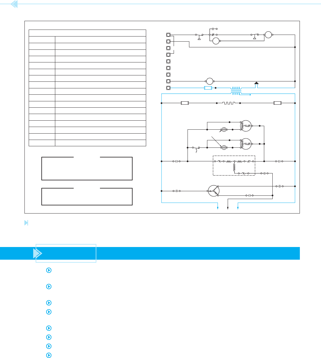
rated voltage should be seen. Notice the use of the
control transformer in the schematic shown in
Figure 25–12.
258 SECTION 5 Control Components
E1
T
Y2
Y1
W1
W2
W3
G
R
LPC
56 55
90
57
75 53
51
6
COIL
RR
RR
HPC
52 50
60
CC
61
68 BRN BRN
RED
BLU (208V TAP) SEE NOTE 7
30, 90
TRANSFORMER 208-230-24V
24V
LINE VOLTAGE
BLK
60
EFC
30A
92930
5A
10
5A
CCH
WHITE
RED DOT
OR ARROW
24
BRN
TOP
BLK 26
CFM-1
25
CAP-1
WHITE
34
BRN
TOP
BLK 36
CFM-2
354241
41
CC
111,9,4
31
CMT
CAP-2
OL
13 3,10,6
CC
L3OL
COMP
L1
L2
OL
CC
12 2.5
16 6,RED
EFC
15
87
5
EFC
4,BLK 14
TOP
88 86
EFC
LEGEND
CMT CONDENSER MOTOR THERMOSTAT
CAPACITOR
COMPRESSOR CONTACTOR
CRANKCASE HEATER
CONDENSER FAN MOTOR
COMPRESSOR
EVAPORATOR FAN CONTACTOR
FUSE
RESET RELAY
TRANSFORMER
TERMINAL BLOCK
TERMINAL OVERLOAD PROTECTOR
TERMINAL STRIP
EVAPORATOR FAN MOTOR
LOW PRESSURE CONTROL
HIGH PRESSURE CONTROL
OVERLOAD PROTECTOR
CAP
CC
CCH
CFM
COMP
EFC
F
RR
T
TB
TOP
TS
EFM
LPC
HPC
OL
WARINIG
DISCONNECT ELECTRICAL POWER
SOURCE TO PREVENT INJURY OR
DEATH FROM ELECTRICAL SHOCK
CAUTION
USE COPPER CONDUCTORS ONLY
TO PREVENT EQUIPMENT DAMAGE
Figure 25–12
Control transformer used to provide low voltage for the control circuit. (Schematic courtesy of Trane Corp.).
SUMMARY
A transformer is a device that can change values of AC voltage and current without a
change of frequency.
Isolation transformers have their primary and secondary sides physically and electrically
separated from each other.
Isolation transformers operate on the principle of mutual induction.
The primary is the winding of the transformer that is connected to the incoming
power line.
The secondary is the winding that is connected to the load.
All values of voltage and current in a transformer are proportional to the turns ratio.
A step-up transformer will have a higher secondary voltage than primary voltage.
A step-down transformer will have a lower secondary voltage than primary voltage.

UNIT 25 The Control Transformer 259
KEY TERMS
control transformers
isolation transformers
mutual induction
transformer
REVIEW QUESTIONS
1. What is an isolation transformer?
2. De ne a step-up transformer.
3. De ne a step-down transformer.
4. The primary of a transformer is connected to 120 volts AC. The secondary has a volt-
age of 30 volts and is connected to a resistance of 5 ohms. How much current will ow
in the primary of the transformer?
5. What is the amount of control voltage used in most residential air conditioning
systems?
6. What is the amount of control voltage used in most industrial air conditioning
systems?
7. What is the color of the primary leads of most control transformers used for residential
service?
8. How many primary windings are generally contained in an industrial control
transformer?
9. What is the turns ratio of each of these primary windings as compared with the
secondary winding?
10. When an industrial control transformer is to be operated on 480 volts, are the
primary windings connected in parallel or in series?