Stephen L. Herman, Bennie Sparkman. Electricity and Controls for HVAC-R (6th edition)
Подождите немного. Документ загружается.

280 SECTION 5 Control Components
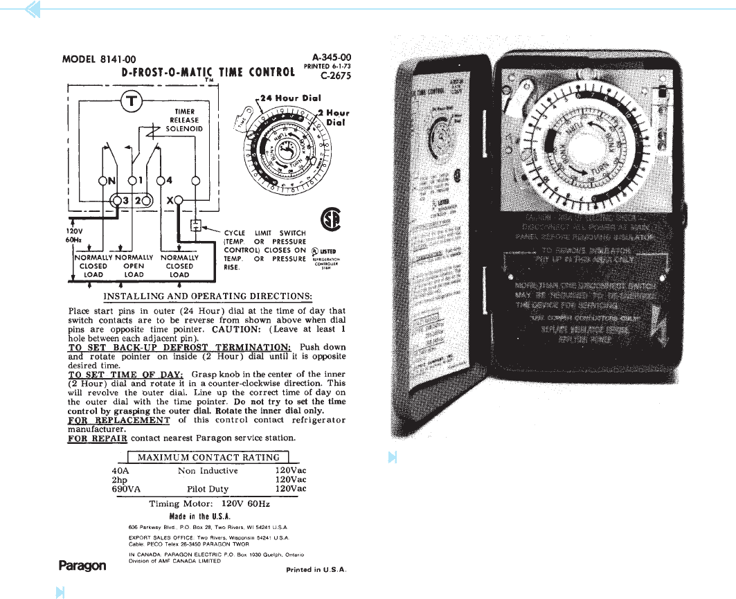
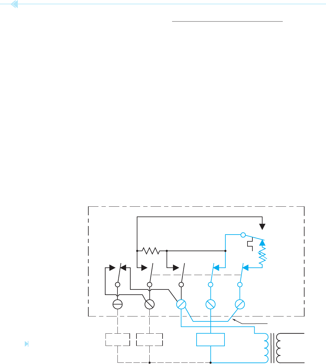
Figure 28–9
Schematic diagram of a commercial defrost timer.
(Courtesy of Paragon Electric Company, Inc.).
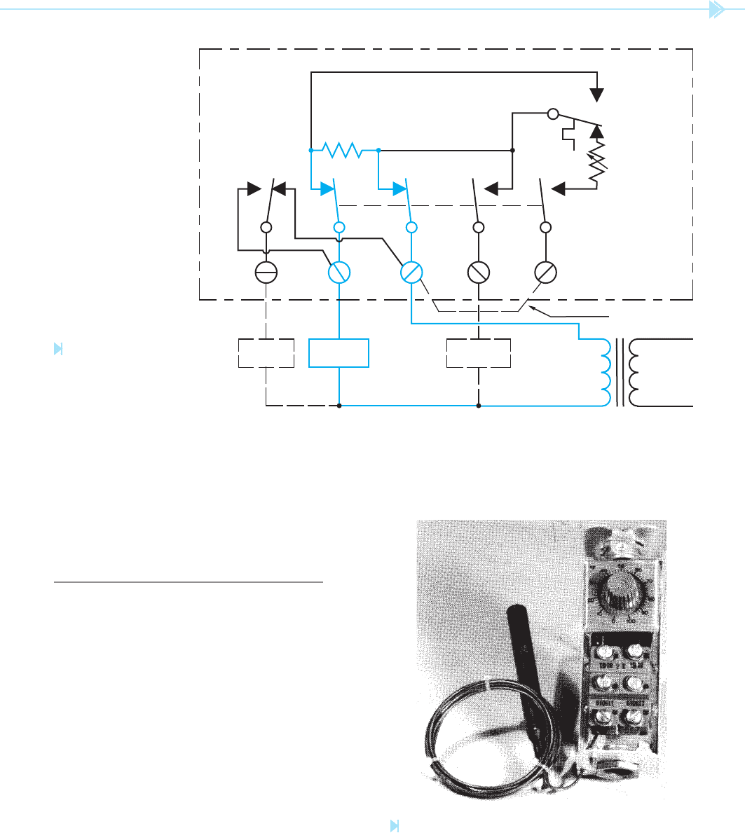
Figure 28–10
Commercial defrost timer. (Courtesy of Paragon Electric Company, Inc.).

UNIT 28 The Defrost Timer 281
SUMMARY
Frost-free appliances use a defrost timer to control the operation of the defrost cycle.
The function of the defrost timer is to disconnect the compressor from the circuit and
connect a resistive heater located near the evaporator at regular intervals.
The defrost timer is a cam-operated timer powered by a small single-phase synchronous
motor similar to an electric clock motor.
Two basic connections for a defrost timer are:
A. The continuous run timer.
B. The cumulative compressor run timer.
The motor of the continuous run timer is connected directly to the power line and runs at
all times.
The motor of the cumulative compressor run timer is connected in such a manner that it
runs only during the time the compressor motor is in operation.
Commercial defrost timers often use a separate time clock to control the defrost cycle.
KEY TERMS
cam
continuous run timer
cumulative compressor
run timer
defrost timer
evaporator
resistive heating element
timer clock
REVIEW
QUESTIONS
1. What type of motor is used to operate the timer?
2. Why is one of the motor leads brought outside the timer?
3. Name two ways of connecting the defrost timer.
4. What function does the defrost heater perform?
5. To which terminal is the pigtail lead of the timer motor connected if the timer is to
operate continuously?

Thermostats are temperature-sensitive switches.
They use a variety of methods to sense temperature,
and can be found with different
contact arrange-
ments. Some thermostats are designed to be used
with low-voltage systems, generally 24 volts; and
others are designed to be connected directly to line
voltage and operate motors and heating units. The
advantage of low-voltage thermostats is that they
are more economical and safer to use inside the
home.
BIMETAL THERMOSTATS
One of the most common methods of sensing tem-
perature is with a bimetal strip. When used as
the temperature sensing element of a thermostat,
the bimetal strip is generally bent in a spiral that
282
OBJECTIVES
After studying this unit the student should
be able to:
Defi ne a thermostat
Describe the operation of bimetal
thermostats
Discuss the operation of a contact-type
and mercury-contact thermostat
Discuss the operation of heating and
cooling thermostats
Describe the operation of the fan
switch
Discuss the operation of the heat
anticipator and cooling anticipator
Discuss the operation of line voltage,
programmable, staging, and
differential thermostats
Connect a thermostat in a circuit
UNIT 29
The
Thermostat
UNIT 29 The Thermostat 283
MERCURY CONTACT
THERMOSTAT
Another type of contact used with the bimetal type
of thermostat is the mercury contact. In this type of
thermostat, a small pool of mercury is sealed inside
resembles a clock spring. If a contact is attached
to the end of the strip and another contact is held
stationary, a thermostat is formed, Figure 29–1. A
small permanent magnet is used to provide a snap
action for the contacts.
This type of thermostat is inexpensive and has
the advantage of not having to be mounted in
a level position. The greatest enemy of an open-
contact thermostat is dirt. This is especially true for
thermostats designed for low-voltage operation. If
poor thermostat contact is suspected, the contacts
should be cleaned. This can be done with a strip
of hard paper, such as typing paper, and alcohol.
Soak a strip of hard paper in alcohol and place the
strip between the contacts. Close the contacts and
draw the strip through the closed contacts. This
will generally remove any accumulation of dirt and
oil. After cleaning, the contacts should be buffed to
remove any alcohol residue. This can be done by
drawing a piece of dry hard paper through the con-
tacts several times. This type of thermostat is shown
in Figure 29–2.
To avoid the problem of dirty contacts, the con-
tacts of some thermostats are enclosed inside a
glass tube, Figure 29–3. Because the contacts are
enclosed in glass, they are stationary. The bimetal
strip is attached to a permanent magnet instead of
a contact. In the case of a double acting thermostat,
there are two magnets attached to the bimetal strip.
When the magnet is close enough to the glass tube,
it is attracted to the metal contacts and causes the
contacts to close with a snap action.
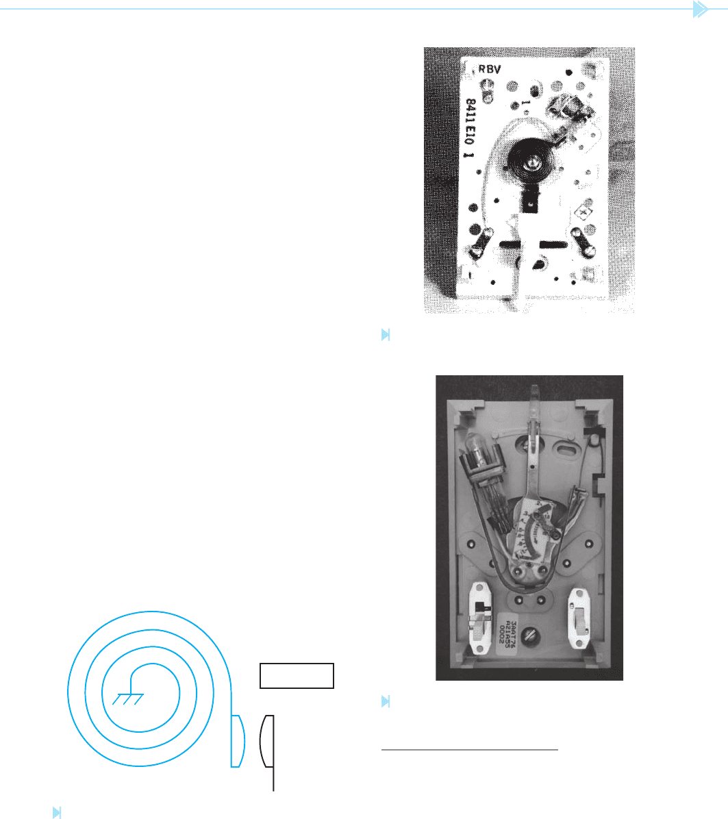
MAGNET
Figure 29–1
Contacts operated by a bimetal strip. (Source: Delmar/Cengage
Learning)
Figure 29–2
Open-contact thermostat. (Source: Delmar/Cengage Learning)
Figure 29–3
Contacts are enclosed inside a glass tube.
(Source: Delmar/Cengage Learning)
284 SECTION 5 Control Components
can sometimes be a problem in homes that do not
remain level. A mercury type thermostat is shown
in Figure 29–6.
Mercury type thermostats are particularly sen-
sitive to the way they are mounted. If they are to
operate correctly, they must be mounted level. The
manufacturer’s instructions will generally show
how the thermostat should be checked with a level-
ing device.
HEATING AND COOLING
THERMOSTATS
Many thermostats are designed to be used for both
heating and cooling applications. This can be done
with thermostats that contain both a normally
open and normally closed contact. A simple sche-
matic diagram of this type of thermostat is shown
in Figure 29–7. Notice the thermostat contact is a
single-pole double-throw type. The selector switch
is a double-pole type. The dashed line indicates
mechanical intertie. With the selector switch in
the position shown, the thermostat is being used
for heating. If the selector switch is changed, the
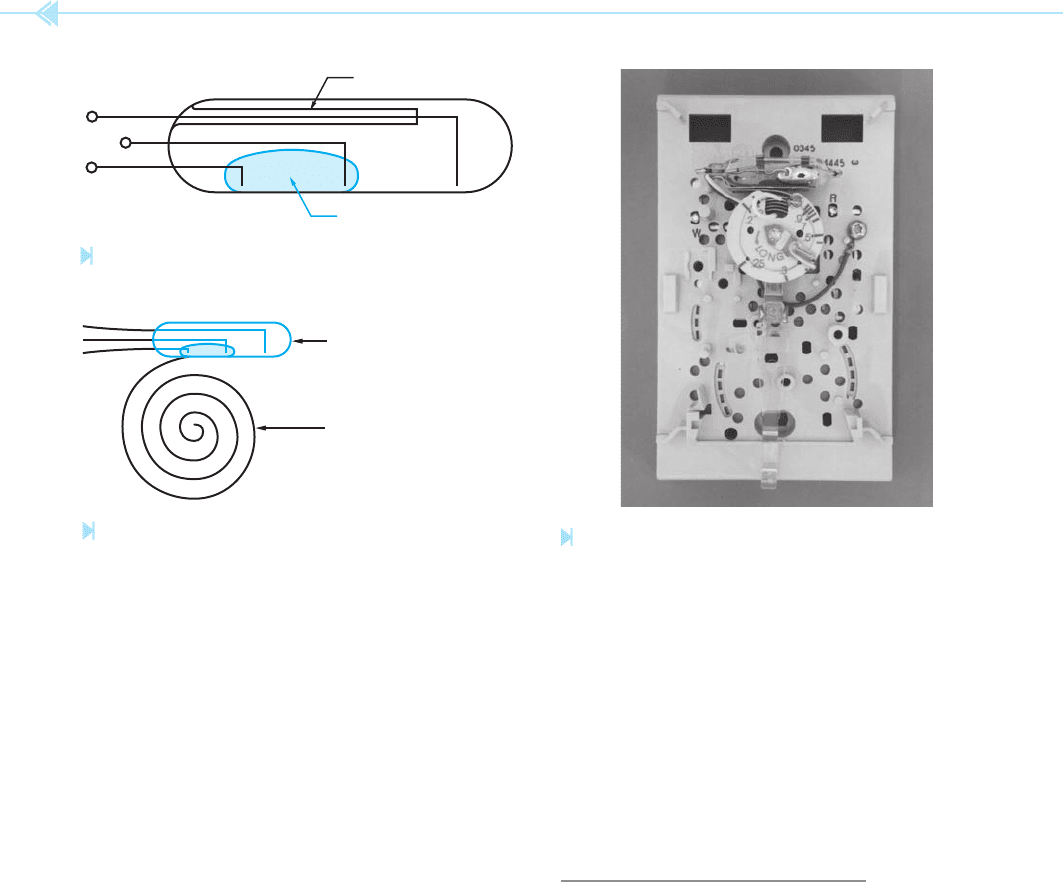
a glass container. A set of contacts is also sealed in
the glass. Most mercury-type contacts are made to be
single-pole double-throw, which means there are a
common terminal, a normally open terminal, and
a normally closed terminal. Figure 29–4 illustrates
this type of contact. Notice in this example that the
pool of mercury makes connection with the com-
mon terminal, located in the center, and the nor-
mally closed terminal. If the glass bulb is tilted in the
other direction, the mercury will ow to the opposite
end and make connection between the common ter-
minal and the normally open contact.
The mercury contact has the advantage of
being sealed in glass and not subjected to dirt
and oil. When this type of contact is used with a
bimetal strip, it is generally mounted as shown in
Figure 29–5. This type of thermostat uses the weight
of the mercury to provide a snap action for the con-
tact instead of a magnet. When the bimetal strip
has turned far enough to permit the mercury to
ow from one end of the glass bulb to the other, the
weight of the mercury prevents any spring action of
the bimetal strip from snapping the contact open.
A mercury thermostat, however, must be mounted
in a level position if it is to operate properly. This
NO
INSULATOR
MERCURY
NC
C
Figure 29–4
Mercury contacts. (Source: Delmar/Cengage Learning)
MERCURY CONTACTS
BIMETAL STRIP
Figure 29–5
Mercury-type thermostat. (Source: Delmar/Cengage Learning)
Figure 29–6
Mercury thermostat. (Source: Delmar/Cengage Learning)
UNIT 29 The Thermostat 285
controlled by the thermostat. If the switch is thrown
in the opposite direction, the fan relay is connected
directly to the control voltage.
THE HEAT ANTICIPATOR
The heat anticipator is a small resistance heater
located near the bimetal strip. The function of
this heater is to slightly preheat the bimetal strip
and prevent overrun of the heating system. For
example, many heating systems, such as fuel oil or
gas, operate by heating a metal container called a
heat exchanger. When the temperature of the heat
exchanger reaches a high enough level, a thermo-
statically controlled switch causes the blower to
turn on and blow air across the heat exchanger. The
moving air causes heat to be removed from the heat
exchanger to the living area. When the thermostat
is satis ed, the heating unit is turned off. The blower
will continue to operate, however, until the excess
heat has been removed from the heat exchanger.
Now assume that the thermostat has been set
for a temperature of 75 degrees. If the heating
unit is permitted to operate until the temperature
reaches 75 degrees, the nal temperature of the
living area may be from 3 to 5 degrees higher than
bottom movable contact will break connection with
its stationary contact, and the top movable contact
will make connection with its stationary contact.
Notice that changing this switch will also change
the sense of the thermostat. In the heating position,
the thermostat activates the heating unit when the
contact closes because of a decrease in temperature.
In the cooling position, the thermostat activates the
air conditioning unit when the contact makes con-
nection because of an increase in temperature.
THE FAN SWITCH
Many thermostats are designed to permit manual
control of the blower fan. This is done to permit the
blower fan to be operated separately. Some people
nd it desirable to operate the blower fan con-
tinuously to provide circulation of air throughout
the building. This is especially true for buildings
equipped with electronic air cleaners (precipitators)
or for buildings that must remove undesirable ele-
ments such as smoke in an of ce building or night
club. A schematic diagram of this type of circuit
is shown in Figure 29–8. The fan switch is a
single-pole double-throw switch. When the switch
is in one position, it permits the fan relay to be
THERMOSTAT
R
COOL
TO AIR-CONDITIONING
CONTR
OL UNIT
HEAT
TO HEATING
CONTR
OL UNIT
SELECTOR
SWITCH
Figure 29–7
Dual operation of a thermostat.
(Source: Delmar/Cengage Learning)
TO THERMOSTAT AUTO
FAN SWITCH
FAN RELAY COIL
MAN
Y
NEUTRAL
FR
G
Figure 29–8
Fan switch. (Source: Delmar/
Cengage Learning)
286 SECTION 5 Control Components
THE COOLING ANTICIPATOR
A device that operates in a similar manner to the
heat anticipator is the cooling anticipator.
The cooling anticipator is a resistive heating ele-
ment that operates in an opposite sense to the heat
anticipator. The cooling anticipator operates while
the thermostat contacts are open and the air con-
ditioning unit is not running. The cooling anticipa-
tor heats the thermostat slightly and causes it to
close its contacts before the ambient temperature
increases enough to close them.
The circuit shown in Figure 29–9 displays the
current path of the heat anticipator for a heating
and cooling thermostat during the heating cycle.
In this mode of operation, current ows through
the heat anticipator while the thermostat contact is
closed and the heating unit is in operation.
In Figure 29–10, the thermostat has been
switched to the cooling mode. Notice that a current
path exists through the cooling anticipator when
the thermostat setting by the time enough heat has
been removed from the heat exchanger to cause the
blower to turn off.
If the heat anticipator has been properly set,
however, it will cause the thermostat to turn off
several degrees before the room temperature has
reached the thermostat setting. This permits the
excess heat of the heat exchanger to raise the tem-
perature to the desired level without overrunning
the thermostat setting.
The setting of the heat anticipator is controlled
by a sliding contact. There are markings such as .2,
.25, .3, .35, and .4. The sliding contact is generally
set at the number that corresponds to the current
rating of the control system. The current rating can
generally be located in the service information or on
the control unit itself. The heat anticipator does not
have to be set at that position, however. The service
technician should set it to operate the unit for longer
or shorter periods depending on the desires of the
customer.
JUMPER
TRANS-
FORMER
COOL
HEAT
HEAT
ANTICIPATOR
COOLING
ANTICIPATOR
FAN
AUTO ON
FAN
RELAY
COOLING
SYSTEM
HEATING
SYSTEM
Figure 29–9
Current path for heat
anticipator.
(Source:
Delmar/Cengage Learning)
UNIT 29 The Thermostat 287
the thermostat contact is open and the air condi-
tioning unit is not in operation. When the ther-
mostat contact closes, a low resistance path exists
around the cooling anticipator. This stops the ow
of current through it while the air conditioning unit
is in operation.
LINE VOLTAGE THERMOSTATS
Line voltage thermostats are generally used
to control loads such as blower fans and heating
elements. This means that the thermostat must
contain contacts that are capable of handling the
current needed to operate these loads without
an intervening relay. This type of thermostat is
shown in Figure 29–11. Many of these thermo-
stats use the pressure of refrigerant in a sealed
system to sense temperature, Figure 29–12. When
the temperature increases, the pressure in the
system increases also. The increase in pressure
causes the bellows to expand. When the bellows
expands far enough, it activates a set of spring-
loaded contacts.
JUMPER
TRANS-
FORMER
COOL
HEAT
HEAT
ANTICIPATOR
COOLING
ANTICIPATOR
FAN
AUTO ON
FAN
RELAY
COOLING
SYSTEM
HEATING
SYSTEM
Figure 29–10
Current path for
cooling anticipator.
(Source: Delmar/Cengage
Learning)
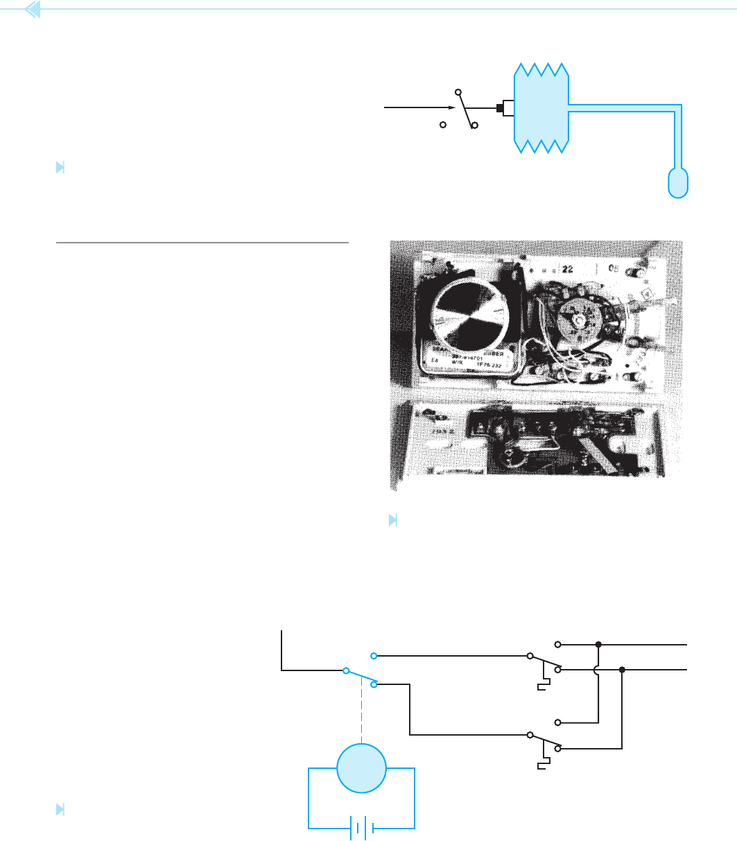
Figure 29–11
Line voltage thermostat. (Source: Delmar/Cengage Learning)
Although line voltage thermostats can be used
for many applications, they do not contain a heat
anticipator and are not as accurate as low voltage
thermostats.
288 SECTION 5 Control Components
PROGRAMMABLE THERMOSTATS
The term programmable is a catch word that has
taken on many meanings. In the case of ther-
mostats, the term programmable generally means
that a thermostat can be set to operate at different
temperature settings at different times.
Program-
mable thermostats range in complexity from
units that use a simple time clock to units that are
operated by integrated circuits (ICS) and permit the
temperature to be set to any desired level at any
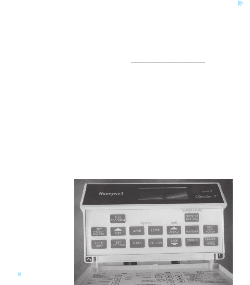
desired time. A programmable thermostat is shown
in Figure 29–13. This thermostat uses a quartz-
operated time clock and two separate thermostat
units. The time clock is used to operate a switch. The
setting of the clock determines the position of the
switch at any particular time. A schematic for this
type of circuit is shown in Figure 29–14. Notice that
SPRING-LOADED
CONTACTS
BELLOWS
Figure 29–12
Thermostat contacts are operated by
pressure. (Source: Delmar/Cengage Learning)
Figure 29–13
Programmable thermostat. (Source: Delmar/Cengage Learning)
THERMOSTAT B
THERMOSTAT A
TO CONTROL
CIRCUIT
R
+–
CLOCK
Figure 29–14
Schematic for a programmable
thermostat. (Source: Delmar/Cengage Learning)
UNIT 29 The Thermostat 289
for several different conditions or events. Many per-
mit the thermostat to be programmed differently for
each day. The temperature can be set differently for
different times of the day. Most electronic thermo-
stats provide a variety of functions and options that
are set by the homeowner. An electronic thermostat
is shown in Figure 29–15.
STAGING THERMOSTATS
Staging thermostats are similar to program-
mable thermostats in that they contain two separate
sets of contacts. Unlike the programmable ther-
mostat, however, the staging thermostat contains
only one bimetal strip, which is used to control the
action of both sets of contacts. One set of contacts
is designed to operate slightly behind the other set.
A good example of how a staging thermostat is used
can be found in a heat-pump system. Assume that
the rst contact is used to operate the compressor
relay, and the second contact is used to operate the
contactor, which controls the electric resistance
heating strips. When the temperature decreases,
the rst thermostat contact closes and connects the
compressor to the line. If the compressor is able to
provide enough heat to the dwelling, the second
contact will never make connection. If, however,
the position of the clock-operated switch determines
which thermostat is used to control the system.
To understand the operation of this system, assume
that thermostat A has been set for a temperature of
95 degrees, and thermostat B is set for 75 degrees.
The time clock has been set to permit thermostat A
to control the air conditioning system when there is
no one in the residence. One hour before people are
to return home, the time clock changes the contact
and thermostat B is used to control the system.
Because thermostat B has been set for 75 degrees,
the residence will have been cooled to that tempera-
ture when the people arrive.
The programmable thermostat can reduce energy
consumption by maintaining a desired temperature
only during the hours the dwelling is occupied. The
temperature can be maintained at an uncomfort-
able level the rest of the time, which permits the air
conditioning unit to operate much less.
Electronic Programmable
Thermostats
Many programmable thermostats are solid state and
do not contain mechanical contacts. These units
generally employ electronic devices such as thermis-
tors to sense temperature. They can be programmed
Figure 29–15
Electronic thermostat.
(Source: Delmar/Cengage Learning)