Stephen L. Herman, Bennie Sparkman. Electricity and Controls for HVAC-R (6th edition)
Подождите немного. Документ загружается.


270
The use of small variable-speed motors has
increased greatly in the last few years. These motors
are commonly used to operate light loads such as
ceiling fans and blower motors. There are two types
of motors used for these applications, the shaded-
pole and the permanent-split capacitor motor.
These motors are used because they operate with-
out having to disconnect a set of start windings
with a centrifugal switch or starting relay. Motors
intended to be used in this manner are wound with
high-impedance stator windings. The high imped-
ance of the stator limits the current ow through
the motor when the speed of the rotor is decreased.
Speed control for these motors is accomplished by
controlling the amount of voltage applied to the
motor, or by inserting impedance in series with the
stator winding.
OBJECTIVES
After studying this unit the student should
be able to:
Describe different types of variable-
speed motors
Discuss autotransformer control
Connect an autotransformer speed
controller in a circuit
Discuss the use of a triac to control
motor speed
Connect a triac speed controller in
a circuit
Discuss the operation of a series
impedance speed control
Connect a series impedance speed
controller in a circuit
Variable-
Speed Motor
Control
UNIT 27
UNIT 27 Variable-Speed Motor Control 271
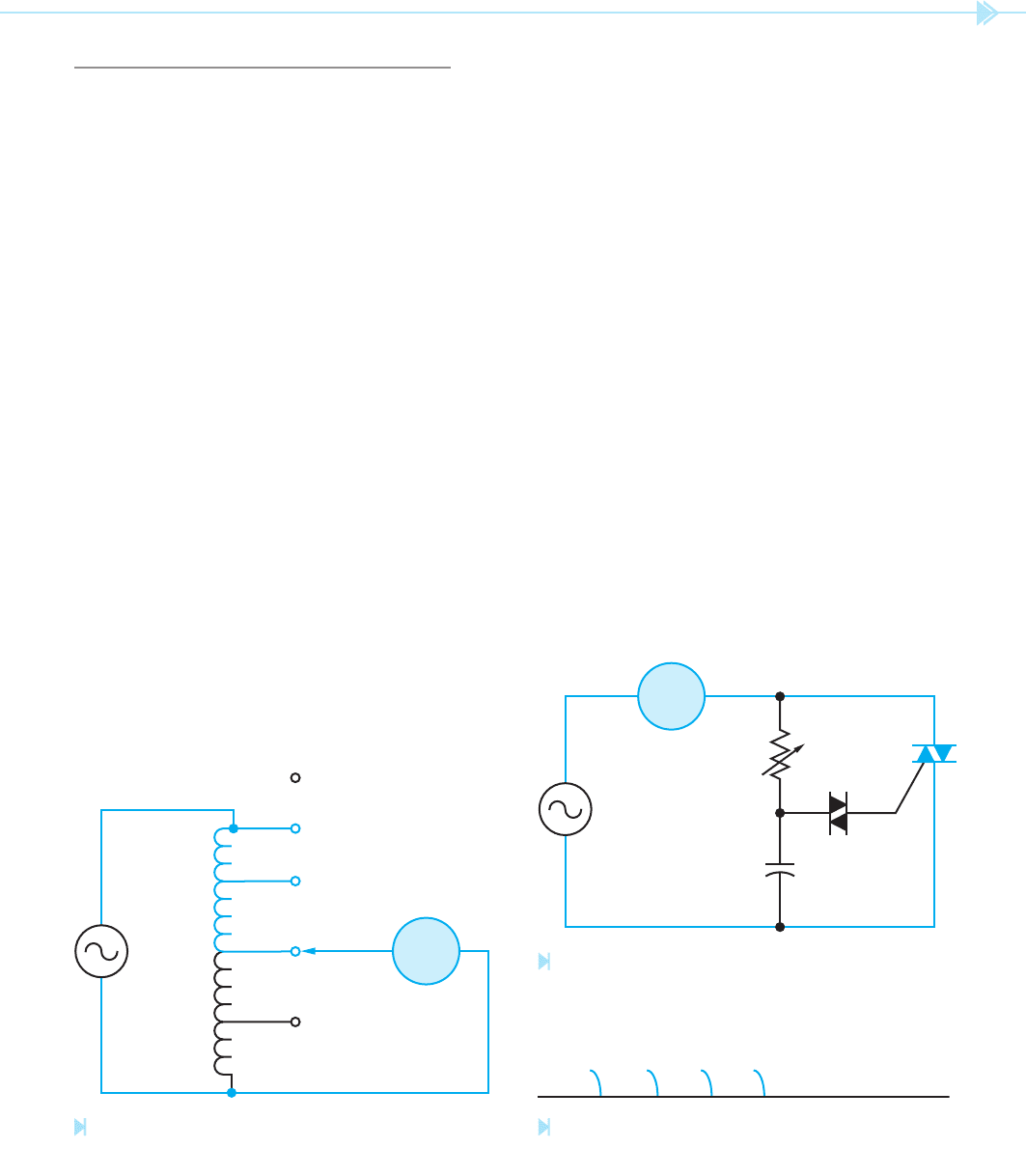
VARIABLE-VOLTAGE CONTROL
The amount of voltage applied to the motor can
be controlled by several methods. One method is
to use an autotransformer with several taps,
Figure 27–1. This type of controller has several steps
of speed control. Notice that the applied voltage,
120 volts in this illustration, is connected across
the entire transformer winding. When the rotary
switch is moved to the rst tap, 30 volts is applied
to the motor. This produces the lowest motor speed
for this controller. When the rotary switch is moved
to the second tap, 60 volts is applied to the motor.
This provides an increase in motor speed. When the
switch has been moved to the last position, the full
120 volts is applied to the motor operating it at the
highest speed.
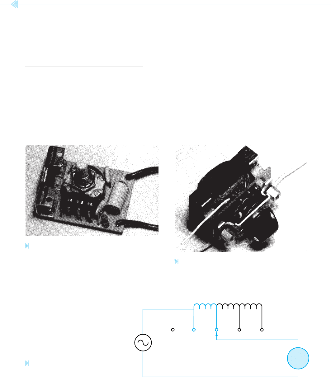
Another type of variable-voltage control uses
a triac to control the amount of voltage applied to
the motor, Figure 27–2. This type of speed control
provides a more linear control since the voltage can
be adjusted from 0 to the full applied voltage. At
rst appearance, many people assume this control-
ler to be a
variable resistor connected in series
with the motor. A variable resistor large enough to
control even a small motor would produce several
hundred watts of heat and could never be mounted
in a switch box. The variable resistor in this circuit
is used to control the amount of phase shift for
the triac. The triac controls the amount of voltage
applied to the motor by turning on at different times
during the AC cycle.
A triac speed control is very similar to a triac light
dimmer used in many homes. A light dimmer, how-
ever, should never be used as a motor speed control-
ler. Triac light dimmers are intended to be used with
resistive loads such as incandescent lamps. Light
dimmer circuits will sometimes permit one half of
the triac to start conducting before the other half.
The wave form shown in Figure 27–3 illustrates
this condition. Notice that only part of the positive
half of the waveform is being conducted to the load.
Since only positive voltage is being applied to the
load, it is DC. Operating a resistive load, such as
an incandescent lamp with DC, will do no damage.
Operating an inductive load such as the winding of
a motor can do a great deal of damage, however.
When direct current is applied to a motor winding,
there is no inductive reactance to limit the current.
The actual wire resistance of the stator is the only
current limiting factor. The motor winding or the
30 VOLTS
60 VOLTS
90 VOLTS
120 VOLTS
OFF
MOTOR
Figure 27–1
Autotransformer controls motor voltage. (Source: Delmar/
Cengage Learning)
MOTOR
Figure 27–2
Triac used to control motor speed.
(Source: Delmar/Cengage Learning)
Figure 27–3
Triac conducts only the positive half of the waveform.
(Source: Delmar/Cengage Learning)
272 SECTION 5 Control Components
Figure 27–5
Series inductor changes impedance of
circuit. (Source: Delmar/Cengage Learning)
OFF
MOTOR
1ST 2ND 3RD 4TH
controller can easily be destroyed if direct current is
applied to the motor. For this reason only triac con-
trollers designed for use with inductive loads should
be used for motor control. A photograph of a triac
speed controller is shown in Figure 27–4.
SERIES IMPEDANCE CONTROL
Another common method of controlling the speed
of small AC motors is to connect impedance in series
with the stator winding. This is the same basic
method of control used with multi-speed fan motors.
The circuit in Figure 27–5 shows a tapped inductor
connected in series with the motor. When the motor
is rst started, it is connected directly to the full
voltage of the circuit. As the rotary switch is moved
from one position to another, steps of inductance
are connected in series with the motor. As more
inductance is connected in series with the stator,
the amount of current ow decreases. This produces
a weaker magnetic eld in the stator.
Rotor slip
increases because of the weaker magnetic eld
and
causes the motor speed to decrease. A photograph of
this type of controller is shown in Figure 27–6.
Figure 27–4
Triac speed control. (Source: Delmar/Cengage Learning)
Figure 27–6
Fan speed control using a tapped inductor connected in
series with the motor. (Source: Delmar/Cengage Learning)

UNIT 27 Variable-Speed Motor Control 273
SUMMARY
The two main types of single-phase AC motors used for variable-speed control are the
permanent-split capacitor motor and the shaded-pole motor.
Permanent-split capacitor motors and shaded-pole motors are generally used for variable-
speed control because they do not have to disconnect the start windings when the motor
reaches a certain speed.
Variable-speed control for small motors is accomplished by controlling the amount of
voltage applied to the motor or by inserting impedance in series with the motor.
Two common methods used to control the voltage applied to the motor are autotrans-
former control and triac control.
Only triac controllers designed for use as motor speed controllers should be used for motor
speed control.
Series impedance control is accomplished by connecting a tapped inductor in series with
the motor.
KEY TERMS
autotransformer
rotor slip
variable resistor
variable-speed motors
REVIEW QUESTIONS
1. What two types of small AC motors are used with variable-voltage speed control?
2. Why are these two types of motors used?
3. Name two methods of variable-voltage control for small AC motors.
4. What solid-state device is used to control the voltage applied to the motor?
5. Why is it necessary to use only controllers designed for use with inductive loads?
6. Name a method other than variable voltage used to control the speed of small
AC motors.

274
Many of the refrigeration appliances used in the
home are “frost-free.” The frost-free appliance could
more accurately be termed “automatic defrost.”
The brain of the frost-free appliance is the defrost
timer. The job of this timer is to disconnect the
compressor circuit and connect a resistive heat-
ing element located near the evaporator at
regular time intervals. The defrost heater is ther-
mostatically controlled and is used to melt any frost
formation on the evaporator. The defrost heater is
permitted to operate for some length of time before
the timer disconnects it from the circuit and permits
the compressor to operate again.
TIMER CONSTRUCTION
The defrost timer is operated by a single-phase syn-
chronous motor like those used to operate electric
wall clocks, Figure 28–1. The contacts are operated
OBJECTIVES
After studying this unit the student should
be able to:
Describe the construction of a
defrost timer
Discuss the operation of a continuous
run and cumulative compressor
run timer
Connect a defrost timer for
continuous run
Connect a defrost timer for cumulative
compressor run
Discuss the operation of commercial
defrost timers
Perform an ohmmeter test on a
defrost timer
The Defrost
Timer
UNIT 28
UNIT 28 The Defrost Timer 275
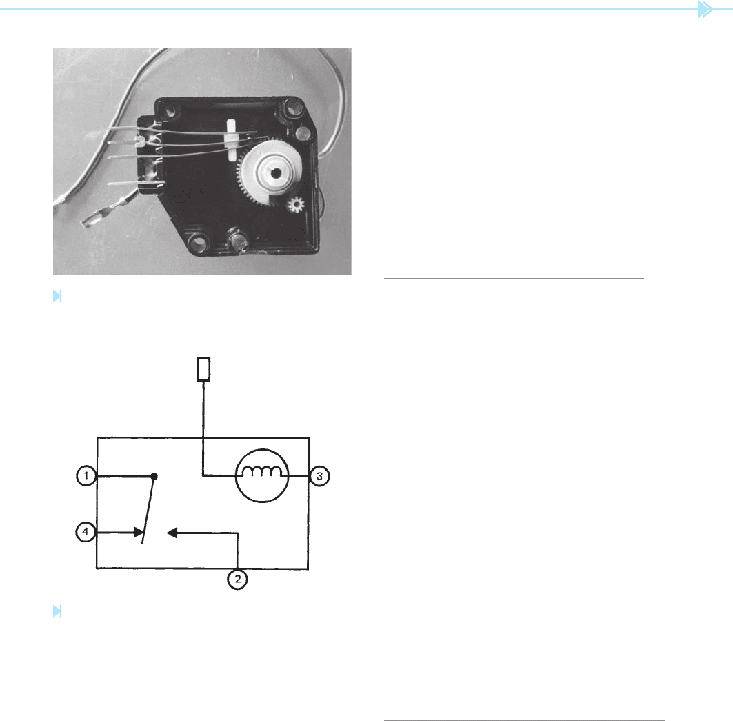
brought outside the case. This permits the timer to
be connected in one of two ways, which are:
1. The continuous run timer.
2. The cumulative compressor run timer.
It should be noted that the schematic draw-
ing can be a little misleading. In the schematic
shown, the timer contact can only make connection
between terminals 1 and 4, or terminals 1 and 2. In
actual practice, a common problem with this timer
is that the movable contact becomes stuck between
terminals 4 and 2. This causes the compressor and
defrost heater to operate at the same time.
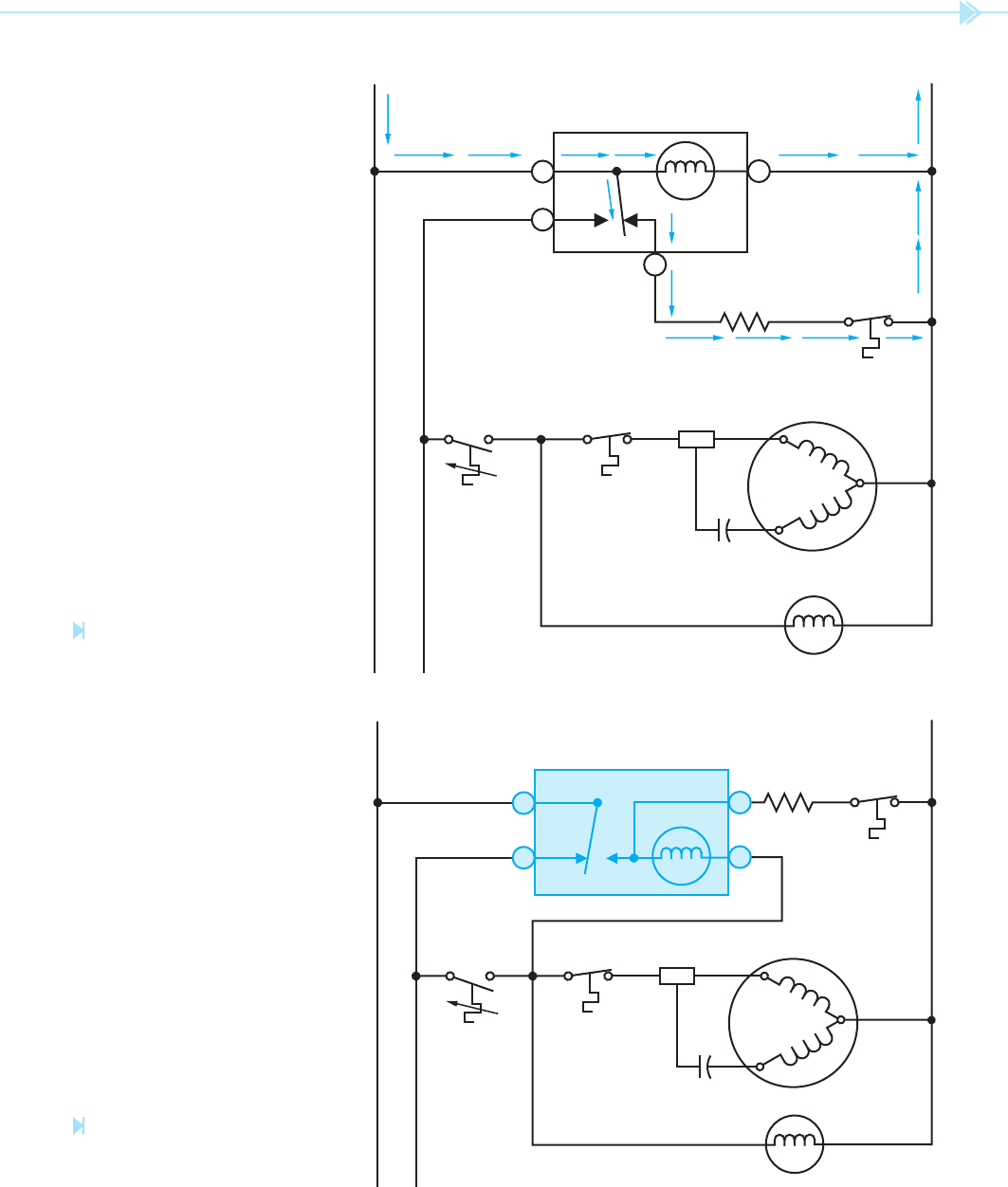
THE CONTINUOUS RUN TIMER
The schematic for the continuous run timer is
shown in Figure 28–3. Notice in this circuit that the
pigtail lead of the motor has been connected to ter-
minal 1, and that terminal 1 is connected directly to
the power source. Terminal 3 is connected directly
to the neutral. This places the timer motor directly
across the power source, which permits the motor to
operate on a continuous basis.
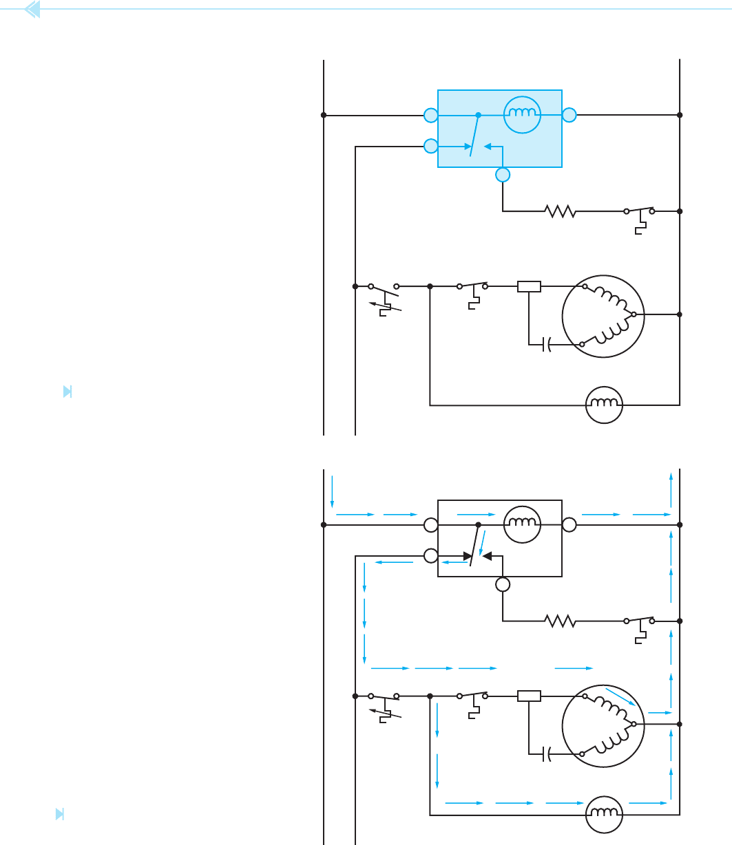
Figure 28–4 shows the operation of the timer in
the compressor run cycle. Notice there is a current
path through the timer motor and a path through
the timer contact to the thermostat. This permits
power to be applied to the compressor and evapora-
tor motor when the thermostat closes.
Figure 28–5 shows the operation of the circuit
when the timer changes the contact and activates the
defrost cycle. Notice there is still a complete circuit
through the timer motor. When the timer contact
changes position, the circuit to the thermostat is open
and the circuit to the defrost heater is closed. The
heater can now melt any frost accumulation on the
evaporator. At the end of the defrost cycle, the timer
contact returns to its normal position and permits the
compressor to be operated by the thermostat.
THE CUMULATIVE COMPRESSOR
RUN TIMER
The cumulative compressor run timer circuit gets its
name from the fact that the timer motor is permitted
to operate only when the compressor is in operation
and the thermostat is closed. The schematic for this
circuit is shown in Figure 28–6. Notice that the
by a cam that is gear driven by the clock motor.
A schematic drawing of the timer is shown in
Figure 28–2. Notice that terminal 1 is connected to
the common of a single-pole double-throw switch.
Terminals 2 and 4 are connected to stationary con-
tacts of the switch. In the normal operating mode,
the switch makes connection between contacts
1 and 4. When the defrost cycle is activated, the
contact will change position and make connection
between terminals 1 and 2. Terminal 3 is connected
to one lead of the motor. The other motor lead is
Figure 28–1
Defrost timer. (Source: Delmar/Cengage Learning)
Figure 28–2
Schematic of a defrost timer. (Source: Delmar/Cengage Learning)
276 SECTION 5 Control Components
H N
R
S
C
COMPRESSOR
START
RELAY
EVAPORATOR FAN
DEFROST
THERMOSTAT
OVERLOAD
THERMOSTAT
TIMER
120 VAC 60 Hz
DEFR
OST
HEATER
1
4
3
2
H N
R
S
C
COMPRESSOR
START
RELAY
EVAPORATOR FAN
DEFROST
THERMOSTAT
OVERLOAD
THERMOSTAT
TIMER
120 VAC 60 Hz
DEFROST
HEATER
1
4
3
2
Figure 28–3
Schematic of a defrost timer used in a
continuous run circuit.
(Source: Delmar/Cengage Learning)
Figure 28–4
Current path during cooling operation.
(Source: Delmar/Cengage Learning)
UNIT 28 The Defrost Timer 277
Figure 28–5
Current path during defrost
operation. (Source: Delmar/Cengage Learning)
Figure 28–6
Defrost timer connected in
a cumulative compressor run circuit.
(Source: Delmar/Cengage Learning)
H N
R
S
C
COMPRESSOR
START
RELAY
EVAPORATOR FAN
DEFROST
THERMOSTAT
OVERLOADTHERMOSTAT
TIMER
120 VAC 60 Hz
DEFROST
HEATER
1
4
3
2
H N
R
S
C
START
RELAY
EVAPORATOR FAN
DEFROST
THERMOSTAT
OVERLOAD
THERMOSTAT
TIMER
DEFROST
HEATER
1
4
2
3
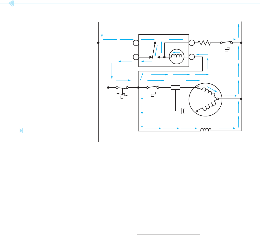
278 SECTION 5 Control Components
pigtail lead of the clock motor has been connected to
terminal 2 instead of terminal 1. Figure 28–7 shows
the current path during compressor operation. The
timer contact is making connection between ter-
minals 1 and 4. This permits power to be applied
to the thermostat. When the thermostat contact
closes, current is permitted to ow through the
compressor motor, the evaporator fan motor, and
the defrost timer motor. In this circuit, the timer
motor is connected in series with the defrost heater.
The operation of the timer motor is not affected,
however, because the impedance of the timer motor
is much greater than the resistance of the heater.
For this reason almost all the voltage of this circuit
is dropped across the timer motor. The impedance of
the timer motor also limits the current ow through
the defrost heater to such an extent that it does not
become warm.
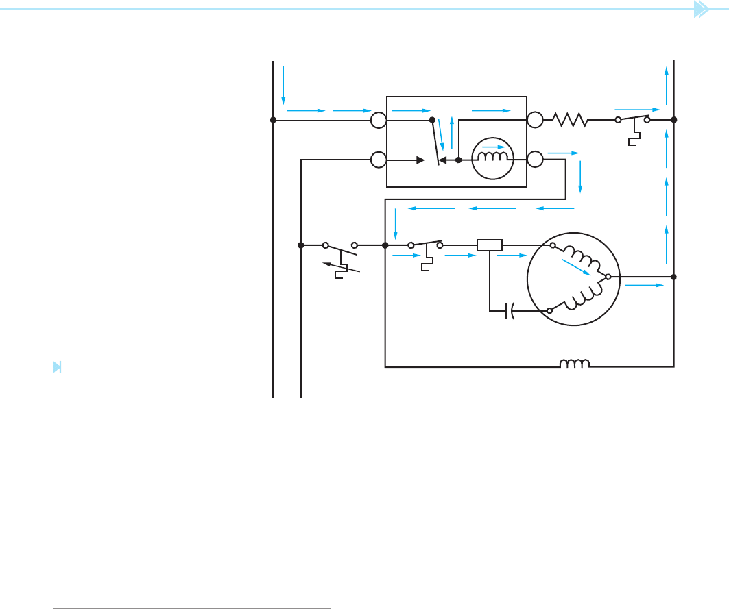
Figure 28–8 shows the current path through the
circuit when the defrost cycle has been activated.
Notice in this circuit that the defrost heater is con-
nected directly to the power line. This permits the
heater to operate at full power and melt any frost
accumulation on the evaporator. There is also a
current path through the timer motor and run wind-
ing of the compressor motor. In this circuit, the timer
motor is connected in series with the run winding
of the compressor. As before, the impedance of the
timer motor is much greater than the impedance
of the run winding of the compressor. This permits
almost all the voltage in this circuit to be applied
across the timer motor. At the end of the defrost
cycle, the timer contact returns to its normal posi-
tion and the compressor is permitted to operate.
TESTING THE TIMER
An ohmmeter can be used to check the continuity
of the contacts and the motor winding. However,
to really test the timer for operation takes time. The
cam can be manually turned to the position so that
the defrost cycle is turned on. This can be checked
with a voltmeter to determine when full circuit volt-
age is applied to terminal 2. It is then necessary to
H N
R
S
C
START
RELAY
COMPRESSOR
EVAPORATOR FAN
DEFROST
THERMOSTAT
OVERLOAD
THERMOSTAT
TIMER
DEFROST
HEATER
1
4
2
3
Figure 28–7
Current path during the cooling cycle.
(Source: Delmar/Cengage Learning)
UNIT 28 The Defrost Timer 279
H N
R
S
C
START
RELAY
COMPRESSOR
EVAPORATOR FAN
DEFROST
THERMOSTAT
OVERLOAD
THERMOSTAT
TIMER
DEFROST
HEATER
1
4
2
3
Figure 28–8
Current path during the defrost cycle.
(Source: Delmar/Cengage Learning)
wait long enough for the timer to open the contact
to the defrost heater and reconnect the compressor
circuit. If the thermostat is closed, the compressor
will start when the timer contact changes position.
This test shows that the timer motor is operating
and that the contact does change position.
COMMERCIAL DEFROST TIMERS
Many large commercial refrigeration units often
use a separate timer clock to control the defrost
cycle. This has several advantages over the previ-
ously discussed defrost timer. When this method is
used, the timer clock is connected directly across
the power line as shown in Figure 28–9. This sepa-
rates the operation of the timer from the operation
of the compressor. In this way, the defrost cycle
can be started during periods when the unit is in
minimum use.
Timers of this type, Figure 28–10, generally
have two timed settings. One determines the time
of day or night the timer turns on. The second set-
ting determines how long the timer is permitted
to remain on. The timer shown in this example
can be started on even numbered hours of the
day or night. The center knob sets how long the
contacts are energized before they return to their
normal position. Once turned on, the contacts
can be set to remain in their energized position
for a minimum of two minutes to a maximum of
120 minutes.
This timer has a separate timer release solenoid
incorporated into its design. When the timer release
solenoid is energized, it causes the contacts to return
to their normal reenergized position immediately.
This permits the action of some type of external limit
switch, such as a temperature or pressure switch, to
terminate the defrost cycle.