Stephen L. Herman, Bennie Sparkman. Electricity and Controls for HVAC-R (6th edition)
Подождите немного. Документ загружается.


260
When a split-phase motor is started, it is often nec-
essary to disconnect the start windings when the
motor reaches about 75% of full speed. In an open
case motor, this job is generally done by the cen-
trifugal switch. Some single-phase motors are her-
metically sealed, however, and a centrifugal switch
cannot be used. When this is the case, a
starting
relay must be used. A starting relay is located
away from the motor and is used to disconnect the
start windings when the motor has reached about
75% of its full speed. There are four basic types of
starting relays in general use:
1. The hot-wire relay.
2. The current relay.
3. The potential relay.
4. The solid-state relay.
OBJECTIVES
After studying this unit the student should
be able to:
List the common types of starting relays
Describe the operation of a hot-wire
relay
Connect a hot-wire relay in a circuit
Describe the operation of a current
relay
Connect a current relay in a circuit
Describe the operation of a potential
relay
Connect a potential relay in a circuit
Describe the operation of a solid-state
starting relay
Connect a solid-state starting relay in
a circuit
Describe the operation, construction,
and connection of a solid-state hard
starting kit
Starting
Relays
UNIT 26
UNIT 26 Starting Relays 261
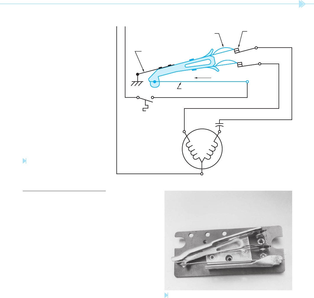
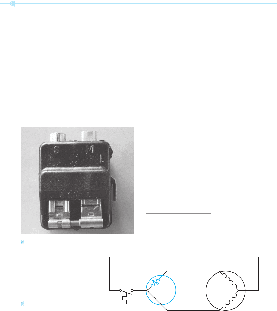
THE HOT-WIRE RELAY
The hot-wire relay is so named because it uses a
length of resistive wire connected in series with the
motor to sense motor current. A diagram of this type
of relay is shown in Figure 26–1. When the thermo-
stat contact closes, current can ow from line 1 to
terminal L of the relay. Current then ows through
the resistive wire, the movable arm, and the normally
closed contacts to the run and start windings. When
current ows through the resistive wire, its tempera-
ture increases. This increase of temperature causes
the wire to expand in length. When the length of the
resistive wire increases, the movable arm is forced
to move down. As the arm moves down, tension is
applied to the springs of both contacts. The relay
is so designed that the start contact will snap open
rst. When the start winding is disconnected, the
current ow to the motor will decrease. If the motor
current is not excessive, the resistive wire will not
expand enough to cause the run contact to open. If
the current ow is excessive, however, the wire will
continue to expand and the contact connected in
series with the run winding will open.
Notice that this type of relay is used as both a
starting relay and an overload relay. One disadvan-
tage of the hot-wire relay is that it must be permitted
to cool after each operation. A motor using this type
of starting relay cannot be started in rapid succes-
sion. Figure 26–2 shows a photograph of the hot-
wire type of starting relay.
MS
MOTOR
START CAPACITOR
L
2
L
1
R
U
N
S
T
A
R
T
C
M
S
OVERLOAD
CONTACT
L
SPRING METAL
RESISTIVE WIRE
START-WINDING
CONTACT
SPRING
Figure 26–1
Hot-wire relay connection.
(Source: Delmar/Cengage Learning)
Figure 26–2
Hot-wire type of starting relay. (Source: Delmar/Cengage Learning)
262 SECTION 5 Control Components
R
S
STARTING
CAPACITOR
START CONTACTS
CURRENT RELA
Y
COIL
THERMOSTAT
C
L
2
L
1
Testing this relay is dif cult. An ohmmeter can
be used to check for continuity between the L ter-
minal and the start and main winding terminals.
To properly test this relay, an ammeter should be
used to make certain the start contact opens and
disconnects the start winding. If the relay is open-
ing on overload, the ammeter can be used to check
the current draw of the motor. This will determine
if the motor is actually overloaded, or if the relay is
opening when it should not. A good rule to follow
concerning starting relays is to always test them if
the motor has been damaged. It makes poor busi-
ness sense to damage a new motor because of not
checking the starting relay.
When replacing this relay, it is necessary to use
the correct replacement. Because the relay is oper-
ated by motor current, it has been designed to open
its contacts when a speci c amount of current ows
through the circuit. The relay must, therefore, be
matched to the characteristics of the motor it is
intended to control.
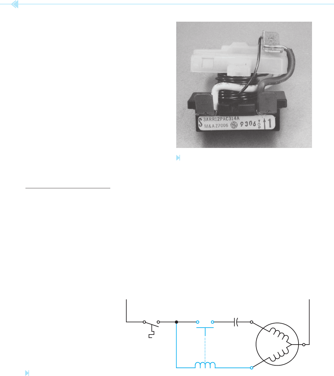
THE CURRENT RELAY
The current relay also operates by sensing the
amount of current ow in the circuit. This type of
relay operates on the principle of a magnetic eld
instead of expanding metal. The current relay con-
tains a coil of a few turns of large wire, and a set of
normally open contacts, Figure 26–3. The coil of the
relay is connected in series with the run winding of
the motor as shown in Figure 26–4. The contacts
are connected in series with the start winding.
When the thermostat contact closes and connects
Figure 26–4
Current relay connection. (Source: Delmar/Cengage Learning)
Figure 26–3
Current type of starting relay. (Source: Delmar/Cengage Learning)
power to the motor, the starting contacts of the
relay are open. Because no power is applied to the
start winding, the motor cannot start. This causes
a current of about three times the normal full-load
current to ow in the run winding. The high current
ow through the coil of the start relay produces a
strong magnetic eld. The magnetic eld is strong
enough to cause the solenoid to close the starting
contacts. When the starting contacts close, power
is applied to the start winding and the motor begins
to turn. As the motor accelerates, the current ow
through the run winding decreases rapidly. When
the current ow through the relay coil decreases,
UNIT 26 Starting Relays 263
the strength of the magnetic eld becomes weaker.
When the motor has reached about 75% of full
speed, the magnetic eld is weak enough to permit
the solenoid to reopen the starting contacts. This
disconnects the start winding from the circuit and
the motor continues to operate normally.
Notice that the current relay is used to disconnect
the start windings only and does not provide over-
load protection. A motor using this type of start-
ing relay must be provided with separate overload
protection.
If it is necessary to replace this type of relay, the cor-
rect size must be used. The current relay is matched
to the characteristics of the motor it is designed to be
used with. This type of relay is also sensitive to the
position it is mounted in. The current relay generally
uses the force of gravity to open the starting contacts.
When installing a new relay, it must be mounted in
the correct position. If it is installed upside down, the
starting contacts will be closed instead of open.
When testing this type of relay, an ohmmeter
can be used to check the continuity of the contacts.
When the relay is held in the correct position, the
ohmmeter should show an open circuit across the
contacts. If it does not, the contacts are shorted. If
the relay is held upside down, the contacts should
indicate continuity. The coil of the relay is generally
exposed and a visual inspection will reveal shorted
windings. The best method of testing the relay is
with an ammeter. If the ammeter is used to measure
the current ow to the start winding, it can be seen
if the motor starts and the relay contacts disconnect
the start winding.
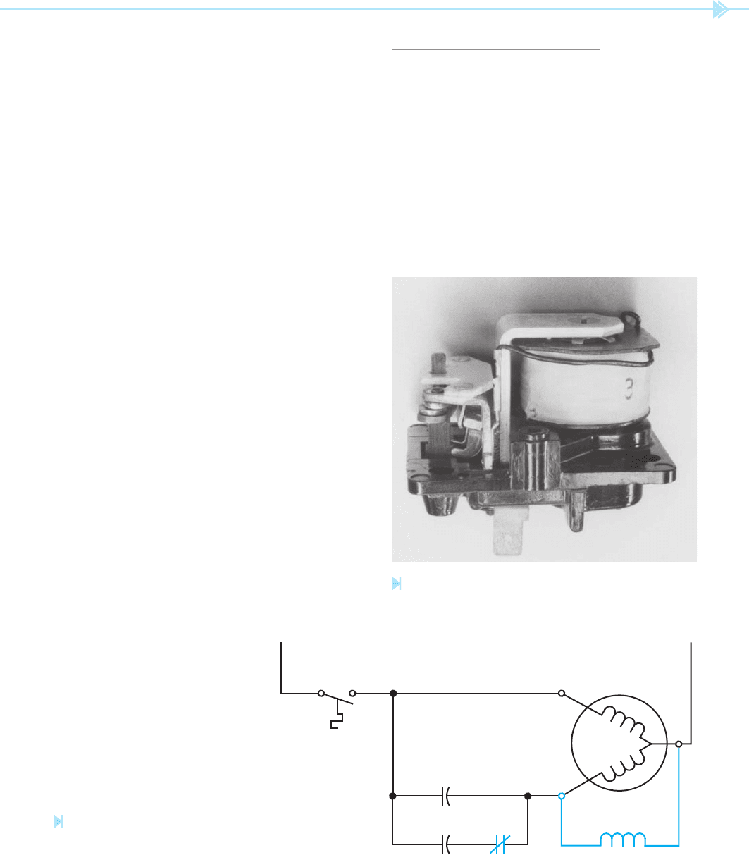
Figure 26–6
Potential relay connection.
(Source: Delmar/Cengage Learning)
Figure 26–5
Potential starting relay. (Source: Delmar/Cengage Learning)
S
SRSR
R
THERMOST
AT
C
L
2
L
1
START
CAPACITOR
RUN
CAPACITOR
THE POTENTIAL RELAY
The potential (voltage) relay operates by sens-
ing an increase in the voltage developed in the start
winding when the motor is operating. A potential
relay is shown in Figure 26–5. A schematic diagram
for a potential starting relay circuit is shown in
Figure 26–6. In this circuit, the potential relay is
used to disconnect the starting capacitor from the
circuit when the motor reaches about 75% of its
full speed. SR (starting relay) coil is connected in

264 SECTION 5 Control Components
parallel with the start winding of the motor. A nor-
mally closed SR contact is connected in series with
the starting capacitor. When the thermostat contact
closes, power is applied to both the run and start
windings of the motor. Notice that both the run
capacitor and the start capacitor are in the circuit
at this time.
The rotating magnetic eld of the stator cuts
through the bars of the squirrel-cage rotor and
induces a current into them. The current ow in the
rotor produces a magnetic eld around the rotor.
As the rotor begins to turn, its magnetic eld cuts
through the start winding and induces a voltage
into it. The induced voltage causes the total voltage
across the start winding to be higher than the volt-
age applied by the line. When the motor has acceler-
ated to about 75% of full speed, the induced voltage
in the start winding is high enough to energize SR
coil. When SR coil energizes, SR contact opens and
disconnects the start capacitor from the circuit,
Figure 26–7.
Notice that this type of relay depends on the
induced voltage created in the start winding by the
magnetic eld of the rotor and the run winding.
The start winding acts like the secondary winding
of a transformer and produces a step-up in voltage.
For this reason, the amount of voltage necessary to
energize the coil of a potential relay is greater than
line voltage. Once the relay has been energized it
can be held in by less voltage than that required to
energize it. The potential relay is primarily used to
disconnect the starting capacitor of a permanent-
split capacitor motor, as shown in Figure 26–6.
Although the potential relay is still in use, it is being
replaced by the solid-state relay.
The potential type of starting relay is often used
with compressors that use the permanent-split
capacitor start motor. The coil of the relay can be
tested for an open circuit with an ohmmeter. When
the ohmmeter is connected across the coil, it should
indicate continuity. The actual amount of resis-
tance can vary from one type of relay to another.
The best method for testing the starting relay is with
an ammeter. If an ammeter is connected to the start
capacitor, it can be seen if the capacitor is energized
when the motor is started, and if the relay discon-
nects it from the circuit.
SOLID-STATE STARTING RELAYS
Another type of starting relay is known as the
solid-state starting relay, Figure 26–8. This
relay is intended to replace the current-type start-
ing relay and has several advantages over the
current relay. Some of these advantages are:
1. The solid-state relay contains no moving
parts and no contacts, which can become
burned or pitted.
2. The solid-state relay can be used to replace al-
most any current relay. This interchangeabil-
ity makes it possible for the service technician
to stock only a few solid-state relays instead
of a large number of current relays.
The solid-state starting relay is actually an elec-
tronic component known as a thermistor. A
thermistor is a device that exhibits a change of
resistance with a change of temperature. This par-
ticular thermistor has a positive coef
cient of resis-
tance, which means that the resistance of the device
will increase with an increase of temperature.
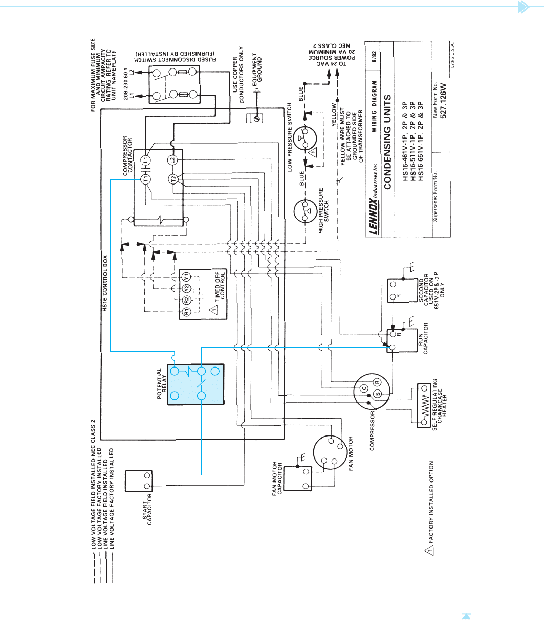
AUTHOR’S NOTE: A couple of things need
to be pointed out concerning the schematic in
Figure 26-7. One is that there is a mistake in the
terminal numbers of the potential relay. Termi-
nal numbers 1 and 2 should be switched. The
terminal shown as 2 is actually terminal 1, and
the terminal shown as 1 is actually terminal 2.
The second is not a mistake, but due to how the
schematic was drawn it could cause confusion.
Notice that the low-pressure switch has been
drawn upside down. The switch appears to be
a normally closed switch. In reality, it is a nor-
mally open held-closed switch. If the switch were
drawn properly, it would be apparent that the
switch is actually a normally open held-closed
switch. Although this schematic does contain a
mistake and a component not drawn properly,
I chose to retain it in the text. This is an excellent
example of problems that occur in the eld. The
service technician must be aware that mistakes
like this do happen.
UNIT 26 Starting Relays 265
-
.
.
4 5
2 1
6
-
Figure 26–7
A potential relay is used to disconnect the start windings of the compressor when the motor reaches about 75% of full speed. (Courtesy of Lennox Industries Inc.).
266 SECTION 5 Control Components
THERMOSTAT
N
S
C
R
MOTOR
START
RELAY
S
120 VAC
M
RUN
START
L
1
Figure 26–8
Solid-state starting relay. (Source: Delmar/Cengage Learning)
Figure 26–9
Solid-state starting relay connection.
(Source: Delmar/Cengage Learning)
resistance to change from a very low value of 3 or
4 ohms to several thousand ohms. This increase
of resistance is very sudden and has the effect of
opening a set of contacts connected in series with
the start winding. Although the start winding is
never completely disconnected from the power line,
the amount of current ow through it is very small,
typically 0.03 to 0.05 amps, and does not affect the
operation of the motor. This small amount of leak-
age current maintains the temperature of the
thermistor and prevents it from returning to a low
resistance. After power has been disconnected from
the motor, a cool-down period of about 2 minutes
should be allowed before restarting. This cool-down
period is needed for the thermistor to return to a low
value of resistance.
TESTING THE SOLID-STATE
STARTING RELAY
A continuity test can be made with an ohmmeter.
If the probes of an ohmmeter are connected to the
M and S terminals of the relay, a low value of resis-
tance, typically 2 to 5 ohms, should be seen. The
most accurate test is made by connecting the relay
in the motor circuit. A clamp-on ammeter set to its
lowest scale can be used to measure the current in
the start winding. After the motor has been started,
the ammeter should give an indication very close to
zero amps.
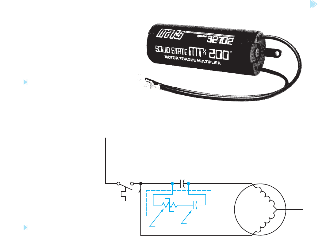
SOLID-STATE HARD
STARTING KIT
Another device that uses a solid-state relay, the
solid-state hard starting kit, is shown in
Figure 26–10. This device is intended to increase
The schematic diagram in Figure 26–9 illustrates
the connection for a solid-state starting relay. Notice
that this is the same basic connection used for the
connection of a current starting relay, Figure 26–4.
The solid-state relay, however, does not contain a coil
or contacts. When the solid-state relay is used, a cur-
rent path exists between the line connection terminal
and the terminal marked M for MAIN winding. The
thermistor is connected between the line connection
and the terminal marked S for START winding.
When power is rst applied to the circuit, the
thermistor has a relatively low resistance. This
permits current to ow through both the start and
run windings of the motor. The temperature of the
thermistor increases because of the current owing
through it. The increase of temperature causes the
UNIT 26 Starting Relays 267
Figure 26–10
Hard starting kit increases starting
torque of permanent-split capacitor
motors. (Courtesy of Motors & Armatures, Inc.)
Figure 26–11
Hard starting kit.
(Source: Delmar/Cengage Learning)
THERMOSTAT
N
S
C
R
MOTOR
120 VAC
RUN
START
L
1
RUN CAPACITOR
ELECTROLYTIC
CAP
ACITOR
SOLID
S TAT E
RELAY
the starting torque of a permanent-split capacitor
motor. The kit contains a solid-state relay and an
AC electrolytic capacitor similar to those used as
the starting capacitor for a capacitor-start induc-
tion run motor. The kit connects directly across the
terminals of the existing run capacitor as shown in
Figure 26–11. When the thermostat contact closes
and connects power to the motor circuit, the resis-
tance of the solid-state relay is very low. A current
path exists through the run winding, run capacitor,
solid-state relay, electrolytic capacitor, and start
winding. Because the run capacitor and electrolytic
capacitor are connected in parallel, their values of
capacitance add, providing extra capacitance to
the motor during the starting period. The current
owing through the solid-state relay and electro-
lytic capacitor causes the temperature of the relay
to increase, resulting in an increase in resistance.
The increased resistance reduces the current ow
through the electrolytic capacitor to a very low
value. This has the effect of disconnecting the
electrolytic capacitor from the circuit. The leakage
current through the relay and electrolytic capacitor
prevents the relay from returning to a low value of
resistance. After power has been disconnected from
the motor circuit, a cool down period of 2 to 3 min-
utes should be given to permit the solid-state relay
to return to a low value of resistance.

268 SECTION 5 Control Components
SUMMARY
Starting relays are used to disconnect the start winding of a hermetically sealed split-phase
motor.
The four basic types of starting relays are:
A. The hot-wire relay.
B. The current relay.
C. The potential relay.
D. The solid-state relay.
The hot-wire relay senses motor current by connecting a piece of resistive wire in series
with the motor. The motor current heats the wire, causing it to expand and open a set
of contacts.
Hot-wire relays can also provide overload protection for the motor.
Current relays use a coil connected in series with the motor run winding. The
magnetic eld of the coil is used to close a set of contacts connected in series with the
start winding.
The potential relay is used primarily with permanent-split capacitor motors.
The coil of the potential relay is connected in parallel with the motor start winding.
The contact of the potential relay is connected in series with the starting capacitor.
Solid-state starting relays are generally used to replace current starting relays.
Solid-state starting relays use a thermistor, which rapidly changes its resistance
when heated.
Solid-state hard starting kits generally consist of an AC electrolytic capacitor and a solid-
state starting relay that connect in parallel with the existing run capacitor.
KEY TERMS
current relay
hot-wire relay
leakage current
potential relay
solid-state hard starting kit
solid-state starting relay
starting relay
thermistor
REVIEW QUESTIONS
1. What are the four types of starting relays?
2. On what type of motor is it necessary to use a starting relay?
3. What principle is used to operate the hot-wire relay?
4. What principle is used to operate the current relay?
5. What type of starting relay does not sense motor current to operate?
6. What type of starting relay can be used for overload protection for the motor?
7. What type of motor can the potential relay be used with?

UNIT 26 Starting Relays 269
8. Is the start contact of a hot-wire relay open or closed when power is rst applied to the
motor?
9. Is the start contact of a current relay open or closed when power is rst applied to the
motor?
10. Refer to the circuit shown in Figure 26–4. What would happen if the coil of the cur-
rent relay were open when the thermostat connected power to the motor circuit?
TROUBLESHOOTING QUESTIONS
Refer to the schematic shown in Figure 26–7 to answer the following questions.
NOTE: T
he “TIMED OFF CONTROL” shown in the schematic is a short-cycle timer, which will be
discussed in Unit 36.
1. What voltage is used to operate the coil of the compressor contactor?
A. 208 VAC
B. 230 VAC
C. 60 VAC
D. 24 VAC
2. This schematic does not show the thermostat connection, which is relatively common
with air conditioning schematics. In which wire would the thermostat contact normally
be connected?
A. L1
B. L2
C. The blue wire
D. The yellow wire
3. Which of the following components is not controlled by the operation of the compressor
contactor?
A. Self-regulating crankcase heater
B. The fan motor
C. The compressor
D. All circuit components are controlled by the compressor contactor.
4. To which line is the common of the compressor connected?
A. The blue wire of the 24-volt circuit.
B. The yellow wire of the 24-volt circuit.
C. Line 1 of the main power.
D. Line 2 of the main power.
5. Assume that this unit is a model 651V-3P. How many capacitors are connected to the
compressor start winding during the initial starting period?
A. 1
B. 2
C. 3
D. None