Stephen L. Herman, Bennie Sparkman. Electricity and Controls for HVAC-R (6th edition)
Подождите немного. Документ загружается.


380 SECTION 6 Troubleshooting Using Control Schematics
the resistance heater through the high limit switch
and fuse, the thermostat controls the operation of
the heater. When the thermostat is connected in
this manner, a decrease in temperature will cause
the thermostat contacts to close and an increase in
temperature will cause them to open.
terminals COMPR B, and LO are connected to L1,
and terminal B is connected to terminal C. When
LO is connected to L1, the fan motor operates in the
low speed position. When terminal COMPR B is con-
nected to L1, power is provided to terminal 3 of the
thermostat. Terminal 2 is connected to terminal C of
the switch. Since switch terminal B is connected to
SUMMARY
Legends are sometimes used with schematic diagrams to aid in understanding.
A legend is a list of symbols and/or notations and gives the de nition of these symbols and/
or notations.
When using a schematic to interpret the operation of a circuit, it is generally helpful to
identify the major components in the circuit rst.
KEY TERMS
double-acting
electric resistance heating element
legend
major components
REVIEW QUESTIONS
1. What is a legend?
2. Refer to Figure 41–2. What would be the action of this circuit if the overload relay
should burn open?
3. What purpose does the thermistor connected in parallel with the capacitor serve?
4. In Figure 41–2, what switch connections are made when the switch is in the HI position?
5. In Figure 41–3, why is the thermostat switch as a single-pole double-throw?
6. In Figure 41–3, what do the dashed lines showing connection between the start
capacitor and start relay to other parts of the circuit mean?
7. In Figure 41–3, what color wire is connected between terminal 2 of the thermostat
and terminal C of the switch?
8. What color wire is connected between terminal 2 of the thermostat and the start relay?
9. In Figure 41–3, if no continuity is shown when one lead of an ohmmeter is connected
to switch terminal A and the other is connected to terminal C of the compressor, what
does it mean?
10. In Figure 41–3, to what two points should the terminals of an ohmmeter be con-
nected to check the continuity of the resistance heater circuit?

UNIT 41 Room Air Conditioners 381
TROUBLESHOOTING QUESTIONS
Refer to the schematic shown in Figure 41–3 to answer the following questions.
1. Assume that the switch has been set in the HI HEAT position. Now assume that the ther-
mostat controls the operation of the electric heating element, but does not control the
operation of the fan motor. Which of the following could cause this condition?
A. The thermostat is defective.
B. The high limit switch is stuck in the closed position.
C. The switch is not making connection between contacts B and C.
D. There is nothing wrong with the unit. This is normal operation for this unit.
2. When the switch is set in the LO COOL position, the unit will operate normally. When the
switch is set in the HI COOL position, the compressor will operate, but the fan motor will
not. Which off the following could cause this condition?
A. The fan motor winding between the red and black wire is open.
B. The fan motor winding between the black and brown wire is open.
C. The switch is not making connection between terminals COMPR A and HI.
D. The capacitor section between terminals C and F is defective.
3. When the switch is set in HI COOL or LO COOL position, the unit will operate normally.
When the switch is set in HI HEAT or LO HEAT position, the fan motor will operate nor-
mally, but the unit will not provide any heating. Which of the following could cause this
condition?
A. The thermostat is not making connection between 2 and 3.
B. The limit switch is open.
C. The fuse link is open.
D. All of the above.
4. When the switch is set in the LO COOL position, the unit will operate normally. When the
switch is set in the HI COOL position the fan motor will operate but the compressor will not
operate. Which of the following could cause this condition?
A. The overload unit is open.
B. The switch is not making contact between terminals A and C.
C. The potential starting relay is defective.
D. The thermostat is defective.

382 SECTION 6 Troubleshooting Using Control Schematics
5. Assume that the switch has been set in the LO COOL position, and the fan motor operates
normally. When the thermostat contact closes between terminals 1 and 2, the compressor
hums but does not start. An ohmmeter test of the compressor is as follows:
R to C 2 ohms
S to C 6 ohms
R to S 8 ohms
R to case in nity ohms
S to case in nity ohms
Which of the following would
not cause this problem?
A. Overload is open.
B. The capacitor between terminals C and HERM is defective.
C. The start capacitor is defective.
D. The potential starting relay is defective.

383
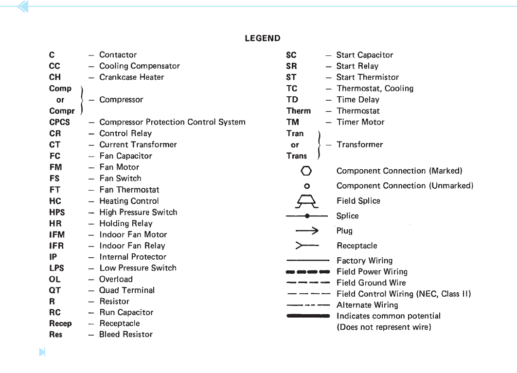
In this unit, a commercial air conditioning system
will be discussed. The legend for this schematic
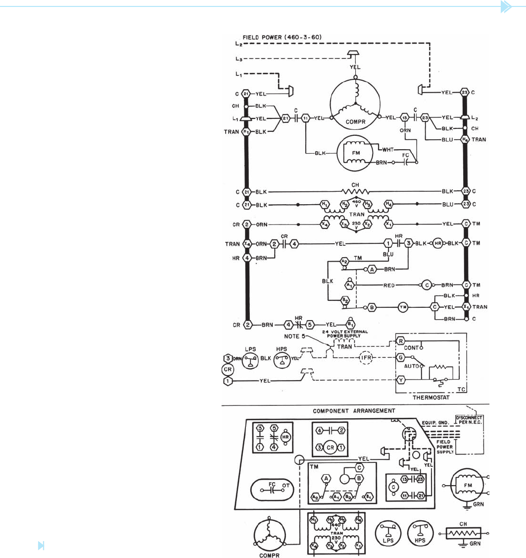
is shown in Figure 42–1. The schematic to be
discussed is shown in Figure 42–2. Notice that this
control system contains several devices not normally
found in a residential system. The compressor, for
example, is operated by a
three-phase squirrel-
cage induction motor. It can be seen that the
motor is three phase by the wye connection of the
stator winding. It can be determined that the motor
is a squirrel cage because it has no external resistors
that would be used for the rotor circuit of a wound
rotor induction motor. There is also no DC circuit
that would be required to excite the rotor of a three-
phase synchronous motor.
The condenser fan motor is a single-phase per-
manent split-capacitor motor. Notice that the con-
denser fan motor is connected in parallel with two
OBJECTIVES
After studying this unit the student should
be able to:
Recognize electrical components from
the symbols on the schematic
Discuss the operation of a commercial
air conditioning unit
Interpret a three-phase schematic
diagram
A Commercial
Air Conditioning
Unit
UNIT 42
384 SECTION 6 Troubleshooting Using Control Schematics
lines of the compressor. When contactor C ener-
gizes, both C contacts close and connect both the
compressor and condenser fan motors to the line.
The
crankcase heater is shown directly
below the condenser fan motor, and is connected to
terminals 21 and 23. Notice the crankcase heater
is energized at all times. As long as power is con-
nected to the circuit, the crankcase heater will be
energized.
The control transformer contains two pri-
mary windings and two secondary windings. This
transformer can be connected to permit a 460- or
230-volt connection to the primary, and the sec-
ondary can provide 230 or 115 volts. In the circuit
shown, the primary winding is connected in series,
which permits 460 volts to be connected to it. The
secondary winding is also connected in series, which
provides an output voltage of 230 volts.
The 230-volt circuit is used to operate a short-
cycle timer circuit. This is the same circuit that was
discussed in Unit 35.
The 24-volt circuit is shown at the bottom of
the schematic. Notice that only the secondary of
the transformer is shown. This is indicating that its
power can be derived from almost anywhere. The
primary of this transformer could be connected to
a 120-volt circuit inside the building. This circuit
contains the high- and low-pressure switches. If one
of them should open, it will have the same effect as
opening the thermostat.
Notice that the
indoor fan relay (IFR) is
shown, but the fan motor is not. In a commercial
location, there may actually be several fans oper-
ated by the IFR relay. In practice, the IFR relay may
be used to control the coils of other relays, which
connect the fan motors to the line.
Figure 42–1
Schematic legend. (Courtesy of Carrier Corp.).
UNIT 42 A Commercial Air Conditioning Unit 385
Figure 42–2
Schematic diagram. (Courtesy of Carrier Corp.).

386 SECTION 6 Troubleshooting Using Control Schematics
The thermostat is a single-pole single-throw con-
tact. The resistor shown connected around the
thermostat contact represents the heat anticipator.
A switch is also provided that will permit the indoor
fan to be operated automatically or manually.
The last item shows the component arrangement.
This is used to aid the service technician in locating
the different control components in the system.
SUMMARY
The compressor in this example circuit is powered by a three-phase squirrel-cage motor.
The windings in the compressor motor are connected in a wye con guration.
The condenser fan motor is a single-phase permanent-split capacitor motor.
The control transformer contains two primary and two secondary windings.
The thermostat, low-pressure switch, and high-pressure switch are connected to a 24-volt
system.
The control system for this unit contains a short-cycle timer.
KEY TERMS
crankcase heater
indoor fan relay (IFR)
three-phase squirrel-cage induction motor
REVIEW QUESTIONS
1. What does the term CC mean if seen on a control schematic?
2. What does the term CPCS mean if seen on a schematic?
Refer to Figure 42–2 for the following questions.
3. If it is desired to change the voltage controlling the short-cycle timer from 230 volts
to 115 volts, what transformer leads should be connected together?
4. Assume the system has stopped operation. A voltmeter is connected across the LPS
switch terminals and it indicates 24 volts. The voltmeter is then connected across
the HPS switch and it indicates 0 volts. Which switch is stopping the operation of the
circuit?
5. When the system is operating normally, how much voltage should be seen across the
CR relay coil?

UNIT 42 A Commercial Air Conditioning Unit 387
TROUBLESHOOTING QUESTIONS
Refer to the schematic shown in Figure 42–2 to answer the following questions.
1. Referring to the schematic in its present state, will the compressor start with the
thermostat in the closed position? Explain your answer.
A. Yes
B. No
2. What voltage is used to operate the short-cycle timer and compressor relay?
A. 460 VAC
B. 230 VAC
C. 120 VAC
D. 24 VAC
3. What relay controls the operation of the condenser fan motor?
A. IFR
B. HR
C. C
D. CR
4. Which of the following components is not shown on the schematic?
A. COMPRESSOR MOTOR
B. CONDENSER FAN MOTOR
C. THERMOSTAT
D. EVAPORATOR FAN MOTOR
5. Assume that the unit is in operation and suddenly stops. A voltmeter test reveals the
following information:
Voltage across L
1
, L
2
, and L
3
⫽ 460 VAC
Voltage across X
1
to X
4
of the control transformer ⫽ 230 VAC
Voltage across CR coil ⫽ 24 VAC
Voltage across terminals 2 and 4 of the CR contact ⫽ 230 VAC
Voltage across coil C ⫽ 0
What is the most probable cause of trouble? Explain your answer.
A. CR coil is open.
B. CR contacts are stuck closed.
C. Coil HR of the short-cycle timer is open.
D. Coil C is open.

A heat pump is a device that provides both heating
and air conditioning within the same unit. In the
cooling cycle, the outside heat exchange unit is used
as the condenser and the inside heat exchanger
is used as the evaporator. When the heat pump is
used for heating, the reversing valve reverses the
ow of refrigerant in the system and the outside heat
exchanger becomes the evaporator. The inside heat
exchanger becomes the condenser. Heat pumps also
contain some type of back-up heating system that
is used when the outside temperature is too low to
make heat transfer ef cient. The most common type
of back-up heat is electric-resistance heat.
Heat pumps contain other control devices that
are generally used only with heat-pump equipment,
such as two-stage thermostats, sequence relays, and
defrost timers.
388
OBJECTIVES
After studying this unit the student should
be able to:
Describe the operation of a heat pump
Discuss the function of a double-acting
thermostat in a heat-pump system
Discuss the operation of a sequence
timer
Describe the operation of the defrost
thermostat and timer
UNIT 43
Heat-Pump
Controls
UNIT 43 Heat-Pump Controls 389
DEFROST TIMER
When the heat pump is used in the heating mode of
operation, it removes heat from the air and delivers
it inside the living area. This means that the outside
heat exchanger is being used as the evaporator and
cold refrigerant is circulated through it. Any mois-
ture in the air can cause frost to form on the coil
and reduce the air ow through it. This will reduce
the ef ciency of the unit. For this reason, it is gener-
ally necessary to defrost the outside heat exchanger.
Defrosting is done by disconnecting the condenser
or outside fan motor and reversing the ow of
refrigerant through the coil. This causes the unit to
temporarily become an air conditioner and warm
refrigerant is circulated through the coil.
Before the defrost cycle can be activated,
two separate control conditions must exist. The
defrost thermostat, located on the outside heat
exchanger, must be closed; and the defrost timer
must permit the defrost cycle to begin. A schematic
diagram of a basic defrost control circuit is shown
in Figure 43–2. Notice that the defrost timer is con-
nected in parallel with the compressor. This means
that the timer can operate only when the compres-
sor is in operation. Notice also that the defrost cycle
energizes the
reversing valve solenoid. This
means that this unit is in the heating mode when
the solenoid is deenergized.
Notice the defrost timer contains two contacts,
DT1 and DT2. DT1 is normally open and DT2 is
normally closed. The defrost relay (DFR) contains
three contacts. DFR1 is normally closed and is con-
nected in series with the outside fan motor. DFR2
is normally open and is connected in parallel with
contact DT1. Contact DFR3 is normally open and is
connected to the reversing valve solenoid.
The schematic shown in Figure 43–3 illustrates
the condition of the circuit when the defrost cycle
rst begins. Notice that the defrost timer (DT) has
caused contact DT1 to close, but contact DT2 has
not opened. The contacts of the defrost timer are
operated by two separate cams. The cams are so
arranged that contact DT1 will close before DT2
opens.
The schematic in Figure 43–4 illustrates the
condition of the circuit immediately after the defrost
relay has energized. Notice that all DFR contacts
TWO-STAGE THERMOSTATS
The two-stage thermostat is a thermostat that con-
tains two separate mercury contacts. It is similar to
the programmable thermostat except that the two
mercury contacts cannot be set independently of
each other. The mercury contacts of the two-stage
thermostat are so arranged that one contact will
make connection slightly ahead of the other. For
example, assume the heat pump is being used in the
heating mode. Now assume that the temperature
drops. One of the contacts will make connection
rst. This contact turns on the compressor and heat
is provided to the living area. If the compressor can
provide enough heat to raise the temperature to the
desired level, the second mercury contact does not
make connection. If the compressor cannot provide
the heat needed, the second mercury contact will
close and turn on the electric-resistance heating ele-
ments to provide extra heat to the living area.
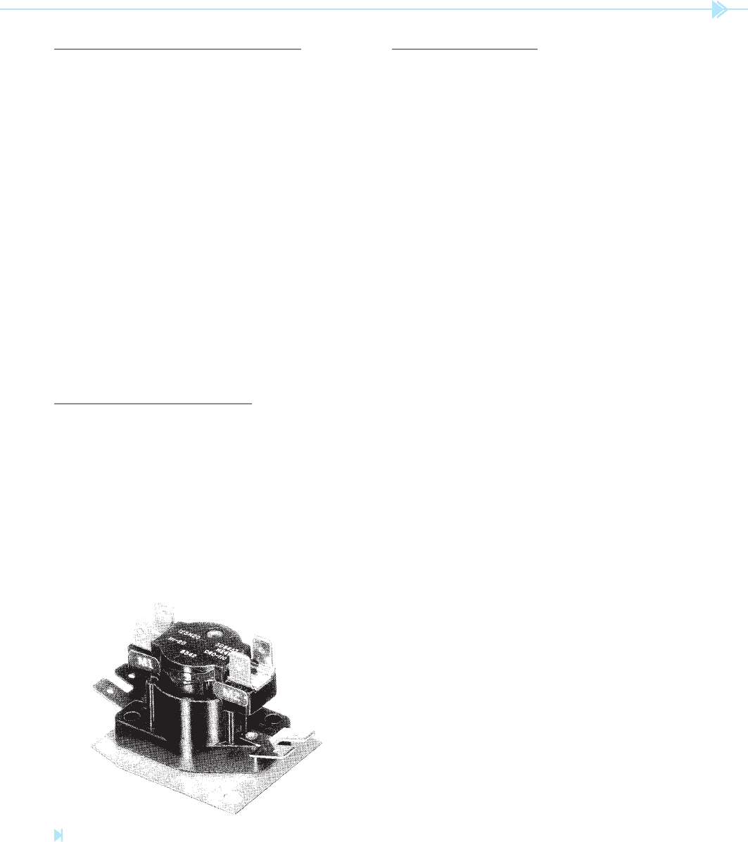
THE SEQUENCE TIMER
The sequence timer is an on-delay timer used
to connect the heating elements to the line in stages
instead of all at once. Most sequence timers contain
two or three contacts and are operated by a small
heating element that heats a bimetal strip. When the
bimetal strip becomes hot enough, it snaps from one
position to another and closes the two contacts. A pho-
tograph of this type of timer is shown in Figure 43–1.
Figure 43–1
Sequence relay. (Courtesy of Emerson Electric Co., White-Rodgers Division).