Stephen L. Herman, Bennie Sparkman. Electricity and Controls for HVAC-R (6th edition)
Подождите немного. Документ загружается.

370 SECTION 6 Troubleshooting Using Control Schematics
Because each element has a power rating of
5,000 watts, the ampere draw of each element can
be determined using Ohm’s law.
I ⫽
P
__
E
I ⫽
5000
_____
240
I ⫽ 20.8 amperes
is actually operating or not. Assume that you are
troubleshooting an electric furnace. Also assume
that the furnace has three stages rated at 5 kW
each. The stages are generally sequenced so they
come on one at a time. A very fast method of check-
ing the furnace is to connect a clamp-on ammeter to
the incoming line, turn on the heat, and watch the
readings on the ammeter, Figure 40–17.
L2L1
FR FR
THERMOSTAT
FUSE
HP LP FL
TRANSFORMER 240/24
CC
FR
FAN MOTOR
COMPRESSOR
240 VAC
CC CC
OL
C
R
S
Ω
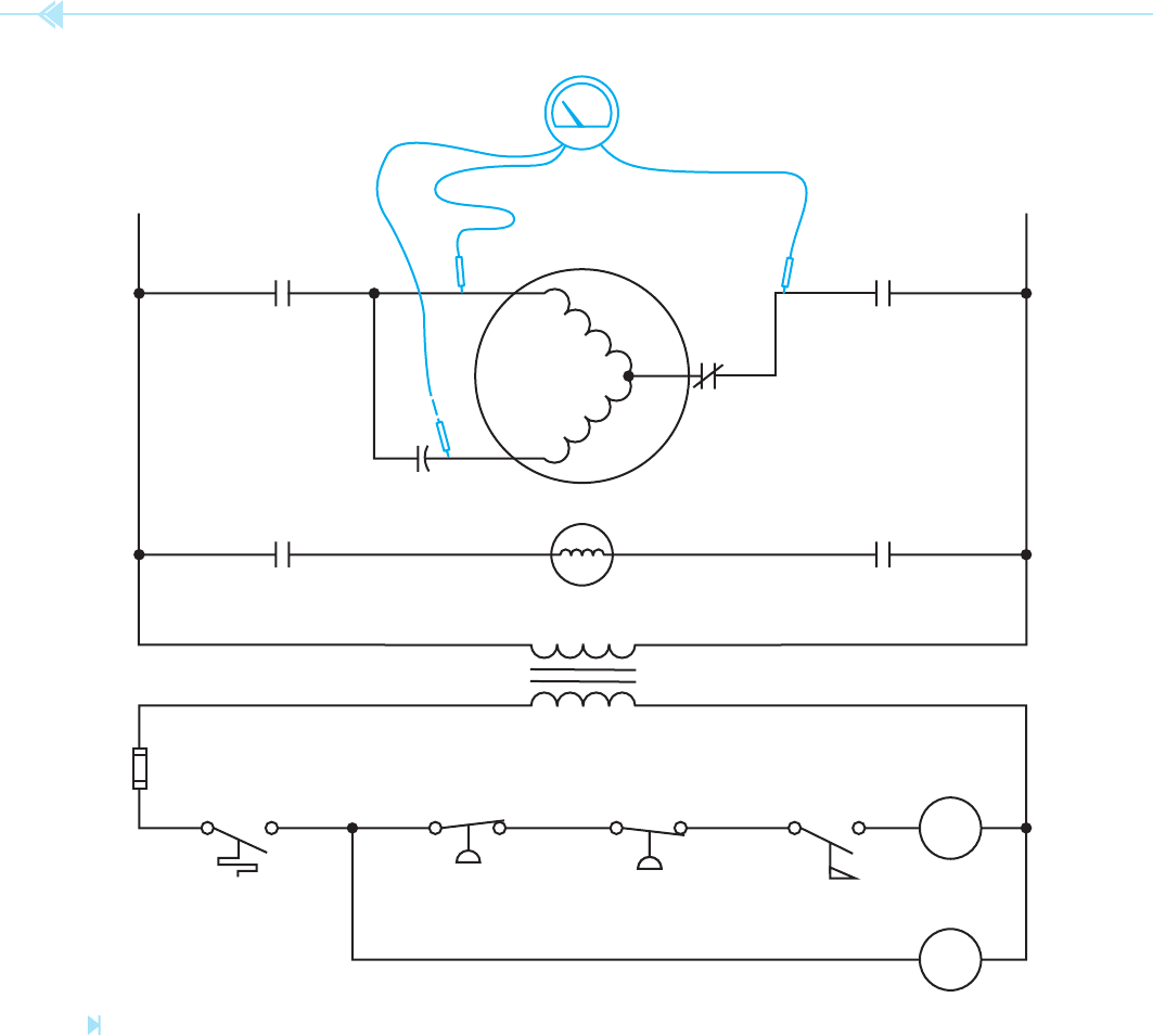
Figure 40–14
An ohmmeter is used to test the windings for continuity. (Source: Delmar/Cengage Learning)
UNIT 40 Introduction to Troubleshooting 371
determine if voltage is being applied to each ele-
ment, but unless the power was turned and off and
the heating elements disconnected and tested with
an ohmmeter, you could not be certain an ele-
ment was not burned open. The ammeter permits
a quick check of the unit and you know that each
element is operating.
When the furnace is energized, the ammeter
should indicate a current ow of approximately
21 amperes. After a few minutes the current should
increase to approximately 42 amperes (20.8 ⫹
20.8 ⫽ 41.6), and after another delay the current
should increase to approximately 62.5 amperes
(20.8 ⫻ 3 ⫽ 62.4). A voltmeter could be used to
L2L1
FR FR
THERMOSTAT
FUSE
HP LP FL
TRANSFORMER 240/24
CC
FR
FAN MOTOR
COMPRESSOR
240 VAC
CC CC
OL
C
R
S
Ω
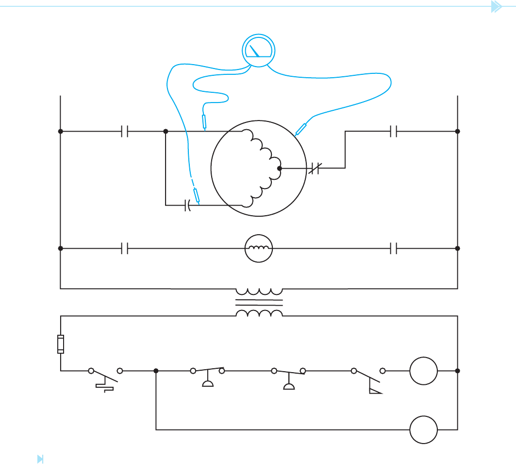
Figure 40–15
Each winding is tested for a grounded condition. (Source: Delmar/Cengage Learning)
372 SECTION 6 Troubleshooting Using Control Schematics
1. Check the power supply. To do this, set
the fan switch to ON or MAN to see if the
blower fan turns on. If it does, you have
determined that the 24-volt supply is
working. If the blower does not turn on, the
problem could be the thermostat, fan relay,
blower motor, run capacitor, 24-volt trans-
former, or main power supply to the trans-
former. At this point you have determined
if the problem is with the inside unit or the
outside unit.
THE SHOTGUN METHOD
As stated previously, most technicians will adopt
their own troubleshooting methods that are devel-
oped with time and experience. The
shotgun method
involves testing the circuit at various locations to
determine trouble areas rather than following a
step-by-step procedure as outlined in the hopscotch
method. In this example, the circuit to be tested is a
central air conditioner and electric heating system.
Probably the best place to start is at the thermostat
because it is readily accessible.
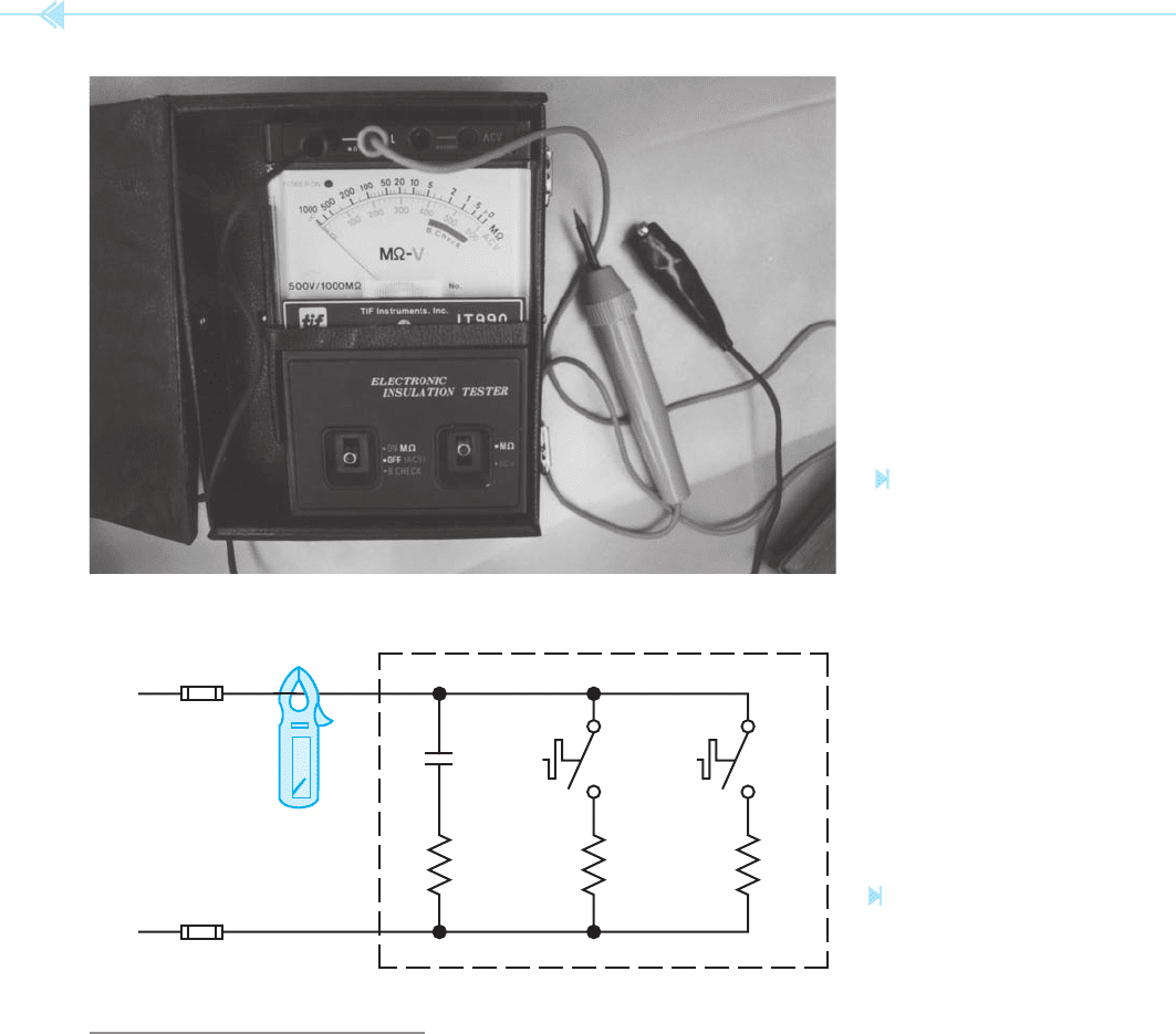
Figure 40–16
A megohmmeter for
testing insulation
resistance. (Source: Delmar/
Cengage Learning)
SEQ.
5kW
SEQ.
5kW
ELECTRIC FURNACE
HR
240 VOLTS
5kW
Figure 40–17
Testing an electric
furnace with an ammeter.
(Source: Delmar/Cengage Learning)

UNIT 40 Introduction to Troubleshooting 373
8. If all components between the contactor and
compressor are good, check the power sup-
plied to the compressor terminals. If power is
present at the compressor terminals, discon-
nect power to the outside unit by opening the
disconnect switch or circuit breaker.
9. Disconnect the power terminals connected to
the compressor. Use an ohmmeter and check
between each terminal to determine if there is
an open circuit. Also check between each ter-
minal and the compressor case to determine if
there is a grounded circuit. Note: It is possible
for the motor windings to be shorted and not
be open or grounded. Shorted windings will
cause the motor to draw an excessive amount
of current or may not permit the compressor
to start when power is supplied. An ohmmeter
generally will not reveal this condition.
10. If the ohmmeter indicates an open circuit
in the compressor, note if the compressor is
hot to the touch. If so, the internal overload
may be open. It cannot be determined if the
compressor winding is open or if the internal
overload is open until the compressor cools.
This overload cannot be bypassed. If the com-
pressor is hot, it may take hours for the over-
load to reset, depending on the temperature
of the compressor, the ambient temperature,
and whether the compressor is located in
direct sunlight. The only way to know if the
compressor is defective or if another problem
caused the overload to open is to wait until
the overload resets. It is recommended to
leave the power disconnected to the outside
unit until the compressor cools and allows
the overload to reset. This will allow the tech-
nician to observe whether the compressor
restarts or not.
11. Some of the circumstances that can cause the
internal overload to open are:
• Defective windings in the compressor,
causing it to draw excessive current.
• A stuck compressor.
• A brief power interruption, such as a loss
of power or someone opening the thermo-
stat contacts and reclosing them.
2. Test the thermostat. Remove the thermostat
from its base and check the wires connected
to the thermostat base with a voltmeter to
determine if 24 volts is available. If 24 volts
is available, use a fused jumper to test the
circuit components controlled by the thermo-
stat. Connect one lead to the power terminal
(R) and make connection to each of the other
terminals to determine if there is a response.
If there is a response to each of the terminals,
the thermostat is defective.
3. If there was not a response to a particular cir-
cuit component, replace the thermostat on the
base and check that component starting with
the power supply. In this example, assume
that the air conditioning unit did not respond.
4. Check the 240-volt power supply to the unit.
This can be checked at the breaker, discon-
nect switch, or main contactor depending on
which is most accessible. In this example it
will be assumed that power is present at the
main contactor.
a. Check the output of the main contactor
to determine if power is being supplied to
the compressor. If not, check the 24-volt
supply to the coil of the main contactor.
If 24 volts is supplied to the coil, the
contactor is defective.
5. If 24 volts is not present at the coil of the
contactor, check the thermostat wires where
they enter the outside unit. If power is not
present, check the wiring between the ther-
mostat and the outside unit.
6. If 24 volts is present at the unit, check any
components between the 24-volt supply and
the coil of the contactor. Components such
as high-pressure switches, low-pressure
switches, and so on are connected in series
with the low-voltage circuit.
Now assume that instead of no response at the
outside unit, the condenser fan started but the
compressor did not.
7. If 240 volts is available at the output of the
main contactor, check all components, such
as run and start capacitors, between the con-
tactor and the compressor.
374 SECTION 6 Troubleshooting Using Control Schematics
vapor returning from the evaporator to
help cool the motor.
• Very high ambient temperature and being
exposed to direct sunlight.
12. If the compressor eventually restarts,
check the current draw of the unit and
compare this reading to the nameplate cur-
rent rating. If the current draw is greater
than the full-load-amp (FLA) draw listed on
the nameplate, determine if the problem is
a defective compressor or one of the other
causes listed.
• Lack of air ow across the condenser and
compressor. This can be caused by a dirty
condenser or anything blocking air to the
condenser. The condenser fan can also be
defective and thus prevented from obtain-
ing full speed.
• Low voltage supplying the compressor.
• Over charge of refrigerant causing high
head pressure. This would cause the com-
pressor to draw excessive current.
• Low charge of refrigerant. The compressor
could overheat because it depends on cool
SUMMARY
Before it is possible to troubleshoot a circuit, the technician must have an understanding
of how the circuit operates.
The three main instruments used for troubleshooting are the voltmeter, ohmmeter, and
ammeter.
Power must always be disconnected from the circuit before using an ohmmeter.
A complete circuit must exist before a voltmeter will indicate voltage.
An ammeter is used to determine if current is actually owing through the circuit.
The hopscotch method of troubleshooting involves starting at one of the circuits and mov-
ing from component to component until the problem is discovered.
KEY TERMS
ammeter hopscotch method ohmmeter
electrical pressure measuring instruments voltmeter
fused jumper
REVIEW QUESTIONS
1. A voltmeter is connected across the terminals of an electric heating element. The
voltmeter indicates a voltage of 240 volts. Is this a true test to determine if the heating
element is operating?
2. What electrical measuring instrument should be used to determine if the heating ele-
ment in question 1 is operating?

UNIT 40 Introduction to Troubleshooting 375
3. It is suspected that the high-pressure switch in a control circuit is open. Explain the
steps in testing this component with an ohmmeter.
4. Refer to Figure 40–10. Assume that the voltmeter indicates a value of 24 volts, but
the compressor contactor is not energized. What is the most likely problem?
A. A jumper wire was not placed around the thermostat contacts.
B. The ow switch is open.
C. The coil of the CC contactor is open.
D. The coil of the CC contactor is shorted.
5. Refer to the circuit in Figure 40–7. Assume that when a jumper is placed around the
thermostat contacts, the fan motor starts, the compressor contactor energizes, but the
compressor motor does not start. Which of the following could not cause this problem?
A. The ow switch is not closing.
B. The CC load contacts are defective.
C. The compressor overload relay is open.
D. The compressor start capacitor is defective.

In the previous units, basic symbols and rules for
reading a schematic diagram have been covered.
In actual practice, however, schematics do not
always look like the classic textbook examples.
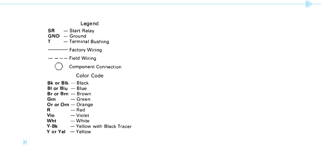
Many schematic diagrams use a
legend to aid
in understanding. A legend is a list that shows a
symbol or notation and gives the de nition of that
symbol or notation. The legend that will be used
with the schematics presented in this unit is shown
in Figure 41–1.
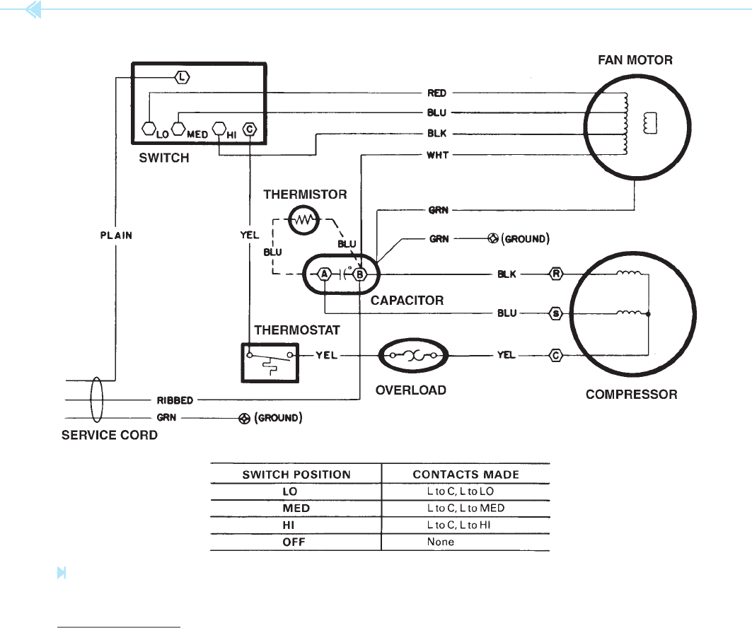
SCHEMATIC 1
The rst circuit to be discussed is shown in
Figure 41–2. First nd the major components
shown on the schematic: the switch, fan motor, com-
pressor, capacitor, overload, and thermostat. Notice
that these components may not be shown exactly as
376
OBJECTIVES
After studying this unit the student should
be able to:
Identify circuit components on a
schematic diagram
Analyze a schematic diagram to
determine how the circuit functions
UNIT 41
Room Air
Conditioners
UNIT 41 Room Air Conditioners 377
represent the run winding. The middle terminal is
labeled with an S, which represents the start wind-
ing terminal, and the third terminal is labeled with
a C, which indicates the common terminal. Trace
the common terminal through the overload and
thermostat to terminal C on the switch. Notice
that the thermostat and overload are connected
in series with the compressor. Now trace the run
lead of the compressor. Notice that it is connected
to the B terminal of the capacitor. This shows that
the run winding is connected to the common side
of the service chord. Now trace the start lead to the
A side of the capacitor. Notice that the capacitor is
connected in series between the common side of the
service chord and the start winding. The thermistor
connected across the capacitor terminals is used to
decrease the capacitance connected in series with
the compressor after the compressor is in operation.
Recall that a thermistor is a temperature-sensitive
resistor. This thermistor has a negative temperature
coef cient, which means that it will have a very
high resistance when it is cool. When its tempera-
ture increases, its resistance will decrease. When
the compressor is rst started, the thermistor is cool
because no current has been owing through it.
This causes its resistance to be much greater than
the capacitive reactance of the capacitor. The full
amount of the capacitor is now connected in series
with the start winding.
As current ows through the thermistor, its tem-
perature begins to increase. This causes a decrease
in its resistance, which permits more current to
ow. As the resistance of the thermistor decreases,
the effect of the capacitor on the motor decreases
also. The effect is very similar to having a compres-
sor that has both a start and run capacitor in the
circuit for starting, and then disconnecting the start
capacitor and permitting the motor to operate with
the run capacitor only.
The last component to be discussed is the switch.
Notice that it is not shown with internal electrical
connections. There is a legend at the bottom of the
schematic, however, that shows which terminals
are connected when the switch is set in different
positions. In the LO position, for example, terminal
L is connected to both the LO fan speed position and
the C position, which permits the thermostat to con-
trol the compressor.
Figure 41–1
Schematic legend. (Courtesy of Carrier Corp.).
you would expect. Notice the overload symbol, for
example. The symbol used is the same as the symbol
for an overload heater discussed earlier in the text.
There are, however, no overload contacts shown.
The schematic is indicating the use of a small, single-
phase bimetal overload unit that acts as both heater
and overload contact.
Next, nd and examine the fan motor. Notice that
this motor has several windings that indicate that it
is used for multispeed operation. Notice also that
there is no capacitor connected to this motor. The
small winding shown separate is the start winding.
Because there is no start or run capacitor shown,
this motor is a resistance start induction run. Notice
that the white wire is connected from the motor to
B terminal of the capacitor and then to one lead of
the service chord. This indicates that the white wire
is common to the other windings. Now trace the
connection of the red, blue, and black wires. The
red wire is connected to the LO speed position on
the switch; the blue wire is connected to the MED
speed position and the black wire is connected to the
HI speed position.
Next, examine the compressor. Notice that two
windings are shown. Each winding is connected
to a terminal. One terminal is labeled with an R to
378 SECTION 6 Troubleshooting Using Control Schematics
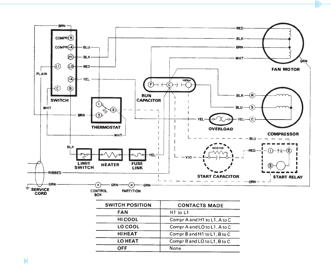
two capacitors contained in the same case. The junc-
tion point between the two capacitors is connected
to one side of the service chord. The fan motor in this
unit is different also. Notice that this fan used a run
capacitor connected in series with the start winding
of the motor at all timers. This motor is a permanent
split-capacitor motor. Notice that this motor has
two speeds instead of three.
The start capacitor is connected in parallel with
the run capacitor to increase the starting torque
of the compressor. The resistor shown connected
across the terminals of the start capacitor is a
relatively high value of xed resistance used to dis-
charge the capacitor when it is disconnected from
SCHEMATIC 2
The second schematic to be discussed is shown in
Figure 41–3. This schematic is for another room-
type air conditioner, but it has some added com-
ponents. This unit is used to provide heat as well
as cooling. An
electric resistance heating
element
is used to provide heat in cool weather.
Notice also the addition of the start capacitor
and start relay. The thermostat in this circuit is
double-acting instead of a single-pole single-
throw. This permits the same thermostat to be used
for both heating and cooling. Notice also that the
run capacitor is different. This capacitor is actually
Figure 41–2
Schematic diagram. (Courtesy of Carrier Corp.).
UNIT 41 Room Air Conditioners 379
connected to L1, the fan motor will operate in its
high speed. When terminal COMPR A is connected
to L1, a current path is provided to terminal 1 of the
thermostat. Terminal 2 is connected to terminal C
of the switch. Since switch terminal A is connected
to switch terminal C, power is connected to the
compressor motor through the thermostat contact.
When the thermostat is connected in this manner,
an increase in temperature will cause the thermo-
stat contacts to close and a decrease in temperature
will cause them to open.
Now assume that the switch has been set to the
low heat position. The switch legend indicates that
the circuit. Notice the start relay. The start capacitor
is connected in series with the normally closed con-
tact. This is a potential starting relay, which senses
the voltage induced in the start winding and opens
the contact when the motor reaches about 75% of
its full speed.
In this circuit, the switch is the main control-
ler. For example, trace the circuit when the switch
is placed in the high cool position. The legend at
the bottom of the schematic indicates that when
the switch is in the HI cool position, terminals
COMPR A and HI are connected to terminal L1, and
terminal A is connected to terminal C. When HI is
Figure 41–3
Room air conditioner circuit. (Courtesy of Carrier Corp.).