Stephen L. Herman, Bennie Sparkman. Electricity and Controls for HVAC-R (6th edition)
Подождите немного. Документ загружается.

350 SECTION 5 Control Components
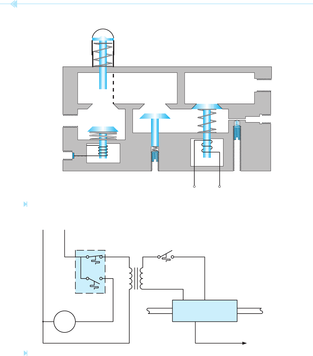
To
Thermostat
Pilot
Adj.
Pressure
Adj.
To Pilot
Light
Outlet
Cock
Window
Pilot Valve
Inlet
To
T
hermocouple
Regulator
Main
Valve
Off-Pilot-On
Figure 38–4
Basic gas control valve. (Source: Delmar/Cengage Learning)
NL
FAN-LIMIT
SWITCH
THERMOSTAT
GAS CONTROL
VALVE
BLOWER
MOTOR
24 VOLTS
GAS INLET
GAS OUTLET
TO THERMOCOUPLE
Figure 38–5
Basic gas control system. (Source: Delmar/Cengage Learning)
UNIT 38 Gas Burner Controls 351
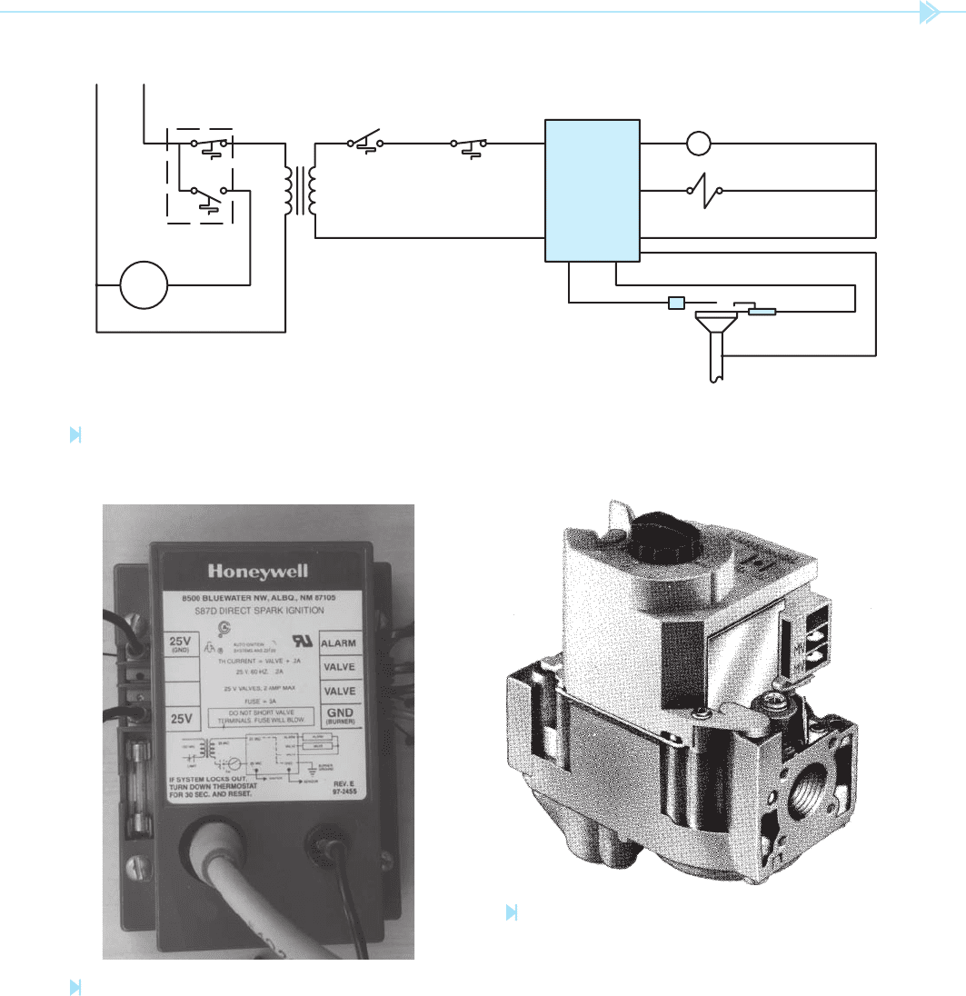
NL
FAN LIMIT
SWITCH
THERMOSTAT
BLOWER
MOTOR
24 VOLTS
AUX. HIGH
LIMIT IF
USED
DIRECT
SPARK
IGNITION
CONTROL
ALARM RELAY
IF USED
GAS CONTROL
VALV E
FLAME
ROD
ELECTRIC
IGNITOR
MAIN BURNER
Figure 38–6
Electric spark-ignition control. (Source: Delmar/Cengage Learning)
Figure 38–7
Direct spark-ignition control module. (Courtesy of Honeywell Inc.).
If a ame is not established when the thermostat
calls for heat, the timer will shut down the system in
the same manner. A direct ignition control module
is shown in Figure 38–7, and a gas control valve
used with an electric spark-ignition system is shown
in Figure 38–8.
Figure 38–8
Main gas valve used with electric ignition. (Courtesy of
Honeywell Inc.).

352 SECTION 5 Control Components
SUMMARY
The primary function of a gas burner control is to ensure that gas is not permitted to enter
the system if it cannot be ignited in a safe manner.
The oldest method of automatically igniting a gas burner is with a pilot light.
A thermocouple is used to sense the presence of a pilot light before gas is permitted to ow
to the main burner.
The pilot light heats the thermocouple, which supplies an electric current to hold a sole-
noid valve open in the main control valve.
High-voltage spark ignition is used on some gas appliances to ignite the main burner.
The “ re-eye” type of ame sensor changes resistance in the presence of the light of the
ame of the main burner.
A “ ame rod” senses the presence of a gas ame by using ionized particles in the ame as
a conductor.
The gas control valve controls the ow of gas to the main burner.
KEY TERMS
control valve
electric arc
“ re eye” or “ ame eye”
“ ame rod”
pilot light
pressure regulator
REVIEW QUESTIONS
1. What is the purpose of a pilot light?
2. Why is it necessary to be certain that the gas is ignited at the main burner on a call
for heat by the thermostat?
3. What is a thermocouple?
4. What is a thermopile?
5. Why must the pilot control valve be reset manually if it should open?
6. Explain how a “ re eye” works.
7. Explain the operation of a “ ame rod.”
8. What is of common amount of voltage applied to an electric spark ignitor?
9. Why must a ground wire be connected between the direct spark-ignition control
module and the burner head?
10. What is the advantage of electric-spark ignition over pilot-light ignition?

Some of the controls on an oil- red heating system
are basically the same as the controls on a gas- red
system. The fan and limit controls are very similar
and in some cases the same. The major part of an
oil- red control system is the
primary control.
The primary control’s function is to ensure that
when the thermostat calls for heat, the ame will be
established within a predetermined amount of time.
This is to prevent an accumulation of oil vapor in
the combustion chamber. If a large amount of oil is
formed in the combustion chamber and ignited, an
explosion could occur.
IGNITION
A gun-type oil furnace is ignited by an electric arc.
Two electrodes are located near the nozzle. When
the thermostat calls for heat, the primary control
Oil Burner
Controls
OBJECTIVES
After studying this unit the student should
be able to:
Discuss the operation of an oil-fi red
heating system
Describe electric ignition of a gun-type
oil heating system
Discuss the operation of the primary
control
Describe the operation of the CAD cell
353
UNIT 39

354 SECTION 5 Control Components
several solid-state components in its operation.
These components are:
1. The silicon bilateral switch (SBS).
2. The triac.
3. The
cadmium sul
de cell (CAD cell).
In this circuit, the gate lead of the SBS has been left
disconnected. This permits the SBS to operate very
similar to a diac. When the voltage applied to the SBS
reaches a high enough level, assume 5 volts for this
example, it will turn on and conduct current to the
gate of the triac. This will permit the triac to turn on.
CAD CELL
The CAD cell is a device that changes its resistance
in accordance with the amount of light it is exposed
to. When the CAD cell is in darkness, it will have a
very high resistance of several hundred thousand
ohms. When it is in light, its resistance will decrease
to about 50 ohms.
connects the ignition transformer to the 120-volt
AC power line. The transformer steps the 120 volts
up to 10,000 volts. The 10,000 volts is connected
to two electrodes. This causes an arc to be produced
between the two electrodes. The air produced by the
combustion fan motor causes the arc to be blown
in a horseshoe shape as shown in Figure 39–1.
This arc is used to ignite the oil. The electrodes are
adjusted in such a manner that they do not enter
into the oil spray produced by the nozzle. Only the
horseshoe-shaped arc is permitted to contact the oil
spray. If the electrodes are adjusted too far in front
of the nozzle, they may touch the spray, which will
cause them to burn and soot. If they are adjusted too
far behind the nozzle, the arc will not contact the oil
spray. This will cause the furnace to start hard and
have delayed ignition.
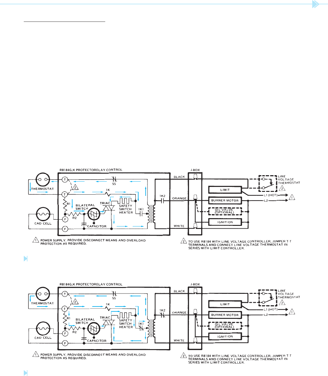
PRIMARY CONTROL
The schematic of a typical primary control is shown
in Figure 39–2. Notice that this control employs
1K2
IGNITION
TRANSFORMER
10,000 VAC
ELECTRODES
ARC
120 VAC
Figure 39–1
Electric-arc ignites oil-fi red furnace.
(Source: Delmar/Cengage Learning)
Figure 39–2
Internal schematic and typical hookup for R8184G. (Courtesy of Honeywell Inc.).
UNIT 39 Oil Burner Controls 355
coil 1K is connected in series with the safety switch
heater at this time.
Figure 39–4 illustrates the operation of the cir-
cuit when relay coil 1K energizes. Notice that both
contacts 1K1 and 1K2 are shown closed. When
contact 1K2 closes, 120 volts is connected to the
burner motor and the ignition transformer. When
contact 1K1 closes, a different current path for the
relay coil and safety heater is provided to the center
tap of the transformer. Relay coil 1K and the safety
switch heater are no longer connected in series.
Notice that one current path is through the thermo-
stat, and 1K relay coil. The current path through
the SBS and triac gate is still provided because the oil
ame has not been ignited as yet and the CAD cell is
still in darkness.
A second current path is provided through the triac
and safety switch heater. If, for some reason, ignition
CIRCUIT OPERATION
To help in understanding how this circuit works, it
will be shown in different stages of operation. In the
circuit shown in Figure 39–3, the thermostat has
just called for heat. The arrows are used to show the
path of current ow through the circuit. The cur-
rent leaves one side of the step-down transformer
and ows through the thermostat contacts. The
current then ows through resistor R1. Because the
CAD cell is in darkness, it has a very high resistance.
This causes most of the voltage to be dropped at the
junction point of R1 and R2. Because the voltage at
this point is greater than 5 volts, the SBS will turn
on and conduct current to the gate of the triac.
When the triac turns on, current is permitted to
ow through relay coil 1K, the safety switch heater,
the triac, and back to the transformer. Notice that
Figure 39–3
Internal schematic and typical hookup for R8184G after thermostat has called for heat. (Courtesy of Honeywell Inc.).
Figure 39–4
Internal schematic and typical hookup for R8184G when relay coil 1K energizes.
(Courtesy of Honeywell Inc.).
356 SECTION 5 Control Components
the voltage drop at the junction of resistors R1 and
R2 becomes very low. Because there is now less
than 5 volts, the SBS is turned off and no current
is conducted to the gate of the triac. This stops the
current ow through the safety switch heater and
the circuit continues to operate until the thermostat
is satis ed.
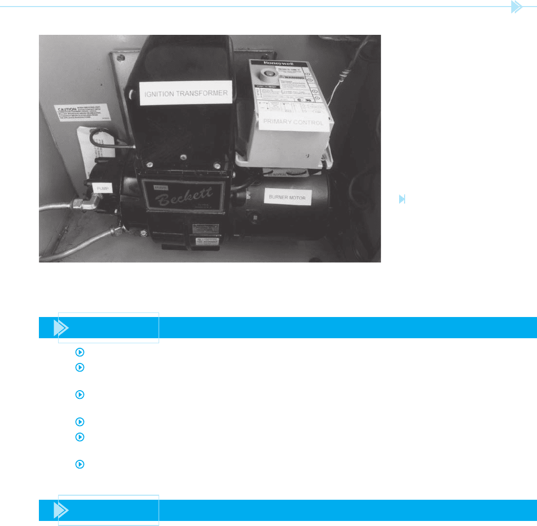
A photograph of a CAD cell used as the ame
detector in an oil furnace is shown in Figure 39–6.
A primary control unit for an oil furnace is shown in
Figure 39–7. A burner assembly with pump, burner
motor, primary control, and ignition transformer is
shown in Figure 39–8.
should not occur, current will continue to ow through
the triac and safety switch heater. This will eventually
cause the bimetal contact SS to open and disconnect
the thermostat circuit. If this should happen, it is nec-
essary to manually reset the primary control with the
reset button located on the control unit.
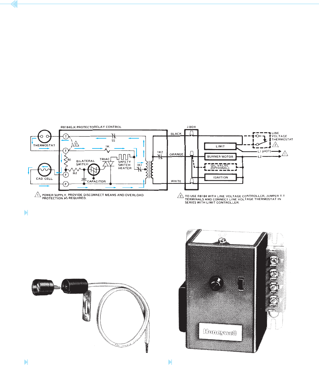
In Figure 39–5, the circuit is shown in its normal
operating condition after ignition. Notice that cur-
rent is still permitted to ow through the 1K relay
coil to keep it energized. The triac, however, has
been turned off. When ignition occurs, the CAD cell
“sees” the light of the ame. This causes its resis-
tance to drop to a low value. When this happens,
Figure 39–5
Internal schematic and typical hookup for R8184G in normal operating condition after ignition. (Courtesy of Honeywell Inc.).
Figure 39–6
CAD cell fl ame detector.
(Courtesy of Honeywell Inc.).
Figure 39–7
Primary control.
(Courtesy of Honeywell Inc.).
UNIT 39 Oil Burner Controls 357
Figure 39–8
Oil burner assembly
with pump, burner
motor, primary
control, and ignition
transformer. (Source: Delmar/
Cengage Learning)
SUMMARY
The primary control controls the major operation of an oil- red heating system.
The primary control must ensure that ignition is established in the combustion chamber
to prevent an accumulation of oil vapor.
Oil- red systems are generally ignited by a high-voltage transformer producing an arc
across two electrodes located near the nozzle.
Most primary controls contain solid-state components.
A CAD cell located in a position close to the ame is used to sense burner igniting by
detecting the light of the ame.
A CAD cell is a solid-state device that lowers its resistance in the presence of light.
KEY TERMS
cadmium sul de cell (CAD cell)
gun-type
primary control
silicon bilateral switch (SBS)

358 SECTION 5 Control Components
REVIEW QUESTIONS
1. What is the function of the ignition transformer?
2. How much voltage is supplied to the electrodes?
3. Are the electrodes permitted to enter into the oil spray?
4. What does enter into the oil spray to cause ignition?
5. What device is controlled by the operation of the triac?
6. What solid-state device controls the ow of gate current to the triac?
7. Does the CAD cell have a high resistance or low resistance when in the presence of
light?
8. How would the circuit operate if the CAD cell were in the presence of light when the
thermostat called for heat?
SECTION 6
Troubleshooting
Using Control
Schematics