Stephen L. Herman, Bennie Sparkman. Electricity and Controls for HVAC-R (6th edition)
Подождите немного. Документ загружается.


Troubleshooting is probably the most important
part of a service technician’s job. Good trouble-
shooting ability will save hours of valuable time and
money. Unfortunately, troubleshooting can be one
of the most confusing aspects of the job if the techni-
cian does not know the basics. Different technicians
use different methods. Most adopt a procedure they
are comfortable with and understand. Some basic
questions that should be considered when trouble-
shooting any type of system are:
• What is the system supposed to do?
• How does it do it?
• What is it doing that it should not be doing, or
what is it not doing that it should be doing?
Knowing the answer to these basic questions will
generally point you in the right direction for deter-
mining the problem.
360
OBJECTIVES
After studying this unit the student should
be able to:
Use a voltmeter to measure voltage
across circuit components
Use an ohmmeter to measure
continuity and component resistance
Use an ammeter to measure circuit
current
Explain the hopscotch method of
troubleshooting
Discuss the use of current transformers
Discuss safety considerations when
using CTs
UNIT 40
Introduction to
Troubleshooting
UNIT 40 Introduction to Troubleshooting 361
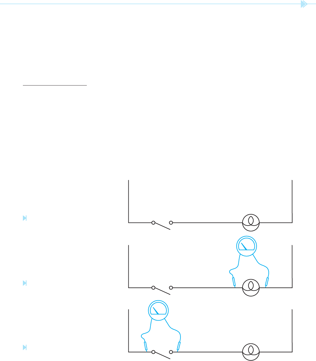
QUESTION 1: Assuming the lamp lament is good,
would the voltmeter shown in Figure 40–2 indicate
0 volts, 120 volts, or some voltage value between 0
and 120?
ANSWER: The voltmeter would indicate 0 volts.
In the circuit shown in Figure 40–2 the switch
and lamp are connected in series. One of the basic
rules for a series circuit is that the voltage drop
across all components equals the applied volt-
age. The voltage drop across each component is
proportional to the amount of resistance of the
component and the amount of current flow. In
the circuit shown in Figure 40-2, there is no cur-
rent flow because the switch is open. Because no
current can flow through the lamp there can be
no voltage drop.
QUESTION 2: If the voltmeter probes were to be moved
across the switch as shown in Figure 40–3 would
the meter indicate 0 volts, 120 volts, or some value
between 0 and 120 volts?
Troubleshooting electric circuits generally
involves the use of electric measuring instru-
ments
. The most common are the voltmeter,
ammeter, and ohmmeter. Understanding how
each of these instruments functions and how to
employ them is one of the keys to developing good
troubleshooting skills. The general use of each will
be discussed in this unit.
THE VOLTMETER
Recall that one de nition of voltage is electrical
pressure. The voltmeter indicates the amount of
potential between two points, in much the same
way a pressure gauge indicates the pressure differ-
ence between two points. In the circuit shown in
Figure 40–1, assume that a voltage of 120 volts exists
between L1 and N. If the leads of a voltmeter were
to be connected between L1 and N, the meter would
indicate 120 volts. Now assume that the leads of the
voltmeter are connected across the lamp, Figure 40–2.
L1 N
Figure 40–1
A voltage of 120 volts exists between
L1 and N. (Source: Delmar/Cengage Learning)
L1 N
V
Figure 40–2
The voltmeter is connected across the
lamp. (Source: Delmar/Cengage Learning)
L1 N
V
Figure 40–3
The voltmeter is connected across the
switch. (Source: Delmar/Cengage Learning)
362 SECTION 6 Troubleshooting Using Control Schematics
voltage drop across the voltmeter resistance it is
generally considered to be zero. Assume the lamp
lament to have a resistance of 50 ohms. Now
assume the voltmeter is a digital voltmeter with
a resistance of 10 million ohms. The total circuit
resistance is 10,000,050 ⍀. The total circuit cur-
rent is 0.000011999 amps (120/10,000,050) or
about 12 microamperes. The voltage drop across
the lamp lament is 0.0006 volts or 0.6 millivolts
(50 ⫻ 12 μA).
QUESTION 4: Assume that the lament of the lamp
is open or burned out. Would the voltmeter in
Figure 40–3 indicate 0 volts, 120 volts, or some
value between 0 and 120 volts?
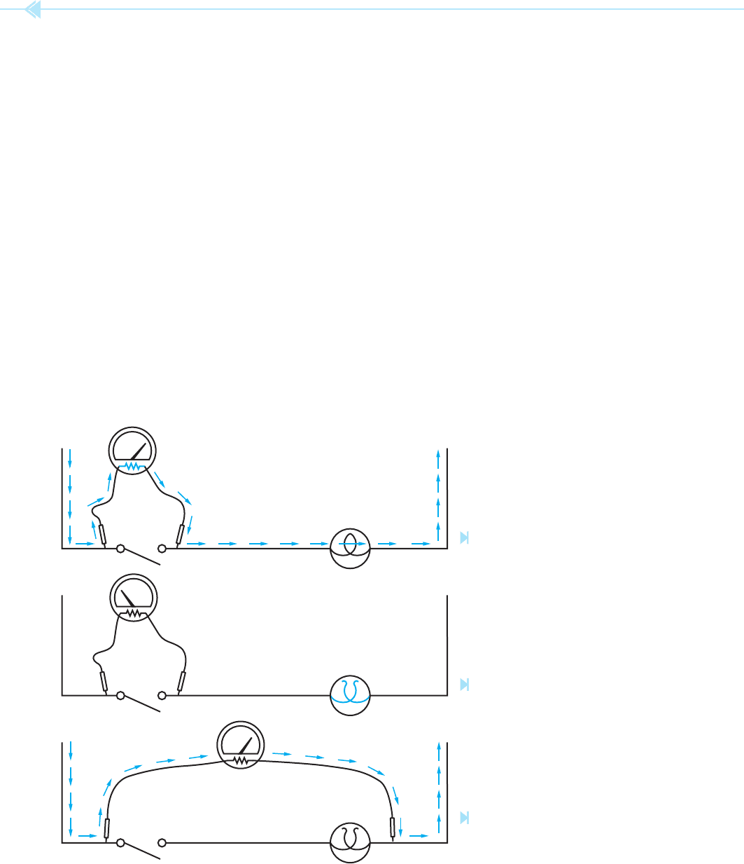
ANSWER: The voltmeter would indicate 0 volts. If the
lamp lament is open or burned out, a current path
for the voltmeter does not exist and the voltmeter
would indicate zero, Figure 40–5. In order for the
voltmeter to indicate voltage, it would have to be
connected across L1 and N so that a complete circuit
through the meter would exist, Figure 40–6.
ANSWER: The voltmeter would indicate 120 volts.
Because the switch is an open circuit, the resistance
is in nite at this point, which is millions of times
greater than the resistance of the lamp lament.
Remember that voltage is electrical pressure. The
only current ow necessary to measure voltage is
the current ow through the meter itself. In this cir-
cuit, the only current path is through the resistance
of the voltmeter and the lamp lament, Figure 40–4.
If the probes of the voltmeter were to be connected
to a wall outlet the meter would indicate 120 volts,
but there would be no current ow except through
the meter itself.
QUESTION 3: If the total or applied voltage in a series
circuit equals the voltage drop across each compo-
nent, why is all the voltage drop across the voltme-
ter resistor and none across the lamp lament?
ANSWER: There is some voltage drop across the lamp
lament because the current of the voltmeter is
owing through it. The voltage drop across the lamp
lament, however, is so small as compared with the
V
L1 N
Figure 40–4
Current fl ows through the meter and lamp
fi lament. (Source: Delmar/Cengage Learning)
Figure 40–6
A complete circuit must exist through the
meter to measure voltage. (Source: Delmar/
Cengage Learning)
L1 N
V
Figure 40–5
If the lamp fi lament is open, no current can fl ow.
(Source: Delmar/Cengage Learning)
L1 N
V
UNIT 40 Introduction to Troubleshooting 363
2. This causes both FR load contacts to close
and connect the fan motor to the 240-volt
line.
3. The moving air of the fan causes ow switch
FL to close.
4. When switch FL closes, power is provided to
the compressor contactor (CC).
5. Both CC load contacts close and supply power
to the compressor motor.
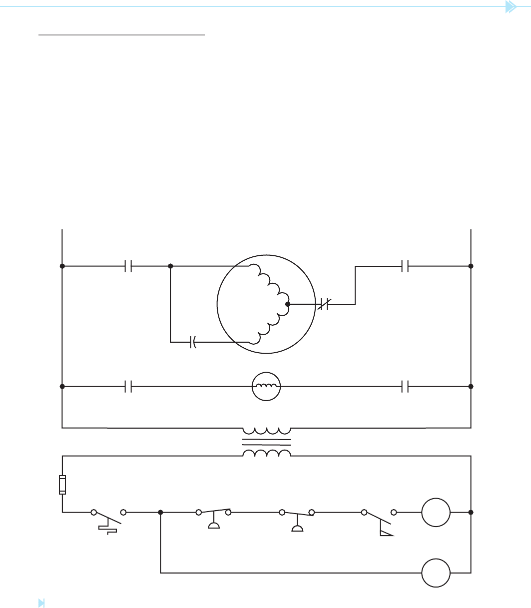
TROUBLESHOOTING WITH
THE VOLTMETER
Before it is possible to troubleshoot a circuit, the
technician must have an understanding of how
the circuit operates normally. The circuit shown
in Figure 40–7 is a basic control circuit for a
compressor. The circuit operates as follows:
1. When the thermostat contacts close, power is
provided to the FR (fan relay) coil.
L2L1
FR FR
THERMOSTAT
FUSE
HP LP FL
TRANSFORMER 240/24
CC
FR
FAN MOTOR
COMPRESSOR
240 VAC
CC CC
OL
C
R
S
Figure 40–7
Basic compressor circuit. (Source: Delmar/Cengage Learning)
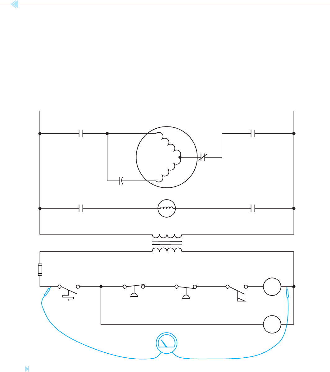
364 SECTION 6 Troubleshooting Using Control Schematics
conditioner will not work. The rst test to be made
is to determine if control voltage is available from
the secondary of the transformer. This can be done
by checking for 24 volts from the thermostat to CC,
Figure 40–8. For the purpose of this example, it will
be assumed that the voltmeter indicated 24 volts.
The next step is to attempt to operate the unit.
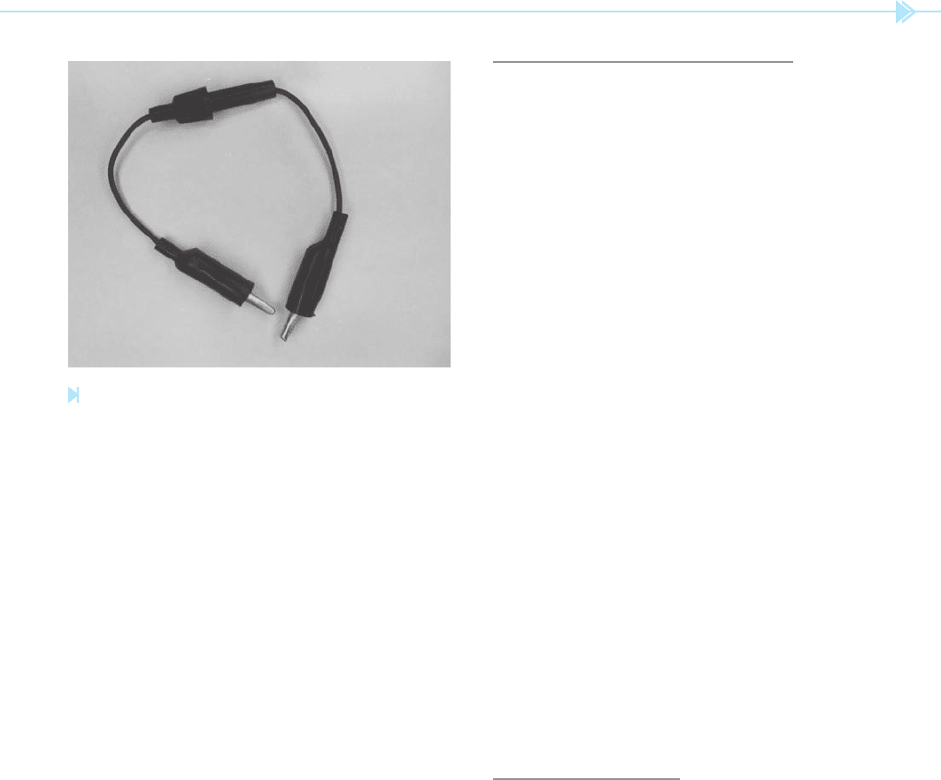
Many service technicians use a jumper to short the
thermostat contacts. When a jumper is used to short
components in a control circuit, a fused jumper
6. High-pressure and low-pressure switches
connected in series with the compressor con-
tactor provide protection for the compressor.
7. When the thermostat opens, the circuit to
both the compressor contactor and fan relay
is broken disconnecting the compressor and
fan from the line.
Assume that a problem has developed with the
unit. The service technician is told that the air
L2L1
FR FR
THERMOSTAT
FUSE
HP LP FL
TRANSFORMER 240/24
CC
FR
FAN MOTOR
COMPRESSOR
240 VAC
CC CC
OL
C
R
S
V
Figure 40–8
Testing the transformer voltage. (Source: Delmar/Cengage Learning)
UNIT 40 Introduction to Troubleshooting 365
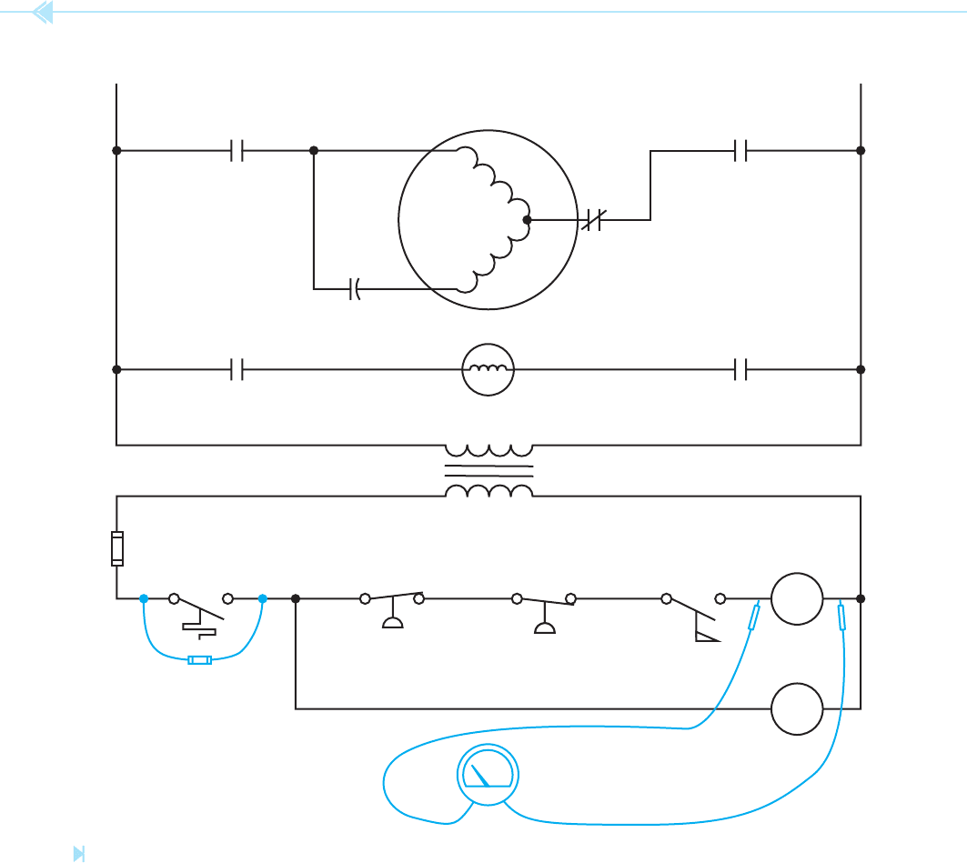
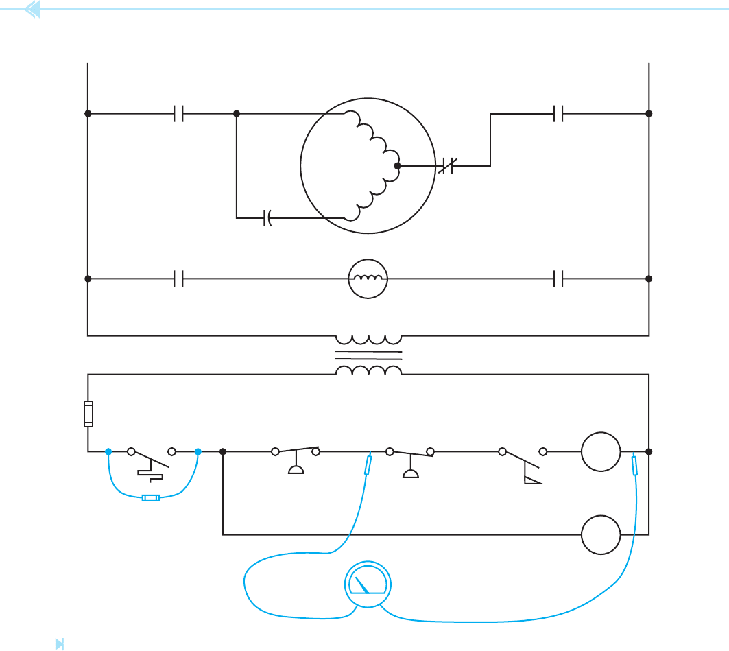
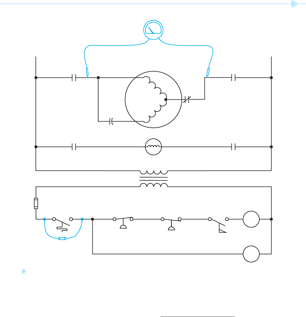
THE HOPSCOTCH METHOD
A very common troubleshooting method is called
the hopscotch method. As the name implies,
you jump from one component to another until the
open part of the circuit is found. In the example in
Figure 40–10, the voltmeter is connected across the
coil of contactor CC. To use the hopscotch method
of troubleshooting, leave one voltmeter probe con-
nected to one side of the transformer and connect
the other probe on the other side of the next compo-
nent in line, Figure 40–11. If the voltmeter indicates
24 volts, it means that the ow switch is open and
preventing the compressor contractor from energiz-
ing. If the voltmeter indicates 0 volts, it means that
there is still an open condition somewhere else in
the circuit that is preventing the voltmeter from
receiving a ow or current. The 0 volt reading does
not mean that contact FL is closed. Contact FL could
be open but there is something else open in the cir-
cuit ahead of it. In this example, it will be assumed
that the voltmeter indicates 0 volt.
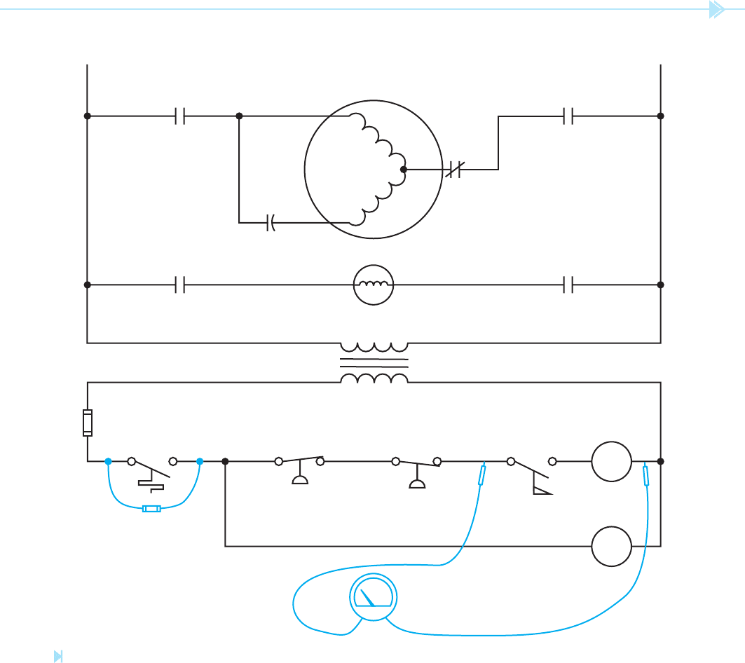
The next step is to hopscotch to the next
component, which is the low pressure switch,
Figure 40–12. If the voltmeter indicates a voltage
of 24 volts, it is an indication that the low pressure
switch is open. If the voltmeter indicates 0 volts,
the voltmeter probe should be moved across the
next component in line. For this example it will be
assumed that the voltmeter indicates a voltage of
24 volts. The next step is to determine if the switch is
defective or if the system is low on refrigerant.
THE OHMMETER
The ohmmeter is generally used in two primary
ways:
1. To measure the amount of resistance in a
circuit.
2. To test a circuit for continuity.
Assume that a service technician is sent on a ser-
vice call. The only information given is that the
air conditioner will not run. Using the same circuit
in the previous example, assume that the techni-
cian places a jumper across the thermostat and
discovers that the condenser fan operates but the
Figure 40–9
Fused jumper for shorting control components.
(Source: Delmar/Cengage Learning)
is recommended, Figure 40–9. The jumper contains
a small amp value fuse such as 3 or 4 amperes. If
the jumper should be accidentally connected across
power, the fuse will blow instantly. Assume then
that the thermostat was jumped; the fan motor
started but the compressor did not.
The next step is to determine what could be the
problem. Looking at the schematic, make mental notes
of what could cause the compressor not to start.
1. CC contactor is defective.
2. Flow switch FL did not close.
3. The low-pressure switch, LP, is open.
4. The high-pressure switch, HP is open.
5. CC load contacts are burned out and not con-
necting power to the compressor.
6. The compressor overload is open.
7. The compressor start capacitor is bad.
8. The compressor motor is bad.
The next logical step is probably to determine if
voltage is being applied to the coil of the compressor
contactor. This can be done by jumping the thermo-
stat and checking across CC coil with a voltmeter,
Figure 40–10.
For this example, it will be assumed that the volt-
meter indicated that there was no voltage applied to
contactor coil CC.
366 SECTION 6 Troubleshooting Using Control Schematics
1. The compressor windings are open.
2. The overload relay is tripped.
Assume that the overload is checked and found
not to be tripped. The next step is to check the
compressor run and start windings for continu-
ity and resistance. This is done by connecting one
probe of an ohmmeter to the common terminal of
compressor does not. Now assume that he discovers
that the compressor contactor is energized. The rst
step would be to test the voltage across the run/
start and common terminals of the compressor,
Figure 40–13. It will be assumed that the voltmeter
indicates a value of 240 volts.
The next step is to make mental notes of what
could cause this problem.
L2L1
FR FR
THERMOSTAT
FUSE
HP LP FL
TRANSFORMER 240/24
CC
FR
FAN MOTOR
COMPRESSOR
240 VAC
CC CC
OL
C
R
S
V
Figure 40–10
Measuring voltage across the compressor contactor. (Source: Delmar/Cengage Learning)
UNIT 40 Introduction to Troubleshooting 367
The resistance reading will generally give some
indication as to the state of the winding, although
trying to determine if a winding is shorted with an
ohmmeter is a guess at best. The actual resistance
of the winding is determined by the size and type of
compressor motor and will probably not be known
the compressor and the other terminal to the run
and start terminals one at a time, Figure 40–14.
The ohmmeter should indicate continuity between
the common terminal and the run terminal and
continuity between the common terminal and the
start terminal. If it does not, it is an indication that
the winding is open.
L2L1
FR FR
THERMOSTAT
FUSE
HP LP FL
TRANSFORMER 240/24
CC
FR
FAN MOTOR
COMPRESSOR
240 VAC
CC CC
OL
C
R
S
V
Figure 40–11
The voltmeter is connected to the next component in line. (Source: Delmar/Cengage Learning)
368 SECTION 6 Troubleshooting Using Control Schematics
The run and start windings should also be tested to
ensure that they are not grounded. This can be done by
connecting one side of the ohmmeter probe to the case
of the compressor and testing for continuity to each
winding, Figure 40–15. The ohmmeter should indicate
in nite resistance if the winding are not grounded.
Another type of ohmmeter, called a megohmmeter
or “megger,” is often used to test the insulation of
by the service technician, but some general guide-
lines can be followed.
1. If the resistance of either winding is extremely
low as compared with the other, there is a
good possibility that the winding is shorted.
2. The start winding should be a little more
resistive than the run winding.
L2L1
FR FR
THERMOSTAT
FUSE
HP LP FL
TRANSFORMER 240/24
CC
FR
FAN MOTOR
COMPRESSOR
240 VAC
CC CC
OL
C
R
S
V
Figure 40–12
The next component in line is tested. (Source: Delmar/Cengage Learning)
UNIT 40 Introduction to Troubleshooting 369
use from 500 to 1,000 volts to supply current to the
circuit being tested. This higher voltage will often
reveal problems that a low voltage will not.
USING AN AMMETER
The ammeter is used to measure the actual amount of
electricity owing in a circuit. This can be extremely
valuable when trying to determine if something
wire, Figure 40–16. The megohmmeter is designed to
measure resistance in the range of millions of ohms.
It is generally used to test the insulation of wire and
also produces a much higher voltage than a standard
ohmmeter. Often, the insulation around wire will
appear to be good when tested with an ohmmeter, but
breaks down when it is subjected to a high voltage.
Ohmmeters generally use from 1.5 to 9 volts to supply
current to the circuit being tested. Meggers generally
L2L1
FR FR
THERMOSTAT
FUSE
HP LP FL
TRANSFORMER 240/24
CC
FR
FAN MOTOR
COMPRESSOR
240 VAC
CC CC
OL
C
R
S
V
Figure 40–13
Testing voltage to the compressor.
(Source: Delmar/Cengage Learning)