Труды Всемирного конгресса Международного общества солнечной энергии - 2007. Том 2
Подождите немного. Документ загружается.

Proceedings of ISES Solar World Congress 2007: Solar Energy and Human Settlement
682
4. CONCLUSION
Taiwan University has been devoted to the development of
low-cost LHP, in cooperation with local industry. A new
manufacturing process for low-cost LHP has been
developed that leads to a cost down to less than 10USD for
a 100W LHP. The present study utilizes the low-cost LHP
to develop a new type of solar water heater. A
thermosyphon which is thermally bonded with a solar
absorber plate is used to absorb solar energy and transfer
the heat upward to the evaporator of the LHP. From that,
the heat is conducted downward to the condenser of the
LHP which is immersed in a hot water tank beneath the
solar collector. The solar water heat thus can be designed in
integral type with streamline shape which is easy to install
and has a good outlook as well as high efficiency. A
prototype was designed and fabricated in the present study.
A preliminary heat transfer test for a single unit of
thermosyphon-LHP combination shows that it is capable of
transferring the absorbed energy downward to the LHP
condenser immersed in a hot water tank. The overall
thermal resistance from the absorber plate to water is
0.34
o
C/W, and that of the LHP part is 0.16
o
C/W. Two
prototypes of the solar water heaters with 50 liters and 80
liters hot water tanks were designed according to the results
of the feasibility test. In addition, an automatic monitoring
system was designed and set up for the performance test of
these two solar water heaters based on the test standard
CNS B7277. The measured overall thermal resistance from
solar absorber plate to water is 0.369
o
C/W. The daily solar
water heater efficiency is 0.503. The present study has
shown that the application of low-cost LHP in solar water
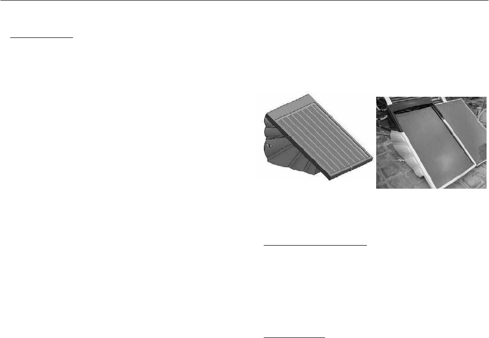
heater is feasible and cost competitive. Figure 13 shows the
outlook of the new product design which is in mass
production. The capacity of water storage is 80L, and the
solar collector area is 1m
2
. CFD analysis has also shown
that this product can stand in a wind speed >60 m/s without
tilt-over or sliding.
Fig. 13: Product design of ISWH.
5. ACKNOWLEDGEMENT
The present study was supported by Energy Bureau,
“Ministry of Economic Affairs”, Taiwan, China, KongLin
Group, and Advanced Thermal Devices, Inc.
6. REFERENCES
(1) B.J.Huang: "Similarity theory of solar water heater
with natural circulation". Solar Energy, Vol.25(2),
pp.105-116 (1980).
(2) B.J. Huang: “Development of a low-cost LHP for
commercial application”. 13
th
International Heat Pipe
Conference (13
th
IHPC), Shanghai, China, September
21-25, 2004.
(3) Bureau of Standards, Metrology ϟ Inspection,
M.O.E.A., R.O.C. CNS B7277: Method of Test for
Solar Water Heater System1989.

PEFORMANCE OF A TWO-PHASE UNGLAZED SOLAR
EVAPORATOR-COLLECTOR
M. N. A. Hawlader*, Ye Shaochun
Department of Mechanical Engineering, National University of Singapore,
9 Engineering Drive 1, Singapore 117576
*Tel: +65-6516 2218, Fax: +65-6779 1459, email: mpehawla@nus.edu.sg
ABSTRACT
In this study, the performance of a two-phase unglazed
solar evaporator-collector in a heat pump solar cooling,
water heating and drying system is investigated. This type
of collector can be locally made and relatively much
cheaper than the conventional collector. Refrigerant
R-134a is used as the working fluid due to the better
thermodynamic and environmental performance. A
transient two-dimensional mathematical model of the
evaporator-collector has been developed to predict
temperature distribution and useful energy gain. A series
of experiments were performed under the meteorological
conditions of Singapore. Both experimental and analytical
results show the fact that the two-phase unglazed solar
evaporator-collector, instead of losing energy to the
ambient, gained a significant amount due to low operating
temperature of the collector. As a result, the collector
efficiency attains a value greater than 1, when
conventional collector equation is used. With this
evaporator-collector, the system can be operated even in
the absence of solar radiation. Experiments with a header
type parallel tube evaporator-collector and serpentine
collector indicate a better performance of serpentine one.
This analysis shows that the two-phase unglazed solar
evaporator-collector has good potential for application in
the tropics.
1. INTRODUTION
In view of the growing global energy needs and concern for
environmental degradation, the possibility of running
thermal system using the energy from the sun is receiving
considerable attention in recent years. In addition, heat
pump is widely used in heating applications. A concept
named direct expansion solar-assisted heat pump
(DX-SAHP) was first proposed in an experimental study by
Sporn and Ambrose[1]. Based on these studies, Chaturvedi
et al.[2] performed an investigation on the steady state
thermal performance of a direct expansion solar-assisted
heat pump and indicated that this system offers significant
advantage in terms of superior thermal performance.
Various studies have been conducted to investigate different
types and applications of direct expansion solar-assisted
heat pump. Hawlader et al.[3] used refrigerant 134a in the
heat pump for water heating application and the evaporator
was used as a solar collector leading to a significant
improvement in COP. Lu et al. [4] used R-22 as the
working fluid under the meteorological condition of
Australia. They also simulated and compared the
performance of air-source heat pump and solar heat pump
in eight cities of Australia. Huang and Lee [5] also
developed a heat pump solar water heater. Hawlader et al.[6]
developed a solar-assisted heat-pump dryer and water
heater. The COP of the system was about 5.0.
Proceedings of ISES Solar World Congress 2007: Solar Energy and Human Settlement
684
Solar evaporator-collector is the essential component in a
direct expansion solar-assisted heat pump system. The
concept of un-glazed solar evaporator collector was first
proposed and investigated by Chaturvedi et al.[7]
The Simple structure of the un-glazed solar collector makes
it an economical type of solar collector. However, its
performance is highly dependent on the environment. Many
authors [8-10] reported that, for the ambient temperature of
above 25°C, the evaporator could be operated at an
elevated temperature. Hawlader et al. [3] performed
analytical and experimental studies on a solar assisted heat
pump using unglazed, flat plate solar collectors, known as
an evaporator-collector, using a steady-state one-
dimensional mathematical model
In current study, the performance of a two-phase unglazed
solar evaporator-collector in a heat pump solar cooling,
water heating and drying system is investigated. The
evaporator-collector is made of a copper absorber plate
coated with black paint with no glazing. Underneath the
plate, serpentine copper tubes are brazed to enable the
refrigerant to flow. This type of collector can be locally
made and relatively much cheaper than the conventional
collector. Refrigerant R-134a is used as the working fluid
due to the better thermodynamic and environmental
performance. A proto-type of the system has been
fabricated and installed at the National University of
Singapore. The three functions, which are cooling, water
heating and drying, can be served simultaneously or
independently. A series of experiments were performed
under the meteorological conditions of Singapore to
validate the model.
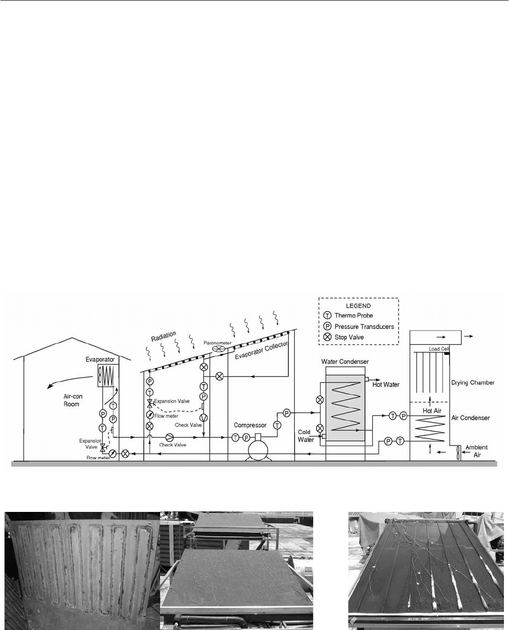
An integrated solar assisted heat pump system was
designed and built, as shown in Fig. 1, and operated in the
meteorological conditions of Singapore. Two
evaporator-collectors were connected in series. A copper
Fig. 1: Schematic diagram of an integrated solar heat-pump system.
Fig. 2: Photograph of the serpentine type evaporator-collector and header type evaporator-collector.
3 SOLAR COLLECTOR TECHNOLOGIES AND SYSTEMS
685
tube of 9.52 mm diameter was soldered at the back of each
absorber plate in serpentine form. Adequate insulations
were provided at the back of the collector but no glass
cover was used on the top surface i.e. unglazed collector.
There is a bypass line from the exit of the first
evaporator-collector to the exit of second
evaporator-collector, which remains closed or open
depending on the solar irradiation. Refrigerant R-134a is
used as the working fluid due to the better thermodynamic
and environmental performance.
A thermostatic expansion valve is used for the system, which
maintains constant superheat at the inlet of the compressor
by regulating the mass flow rate of refrigerant with the help
of a feeler bulb. Actually, the feeler bulb is a remote bulb of
the thermostatic expansion device that controls the degree of
superheat by controlling the pressure. An open
type-reciprocating compressor is used for the system, which
is directly coupled to a three-phase induction motor.
The three applications (air-conditioning, water heating and
drying) of this system can be served simultaneously or
independently. A frequency inverter is utilized to vary the
compressor speed, to have proper matching between the
evaporator load (cooling requirement) and condenser load
(heating requirement) and thus improves the efficiency.
Different motor speeds in different operating conditions
lead to different refrigerant mass flow rate in the
evaporator-collector
The details of the evaporator-collectors are shown in Figure 2.
2.
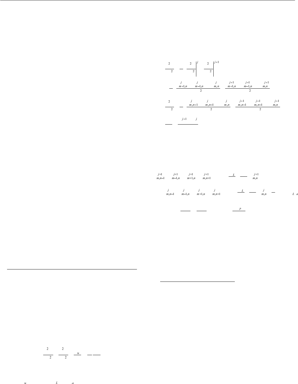
MATHEMATICAL MODELING AND SIMULATION
A transient mathematical model of the system has been
developed. Two-dimensional simulation is applied in the
part of evaporator-collector to obtain more accurate
collector performance prediction. By considering an
element of the collector, a two-dimensional partial
differential equation is developed to describe the collector
performance, as shown in equation 1
1
q
TT T
ktxyδα
∂∂ ∂
++=
∂∂∂
(1)
where
() ( )qI UTTτα=−− and 1τ =
Equation 1 is solved by making use of Crank-Nicholson
method and appropriate boundary conditions.
Using Crank-Nicholson method, the governing equations
for the evaporator-collector are expressed as:
1
2
22
1
2
22
1
2
TTT
xxx
TT TTT T
xx
TT TTT T
T
yy y
TTT
tt
⎛⎞
∂∂∂
⎜⎟
=+
⎜⎟
∂∂∂
⎝⎠
⎛⎞
+− +−
=+
⎜⎟
⎜⎟
ΔΔ
⎝⎠
⎛⎞
+− +−
∂
=+
⎜⎟
⎜⎟
∂Δ Δ
⎝⎠
−∂
=
∂Δ
The Finite difference approximation for the partial
differential equation is derived as:
()
()
2
4
22
4
U
p
TTTT T
rr
U
p
TTTT T IUT
rr r
α
⎛⎞
++++−−−
⎜⎟
⎝⎠
⎛⎞
=− + + + + + − − +
⎜⎟
⎝⎠
where
22
kk
r
xy
δδ
==
ΔΔ
and
c
p
t
ρδ
=
Δ
After setting the initial condition, variation of temperature
distribution on the evaporator-collector can be calculated
by Gauss-Seidel iteration method using the finite difference
approximation.
3.
RESULTS AND DISCUSSION
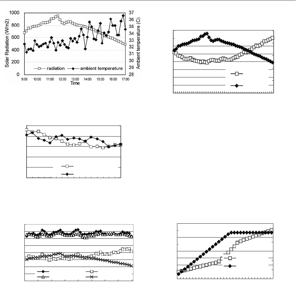
Results were obtained for both simulation and experimental
data. Meteorological data for a typical day in Singapore is
shown in Figures 3.1 and 3.2.
In Fig. 4, predicted useful energy gain (Q
u
) by collector
was plotted against time. Useful energy gain(Q
u
) is the
combination of energy gain from irradiation and the energy
gain from ambient. While the energy gain from ambient,
Q
surrond
is mainly effected by ambient temperature. It shows
that predicted Q
u
has a reasonably good agreement with
experimental values. As seen from Figure 4, Q
u
shows a
slightly declining trend with the reduction of irradiation.
Proceedings of ISES Solar World Congress 2007: Solar Energy and Human Settlement
686
Fig. 3.1: Variation of solar radiation and ambient
temperature with time for a typical day in
Singapore.
0
0.2
0.4
0.6
0.8
1
9:00 10:00 11:00 12:00 13:00 14:00 15:00 16:00 17:00
Time
RH
0
1
2
3
4
5
Wind Speed(m/s)
Relative Humidity
Wind Speed
Fig. 3.2: Variation of relative humidity and wind speed with
time for a typical day in Singapore.
7LPH
(QHUJ\JDLQ:
4XVLPXODWLRQ 4VXUUR QG
4XH[SHULPHQW 4UDGLD WLRQ
Fig. 4: Variation of useful energy gain of the evaporator-
collector.
For high irradiation level, the unglazed solar
evaporator-collector absorbed almost equivalent energy
from both irradiation and the ambient. However, it
absorbed much more energy from the ambient than that
from irradiation when the level of radiation is lower than
600W/m
2
,as shown in Figures 3.1 and 4. This property
enables the unglazed evaporator-collector to supply
sufficient energy even at cloudy day and night.
0
0.2
0.4
0.6
0.8
1
1.2
1.4
1.6
9:00 10:0011:0012:001 3:0014:0015 :0016:0017:00
Time
Efficiency
0
200
400
600
800
1000
Radiation(W/m2)
Efficiency
Radiation
Fig. 5: Variation of solar collector efficiency and solar
radiation with time.
Solar collector efficiency is defined as the ratio of the
useful energy gain to the total incident solar radiation. As
shown in Figure 4, the total useful energy gain is relatively
constant when radiation is fluctuating. This feature of
unglazed solar evaporator collector makes the collector
efficiency to decline when radiation increases. However,
due to the energy gain from ambient, the collector
efficiency can be more than 1 at the condition of low level
of radiation.
0
5
10
15
20
25
30
35
40
0 4 8 12 16 20 24
Tube length(m)
Plate temperature(C)
0
0.2
0.4
0.6
0.8
1
1.2
Vapour quality
plate T(mean)
Quality
Fig. 6 Mean plate temperature and vapour quality against
the tube length.
Fig. 6 shows the simulation result of mean plate
temperature and vapour quality against the tube length
when the radiation at 700W/m
2
and ambient temperature at
30
o
C. At two phase flow region, where vapour quality is
less than 1, plate temperature is much lower than the
ambient temperature. This temperature difference causes
the energy gain from ambient. However, plate temperature
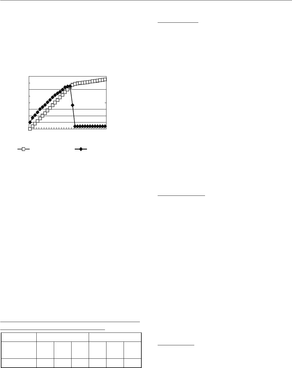
3 SOLAR COLLECTOR TECHNOLOGIES AND SYSTEMS
687
rapidly increased and exceed the ambient temperature when
refrigerant reached pure vapour region.
As shown in figure 7, the increasing rate of useful energy
gain dropped dramatically due to the heat transfer
coefficient dropped to a lower value in single phase
(saturated vapour) region.
0
500
1000
1500
2000
2500
3000
3500
4000
0 4 8 12 16 20 24
Tube length(m)
Useful energy gain(W)
0
500
1000
1500
2000
Heat transfer coeff(W/m2
K)
Usefull heat heat tansfer coeff
Fig. 7: Heat transfer coefficiency in the tube and useful
energy gain against the tube length.
It was also found that the length of two phase flow region
reduced when radiation increased or mass flow rate reduced.
By adjusting the mass flow rate, the ratio of two phase flow
region length to the total length can be controlled in
different meteorological condition.
Besides the serpentine type solar evaporator-collector,
header type is another common type for solar collector. The
performance of these to types of two-phase unglazed solar
evaporator-collector is shown as follows:
Both the experiments were conducted under radiation level
at 700W/m
2
. At the same radiation level and for same
collector area, the serpentine type collector has higher
efficiency than header type with parallel tubes, as clearly
shown in Table 1.
TABLE 1: COMPARISON OF BOTH SERPENTINE
TYPE AND HEADER TYPE COLLECTOR
Area:1.5m
2
Serpentine type Header type
Compressor
Speed, rpm
450 600 750 450 600 750
Efficiency 1.18 1.11 1.08 0.87 0.85 0.83
4. CONCLUSIONS
A two-dimensional mathematical model of the
evaporator-collector has been developed to predict
temperature distribution and useful energy gain. To validate
the model, experiments were conducted under the
meteorological conditions of Singapore. Both experimental
and analytical results show the fact that the two-phase
unglazed solar evaporator-collector, instead of losing energy
to the ambient, gained a significant amount from the
surrounding air due to low operating temperature of the
collector. Analytical results show that both heat transfer
coefficient and energy gain in two phase region of collector
are much higher than those in single phase (saturated vapour)
region. The length of two phase region increases while the
radiation decline. Experiments with a header type parallel
tube evaporator-collector and serpentine collector indicate a
better performance of serpentine one. This analysis shows
that the two-phase unglazed solar evaporator-collector has
good potential for application in the tropics.
5. NOMENCLATURE
Abbreviation Description Unit
c
p
Specific heat capacity kJ/K
I Solar radiation W/m
2
k Thermal conductivity W/mK
m Mass flow rate kg/s
Q
u
Useful energy gain W
t Time s
T Temperature K
U
L
Heat loss coefficienct W/ m
2
K
α Solar absorptance dimensionless
τ Transmittance dimensionless
ρ Density kg/m
3
δ Plate thickness m
Subscripts
a air
6. REFERENCES
(1) P. Sporn and E. R. Ambrose, The Heat Pump and Solar
Energy Proc. Worm Symp. Appl. Solar Energy, Phoenix,
Arizona, Nov 1-5, 1955

Proceedings of ISES Solar World Congress 2007: Solar Energy and Human Settlement
688
(2) S.K. Chaturvedi, D.T.Chen and Kheireddine, A,
Thermal performance of a direct expansion solar
assisted heat pump. Energy Conversion and
Management, v 39, n 3-4, Feb.-March 1998, p 181-91
(3) M.N.A. Hawlader, S.K. Chou, and M.Z. Ullah, The
performance of a solar assisted heat pump water
heating system, Applied Thermal Engineering, Volume
21, Issue 10, Pages 1049-1065
(4) Lu, A., Charters, W.W.S. and Chaichana, C. Solar heat
pump systems for domestic hot water, Solar Energy Vol.
73, No. 3, pp. 169–175
(5) B.J. Huang and C.P. Lee, Long-term performance of
solar-assisted heat pump water heater, Renewable
Energy, Volume 29, p633–639.
(6) M.N.A. Hawlader, S.K. Chou, K.A. Jahangeer, Rahman,
S.M.A. and Eugene Lau K. W. Solar-assisted heat-
pump dryer and water heater, Applied Energy, Volume
74, Issues 1-2 , Pages 185-193
(7) S.K.Chaturvedi, F.B.G. Chata and A.Almogbel,
Analysis of a direct expansion solar assisted heat pump
using different refrigerants, Energy Conversion and
Management, v 46, n 15-16, Sept. 2005, p 2614-24
(8) E.A. Kush, Performance of heat pumps at elevated
evaporating temperatures with application to solar input.
Journal of Solar Energy Engineering 102 (1980), pp.
203–210.
(9) G.L. Morrison and D. Gilliaert, Unglazed solar
collector performance characteristics. Journal of Solar
Energy Engineering 114 (1992), pp. 194–200.
Abstract-INSPEC
(10) M.P. O'Dell, J.W. Mitchell and W.A. Beckman,
Design method and performance of heat pumps with
refrigerant filled collectors. Transactions of the
ASHRAE 89 (1) (1983), pp. 519–525.

AN EXPERIMENTAL STUDY ON THE HEAT TRANSFER CHARACTERISTICS OF THE
HYBRID SOLAR RECEIVER FOR A DISH CONCENTRATING SYSTEM
MyeongCheol Kang
Korea Institute of Energy Research
P.O. Box 305-343
Daejeon, Korea
mckang21@kier.re.kr
JinSoo Kim
Korea Institute of Energy Research
P.O. Box 305-343
Daejeon, Korea
jinskim@kier.re.kr
YongHeack Kang
Korea Institute of Energy Research
P.O. Box 305-343
Daejeon, Korea
yhkang@kier.re.kr
NackJoo Kim
Seoul National University of Technology
P.O. Box 139-743
Seoul, Korea
nackjoo@snut.ac.kr
SeongYeon Yoo
BK21 Mechatronics Group at Chungnam National
University
P.O. Box 305-764
Daejeon, Korea
syyooh@cnu.ac.k
JinHeack Kim
BK21 Mechatronics Group at Chungnam National
University
P.O. Box 305-764
Daejeon, Korea
mcple80@cnu.ac.kr
ABSTRACT
The dish/stirling system is used to convert solar energy
directly to electricity. Therefore, in order to improve
economical efficiency of a solar power system, the stirling
unit must be operated continuously. For continuous
operation of the stirling unit, the receiver must be
continuously provided with thermal energy from solar as
well as additional combustion heat. It is possible for a
hybrid solar receiver system equipped with an additional
combustion system to be operated 24 hrs/day.
A hybrid solar receiver adopted heat pipe heat transfer
mechanism was designed and manufactured to supply the
thermal energy to the stirling engine.
The hybrid receiver system was tested in a gas-only mode
to investigate heat transfer characteristics at inclination
angles varying from 0 deg to 30 deg and the ratios of the
aperture diameter to cavity diameter of 0(closed cavity) and
1(open cavity). The increase in temperature in the case of a
closed cavity is higher than an open cavity, but
temperatures in all cases rise in proportion to the input
thermal load. In the case of the open cavity, the thermal
resistances decreased in proportion to input thermal load
and inclination angle, but it was 1~3 times higher than
those of the closed cavity. The evaporation and
condensation heat transfer coefficient increased linearly
with input thermal load. The evaporation heat transfer
coefficient increased in proportion with input thermal load
and inclination angle in the closed cavity.
1. INTRODUCTION
A dish type solar concentrating system consists of a
parabolic concentrator and a receiver. In order to achieve
Proceedings of ISES Solar World Congress 2007: Solar Energy and Human Settlement
690
high temperature from solar energy, it is essential to
efficiently reflect the solar rays in the concentrator and to
minimize thermal losses in the cavity receiver. For
idealizing the design of a receiver, the characteristics of the
concentrator, the shape and size of flux distributions in the
focal plane, should be considered. The design of the solar
receiver is a key technology and one of the most difficult
properties of developing dish-type solar power systems.
However, the solar energy has a fundamental disadvantage
of inconsistent power density, depending on weather
conditions and seasons.
The hybrid receiver system is required to improve
economical efficiency of a solar power system using solar
and additional combustion heat. The new concept of
developing a receiver for continuous operation of the stirling
unit is required and technology of the heat pipe is presented.
The heat pipe allows a separation of the different heat
transfer surfaces, absorber surface, combustion surface, and
stirling head[1]. A heat pipe receiver has the advantage of
excellent heat transfer mechanisms, and non-uniform heat
fluxes can be tolerated much better than with the tube type
receiver[2]. Laing D. successfully developed and tested for
the hybrid heat pipe receiver. Maximum system efficiency
in solar-only mode had been 16%, in gas-only mode 17%,
and in hybrid mode 15%. Hartenstine, et al. designed a
hybrid receiver based on numerical simulations and small
scale tests, and fabricated a hybrid receiver with the 3
burners to operating simultaneously[4].
In this paper, a hybrid solar receiver adopted heat pipe heat
transfer mechanism was designed and manufactured to
supply solar energy as well as additional combustion heat
to the stirling engine. The hybrid receiver system was
tested in gas-only mode to investigate the heat transfer
characteristics.
2. EXPERIMENTAL APPARATUS AND METHODO-
LOGY
2.1 Hybrid Solar Receiver
The hybrid receiver using heat pipe was manufactured to
supply thermal from solar in cavity and combustion heat in
out surface wall. The heat pipe was designed for a total
thermal load of 35 kW in the operating temperature range
700ଇ to 800ଇ vapor temperature and used working fluid
of sodium. The heat pipe has a double walled vessel and
consists of a solar heat input, combustor heat input, and
heat output to stirling head, it is realized by using three
different heat transfer surfaces.
The cavity diameter is 216 mm and the diameter of the
outer heat pipe mantle is 315 mm. The outer heat pipe
mantle serves as a heat transfer surface for the gas heat
flow. The heat pipe container is made of stainless steel. All
capillary structures are made of a stainless steel screen and
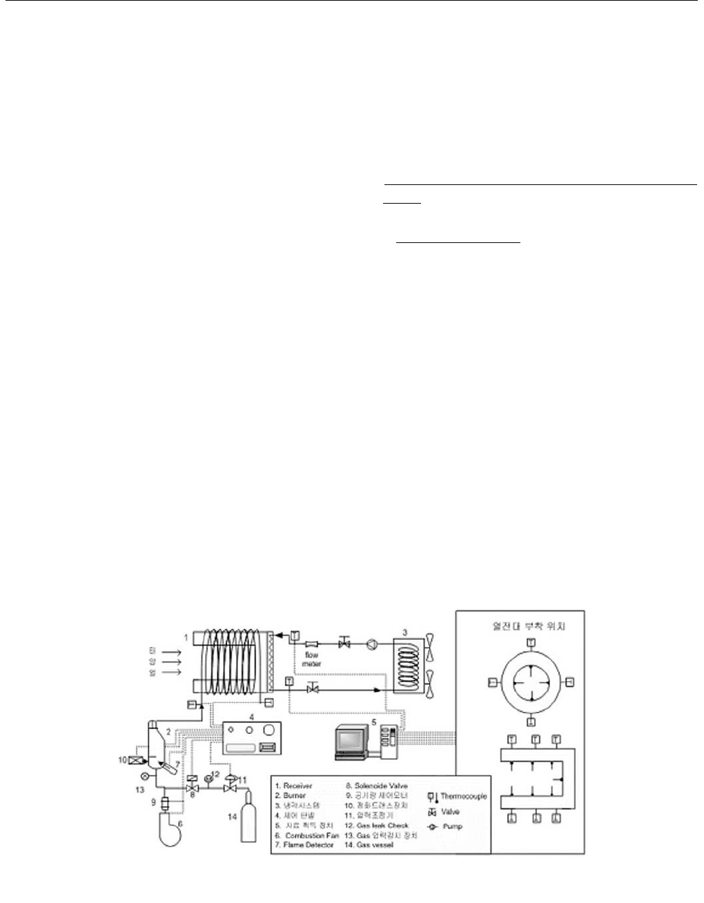
spotted in place. Fig. 1 shows the schematic of experimental
apparatus and receiver thermocouples locations. A picture
Fig. 1: Schematic of experimental apparatus and receiver thermocouples locations.
3 SOLAR COLLECTOR TECHNOLOGIES AND SYSTEMS
691
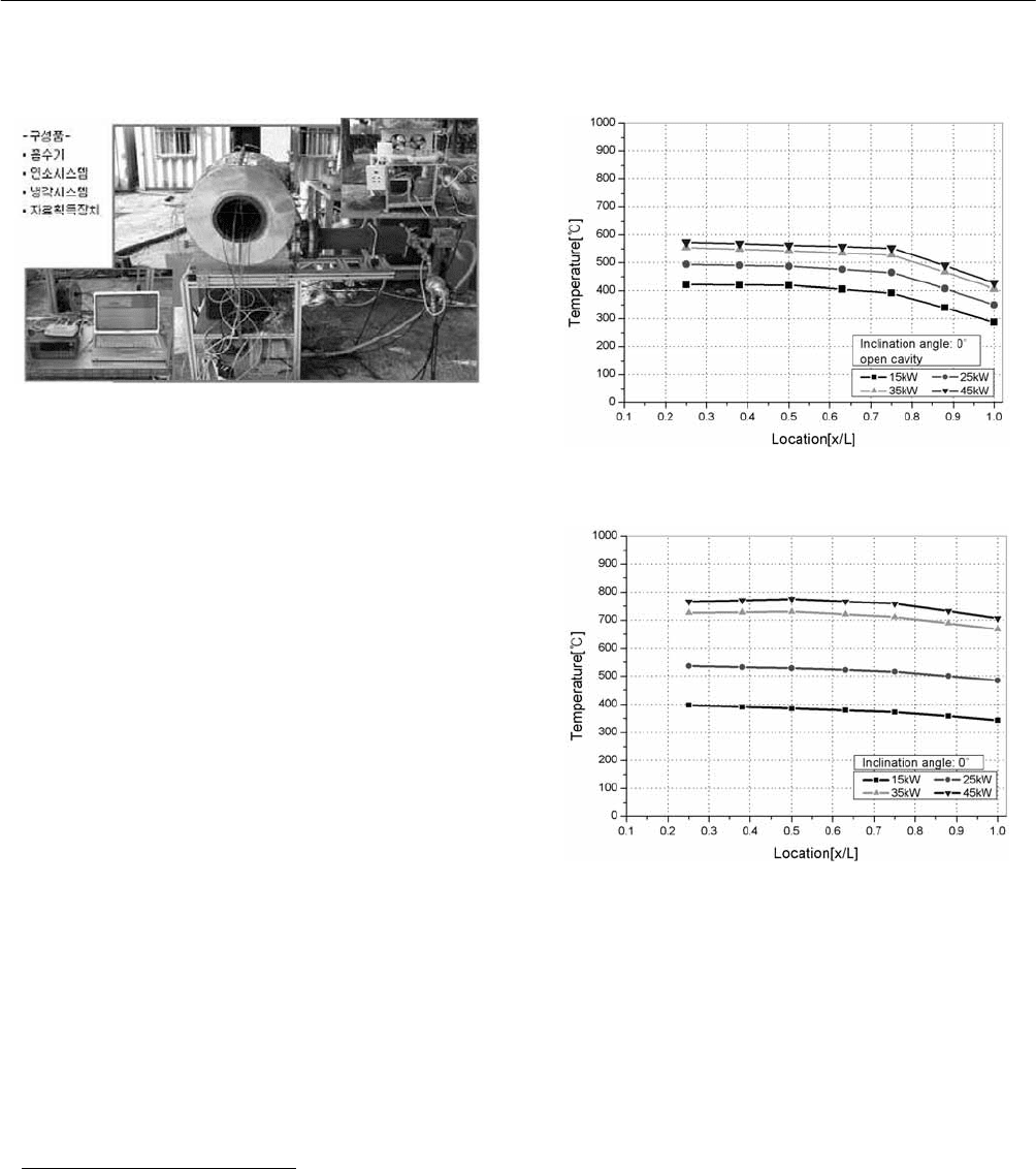
of the experimental apparatus with receiver, combustion
system, and cooling system is shown in Fig. 2.
Fig. 2: Experimental apparatus with receiver, combustion
system, and cooling system.
The natural gas burner will supply the high temperature of
combustion to the hybrid heat pipe receiver. The
combustion systems consist of a burner, combustion fan,
flame detector, ignition transformer, etc. The burner will be
fired tangentially into the combustion chamber. The burner
is equipped with a air damper motor and gas solenoide
valve to control the flowrate of air and gas. The flame
holder is located in the side part of the heat pipe outer wall
and combustion heat is circulated through the flow path
line.
The hybrid receiver performance will be verified through
ground testing by gas fired heat. To investigate heat transfer
characteristics from the hybrid receiver, it was tested at
inclination angles varying from 0 deg to 30 deg(cavity
facing down). The ratios of the aperture diameter to cavity
diameter of 0(closed cavity) and 1.0(open cavity) were
used as well. This paper has been constructed to measure
temperature variation in cavity surface and to analyze
thermal resistances, and the evaporation and condensation
heat transfer coefficient in all cases(open and closed
cavity).
3. RESULTS AND DISCUSSIONS
Fig. 3 and Fig. 4 show the temperature distribution along
length of cavity surface at 0 deg in an open and closed
cavity. The increase in temperature in the case of a closed
cavity is higher than an open cavity, but temperature in all
cases rise in proportion to the input thermal load. The
temperature difference along the length of the open cavity
surface was higher than that of the closed cavity.
Fig. 3: Temperature distribution along length of cavity
surface at 0 deg(open cavity).
Fig. 4: Temperature distribution along length of cavity
surface at 0 deg(closed cavity).
Fig. 5 and Fig. 6 show the thermal resistances variation
with increasing input thermal load. In case of the open
cavity, the thermal resistances decreased in proportion to
input thermal load and inclination angels, but it was 1~3
times higher than those of the closed cavity.
The variation of evaporation heat transfer coefficient in all
cases is shown in Fig. 7 and Fig. 8, respectively. Fig. 9 and
Fig. 10 show variation of condensation heat transfer
coefficient in all cases. The evaporation and condensation
heat transfer coefficient increased linearly with input
thermal load in the open cavity. The evaporation heat
transfer coefficient in proportion with input thermal load
and inclination angle in the closed cavity. The condensation