Wai-Fah Chen.The Civil Engineering Handbook
Подождите немного. Документ загружается.


Simulation in Hydraulics and Hydrology 38-13
must have a number placed in columns 16 and 17 of the first row of the STRUCT statement. This
number, 01, should be the same as the structure number on the RESVOR standard control
statement.
4. The RUNOFF Standard Control statement for area 1 is used to obtain the runoff from the 0.021
square miles. The CN and t
c
for the developed conditions replace the numbers used in Example 38.1.
5. A RESVOR Standard Control statement is used to have the hydrograph calculated from area 1
routed through the pond structure. This is done by placing “01” (the pond structure number) in
columns 19 and 20. The routed hydrograph is placed in a computer memory location by placing
a number 1 through 7, not already used, in column 23. Therefore, a 2 is placed in column 23.
6. The INCREM and COMPUT Executive Control statements are the same as in Example 38.1. With
these statements, the peak discharge rate and time will be computed, as well as the peak elevation
in the pond. In order for the flow in pond to be analyzed, the last cross section must be specified
as the pond structure. This is done by placing the cross section number of the culvert in columns
20 and 21 of the COMPUT statement. Again, ENDJOB is the last statement.
Output
The output format is the same as in Example 38.1 because the output options in columns 61–70 are the
same, with the addition of the options chosen for the RESVOR statement. A condensed version of the
output is shown on Fig. 38.5 and Table 38.3.
Summary
As in Example 38.1, the summary table on the last page of the output summarizes all of the information
obtained. This table contains the developed runoff information for area 1 and for peak flow and elevation
through the pond. The pond used to control the runoff from area 1 is checked to see if it is sufficient.
The peak discharge elevation is 783.07 feet for the 10-year storm. This indicates that the pond does not
overtop for the storm event modeled.
Example 38.3
Description
The entire watershed is analyzed to determine the amount of runoff from the 0.3 square miles. This
example incorporates the same area as Example 38.1, but also includes the runoff from the three other
subbasins under existing conditions from the entire watershed. The watershed is subdivided into
4 subbasins as shown on Fig. 38.1. Area 1 has been analyzed with and without the pond in the two
previous examples. There is a 1-acre lake in the middle of the watershed, which takes in the runoff from
TA B L E 38.2 Stage-Storage-
Discharge Relationship for Pond
in Example 38.2
Stage Discharge Storage
780.5
781.0
781.5
782.0
782.5
783.0
783.5
784.0
784.5
785.0
785.5
786.0
786.5
787.0
0
2
4
8
12
15
20
23
28
30
32.5
35
36
40
0.0
0.004
0.014
0.019
0.046
0.88
1.33
1.67
2.07
2.46
2.85
3.23
3.49
4.52
© 2003 by CRC Press LLC

38-14 The Civil Engineering Handbook, Second Edition
SUMMARY TABLE 1 - SELECTED RESULTS OF STANDARD AND EXECUTIVE CONTROL
INSTRUCTIONS IN THE ORDER PERFORMED (A STAR(*) AFTER THE PEAK DISCHARGE TIME AND RATE (CFS) VALUES INDICATES
A FLAT TOP HYDROGRAPH A QUESTION MARK(?) INDICATES A HYDROGRAPH WITH PEAK AS LAST POINT.)
SECTION/
STRUCTURE
ID
STANDARD
CONTROL
OPERATION
DRAIN.
AREA
RAIN
TABLE
#
ANTEC
MOIST
COND
MAIN
TIME
INCREM
(HR)
PRECIPITATION
RUNOFF
AMOUNT
(IN)
PEAK DISCHARGE
BEGIN
(HR)
AMOUNT
(IN)
DURATION
(HR)
ELEV.
(FT)
TIME
(HR)
RATE
(CFS)
RATE
(CSM)
ALTERNATE 1 STORM 1
XSECTION 1 RUNOFF 0.02 7 2 0.10 .0 3.23 6.00 2.48 — 3.05 46.63 2220.4
STRUCTURE 1 RESVOR 0.02 7 2 0.10 .0 3.23 6.00 2.47 783.07 3.45 15.72 748.8
FIGURE 38.5 Output from Example 38.2.
© 2003 by CRC Press LLC

Simulation in Hydraulics and Hydrology 38-15
Areas 1, 2, and 3. The discharge from this lake is routed through a channel to the outlet of the watershed.
Table 38.4 shows the stage-storage-discharge relationship for the 1-acre lake.
The hydrologic input data is the same as in the previous examples. This refers to the rainfall data for
the SCS Type II distribution and the rainfall amount for a 10-year recurrence interval in Indianapolis.
Another storm, the 100-year 12-hour event, was used to demonstrate how easy it is to add additional
storms.
Calculations
Table 38.5 contains the information from the computation of the CN and t
c
values. The longest t
c
is for
drainage area 4. The total time of concentration for the entire watershed is 1.05 hours.
Computer Input
The input file from Example 38.1 is edited to include the information for the additional subbasins. A
reach is added by using the tabular control XSECTN and the corresponding codes. The STRUCT table
is changed to reflect the 1-acre lake. The Standard Control statements, RUNOFF and ADDHYD, are
needed for the additional subbasins. The area, CN, and t
c
are described on each RUNOFF statement.
COMPUT and ENDCMP statements are used to add the 100-year storm event values. The ADDHYD
statement is used to combine two hydrographs computed from the respective RUNOFF statement. The
ADDHYD is used because there are only two input hydrographs entries for each RUNOFF statement.
The input is shown in Fig. 38.6.
For example, the hydrographs from areas 1, 2, and 3 are combined and routed through the 1-acre lake
before adding runoff from area 4. Therefore, two ADDHYD statements are used to combine the hydro-
graphs computed from the pond in area 1 and the runoff from area 2. Another ADDHYD statement is
used to combine the previously obtained hydrographs with the hydrograph computed from area 3. The
1-acre pond in area 3 is then described by a RESVOR statement. This statement refers to STRUCT 02
for the stage-storage-discharge relationship. The runoff from all three subbasins is routed through the
TABLE 38.3 Summary of Example 38.2
Location
Peak
Discharge
(cfs)
Runoff
Amount
(in.)
Water Surface
Elevation (ft)
Time to
Peak (hr)
Area 1 46.63 2.48 — 3.05
Pond 15.72 2.47 783.07 3.45
TA B L E 38.4 Stage-Storage-
Discharge Relationship for the
1-Acre Lake in Example 38.3
Stage Discharge Storage
773.0
773.5
774.0
774.5
775.0
775.5
776.0
776.5
777.0
777.5
778.0
0.0
3.0
5.0
7.0
9.0
11.0
13.0
19.0
116.0
325.0
656.0
0.0
0.34
0.86
1.33
1.87
2.41
3.03
3.56
4.37
5.17
5.96
© 2003 by CRC Press LLC

38-16 The Civil Engineering Handbook, Second Edition
pond by placing a “1,” the combined hydrograph number, in column 19 of the RESVOR statement. The
discharge from the pond is then routed through a channel to the outlet of the watershed. The routing is
described by a REACH statement which refers to XSECT 006. The XSECT is the stage-discharge and area
relationship for the 2050-foot channel. The relationship is computed by using the channel cross section
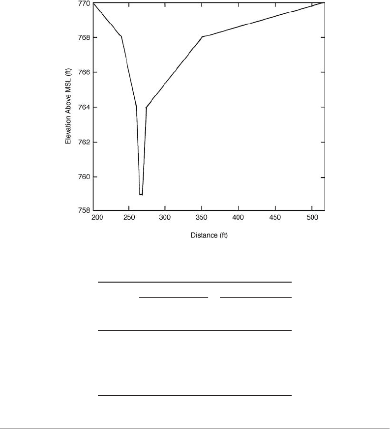
shown in Fig. 38.7. The RUNOFF statement is then used to describe the runoff from area 4. Finally, the
hydrograph from the REACH and area 4 runoff are added together with the ADDHYD statement.
The Executive Control statements are the same as those used in the previous two example problems,
except the last cross section number used must be placed in columns 20 and 21 and the additional
COMPUT and ENDCMP. The COMPUT statements require the input of the initial and final cross
sections that are to be analyzed. Because the ADDHYD was the last Standard Control statement, its cross
section number (columns 14 and 15) is placed in columns 20 and 21 of the COMPUT statement.
Output
The type and amount of output can be controlled by input options on the JOB record and by the output
options on the Standard Control records. All of the output options on the Standard Control statements
were left blank because only a summary table is desired. To accomplish this, SUMMARY is placed in
columns 51–57 of the JOB statement. The output is shown in Fig. 38.8.
Summary
From the summary table of the output shown in Fig. 38.8, it is determined that, for a 10-year storm, the
peak discharge is 233 cfs, which occurs after 3.71 hours. For the 100-year 12-hour storm, the peak
discharge is 361 cfs with a time to peak at 6.46 hours. Output from each subbasin can be inspected to
determine the amount it contributes to the overall runoff from the watershed. The outflow from drainage
areas 1, 2, and 3 are routed through the 1-acre pond and then through a channel. The reach had very
little effect on the time to peak or the discharge. The channel would have to be much wider and longer
for any attenuation to be realized. The results are also summarized below in Table 38.6.
TABLE 38.5 Curve Numbers and Times of Concentration for Example 38.3
Drainage Area Area (acres) Land Use CN Area * CN
Drainage Area 2
2
Total
36
11
21
68
Residential
Commercial
Open Area
Composite curve number
86
94
74
3096
1034
1554
5684
84
Drainage Area 3
3
Total
19
7
N/A
26
Residential
Commercial
Open Area
Composite curve number
86
94
1634
658
2292
88
Drainage Area 4
4
Total
28
37
16
81
Residential
Commercial
Open Area
Composite curve number
86
94
74
2408
3478
1184
7070
87
© 2003 by CRC Press LLC

Simulation in Hydraulics and Hydrology 38-17
JOB TR-20 SUMMARY NO PLOTS
TITLE EXAMPLE 3 - ENTIRE WATERSHED
TITLE PROPOSD CONDITIONS
5RAINFL 7 0.05
800.01 0.03 0.04 0.06
8 0.08 0.10 0.13 0.17 0.22
8 0.64 0.78 0.84 0.87 0.90
8 0.92 0.94 0.96 0.98 0.99
8 1.0 1.0 1.0 1.0 1.0
9 ENDTBL
2 XSECTN 6 1.0 770.0
8 759.0 0.0 0.0
8 760.0 15.09 5.0
8 761.0 51.53 12.0
8 762.0 110.34 21.0
8 763.0 194.31 32.0
8 764.0 306.33 45.0
8 765.0 372.72 71.0
8 766.0 670.69 121.0
8 767.0 1208.35 195.0
8 768.0 2034.72 293.0
8 769.0 2751.61 455.0
8 770.0 4579.98 723.0
9 ENDTBL
3 STRUCT 1
8 773.0 0.0 0
8 773.5 3.0 0.34
8 774.0 5.0 0.86
8 774.5 7.0 1.33
8 775.0 9.0 1.87
8 775.5 11.0 2.41
8 776.0 13.0 3.03
8 776.5 19.0 3.56
8 777.0 116.0 4.37
8 777.5 325.0 5.17
8 778.0 656.0 5.96
9 ENDTBL
6RUNOFF 1 1 1 0.021 93 0.24 AREA 1
6RUNOFF 1 2 2 0.106 84 0.96 AREA 2
6RUNOFF 1 3 3 0.041 88 0.68 AREA 3
6 ADDHYD 4 4 1 2 4
6 ADDHYD 4 5 3 4 1
6 RESVOR 2 01 1 2 LAKE
6 REACH 3 6 2 3 2050 REACH
6RUNOFF 1 7 4 0.127 87 1.01 AREA 4
6 ADDHYD 4 8 3 4 5
ENDATA
7 INCREM 6 0.1
7 COMPUT 7 1 8 0.00 3.23 6 7 21110-YR
ENDCMP 1
7 COMPUT 7 1 8 0.00 5.24 12 7 211100-YR
ENDCMP 1
ENDJOB 2
FIGURE 38.6 Input from Example 38.3.
© 2003 by CRC Press LLC
38-18 The Civil Engineering Handbook, Second Edition
38.4 The HEC-HMS Model
Uses of HEC-HMS
HEC-HMS is a precipitation-runoff simulation model developed by the U.S. Army Corps of Engineers
Hydrologic Engineering Center (HEC) that is a “new generation” software to supercede the HEC-1 Flood
Hydrograph Package. Similar to HEC-1, HEC-HMS can be used: (1) to estimate unit hydrographs, loss
rates, and streamflow routing parameters from measured data and (2) to simulate streamflow from
historical or design rainfall data. Several new capabilities are available in HEC-HMS that were not
available in HEC-1: (1) continuous hydrograph simulation over long periods of time and (2) distributed
runoff computation using a grid cell depiction of the watershed. Capabilities for snow accumulation and
melt, flow-frequency curve analysis, reservoir spillway structures, and dam breach are under development
for HEC-HMS but not yet incorporated.
HEC-HMS consists of a graphical user interface, integrated hydrologic analysis components, data
storage and management capabilities, and graphics and reporting facilities. The program features a
completely integrated work environment including a database, data entry utilities, computation engine,
FIGURE 38.7 Cross section of reach through drainage area 4.
TA B L E 38.6
Summary of Results for Example 38.3
Drainage
Area
6-Hour Storm Event 12-Hour Storm Event
Time of
Peak
(hours)
Peak
Discharge
(cfs)
Time of
Peak
(hours)
Peak
Discharge
(cfs)
1
2
3
Reach
4
Outlet
3.05
3.60
3.37
3.73
3.63
3.71
46.64
80.62
46.00
127.71
107.55
232.79
5.97
6.43
6.22
6.47
6.46
6.46
46.93
125.86
63.91
201.82
159.03
360.85
© 2003 by CRC Press LLC

Simulation in Hydraulics and Hydrology 38-19
SUMMARY TABLE 1 - SELECTED RESULTS OF STANDARD AND EXECUTIVE CONTROL
INSTRUCTIONS IN THE ORDER PERFORMED (A STAR(*) AFTER THE PEAK DISCHARGE TIME AND RATE (CFS)
VA L UES INDICATES A FLAT TOP HYDROGRAPH A QUESTION MARK(?) INDICATES A HYDROGRAPH WITH PEAK AS LAST POINT.)
MAIN
TIME
INCREM
(HR)
SECTION/
STRUCTURE
ID
STANDARD
CONTROL
OPERATION
DRAIN.
AREA
RAIN
TABLE
#
ANTEC
MOIST
COND
PRECIPITATION
RUNOFF
AMOUNT
(IN)
PEAK DISCHARGE
BEGIN
(HR)
AMOUNT
(IN)
DURATION
(HR)
ELEV.
(FT)
TIME
(HR)
RATE
(CFS)
RATE
(CSM)
ALTERNATE 1 STORM 1
XSECTION 1 RUNOFF 0.02 7 2 0.1 0 3.23 6 2.48 3.05 46.63 2220.4
XSECTION 2 RUNOFF 0.11 7 2 0.1 0 3.23 6 1.71 3.6 80.62 760.6
XSECTION 3 RUNOFF 0.04 7 2 0.1 0 3.23 6 2.02 3.37 46 1121.9
XSECTION 4 ADDHYD 0.13 7 2 0.1 0 3.23 6 1.83 3.5 90.94 716
XSECTION 5 ADDHYD 0.17 7 2 0.1 0 3.23 6 1.88 3.43 136.16 810.5
STRUCTURE 1 RESVOR 0.17 7 2 0.1 0 3.23 6 1.87 777.04 3.61 130.97 779.6
XSECTION 6 REACH 0.17 7 2 0.1 0 3.23 6 1.88 762.21 3.73 127.71 760.1
XSECTION 7 RUNOFF 0.13 7 2 0.1 0 3.23 6 1.94 3.63 107.55 846.9
XSECTION 8 ADDHYD 0.30 7 2 0.1 0 3.23 6 1.91 3.71 232.79 789.1
ALTERNATE 1 STORM 2
XSECTION 1 RUNOFF 0.02 7 2 0.1 0 5.24 12 4.43 5.97 46.89 2232.7
XSECTION 2 RUNOFF 0.11 7 2 0.1 0 5.24 12 3.49 6.43 125.86 1187.4
XSECTION 3 RUNOFF 0.04 7 2 0.1 0 5.24 12 3.89 6.22 63.91 1558.8
XSECTION 4 ADDHYD 0.13 7 2 0.1 0 5.24 12 3.65 6.4 143.16 1127.3
XSECTION 5 ADDHYD 0.17 7 2 0.1 0 5.24 12 3.71 6.3 202.98 1208.2
STRUCTURE 1 RESVOR 0.17 7 2 0.1 0 5.24 12 3.7 777.21 6.34 202.33 1204.3
XSECTION 6 REACH 0.17 7 2 0.1 0 5.24 12 3.71 763.07 6.47 201.82 1201.3
XSECTION 7 RUNOFF 0.13 7 2 0.1 0 5.24 12 3.79 6.46 159.03 1252.2
XSECTION 8 ADDHYD 0.30 7 2 0.1 0 5.24 12 3.74 6.46 360.85 1223.2
FIGURE 38.8 Output from Example 38.3.
© 2003 by CRC Press LLC
38-20 The Civil Engineering Handbook, Second Edition
and results reporting tools. A graphical user interface allows the user seamless movement between
different parts of the program. The HEC Data Storage System (DSS) [HEC, 1993] allows the transfer of
data between HEC programs. The data are identified by unique labels called PATHNAMES, which are
specified when the data are created or retrieved. For example, a hydrograph computed by HEC-HMS
can be labeled and stored in DSS for later retrieval as input to HEC-RAS. The DSS program has several
utility programs for manipulating data. HEC-HMS is an easier tool to develop a hydrologic model for
first time users because of its graphical user interface. Those familiar with and who routinely use HEC-1
may be frustrated with the set-up and complexity of running design storm events with user defined
cumulative rainfall distributions. The more complex the hydrologic model is, the more liable the program
is to crashing. It is anticipated that these problems will be improved upon with each new release of
HEC-HMS. The graphics and reporting facilities is a very valuable tool that saves time and makes the
presentation of results easy to produce.
Summary of HEC-HMS Input Structure
A project serves as a container for the different parts that together form the complete watershed model
in HEC-HMS. The three components required for a hydrologic simulation are: (1) Basin Model,
(2) Meteorologic Model, and (3) Control Specifications. A project file may contain more than one of
these three components and is useful for running scenario analysis.
Each run of the model combines a basin model, meteorologic model, and control specifications. The
user should be cautious, as some of these components may not be compatible with each other, depending
on methods and time intervals chosen. Runs can be re-executed at any time to update results when data
in a component is changed. The Run Manager is used to manage and execute runs, proportionally adjust
flow or precipitation results, and save or start the basin model in differing states.
Basin Models
The physical representation of watershed or basins and rivers is configured in the basin model. Hydrologic
elements are connected in a dendritic network to simulate runoff processes. Available elements are:
(1) subbasin, (2) reach, (3) junction, (4) reservoir, (5) diversion, (6) source, and (7) sink. Computation
proceeds from upstream elements in a downstream direction. Hydrologic elements are added to the
model by dragging the appropriate icon from the element palette to the schematic in the Basin Model
screen. Elements are connected to each other within the stream network from upstream to downstream
elements. Elements may also be duplicated and deleted within the Basin Model Screen.
When developing a precipitation-runoff model using HEC-HMS, boundaries of the basin are initially
identified. Most often, the basin is subdivided into smaller subbasins depending on the study objectives,
drainage pattern, and other factors. Points where runoff information is needed are identified. The model
can be structured to produce hydrographs at any desired location. As different areas of a large basin may
have different hydrologic response characteristics, it is important to select an appropriate computational
time interval and subdivide the watershed so that lumped parameters provide a reasonable depiction of
the subbasins.
There are several methods that may be used in HEC-HMS to compute surface runoff. These are based
on: (1) initial and constant excess precipitation, (2) SCS curve number, (3) gridded SCS curve number,
(4) and Green and Ampt. The one-layer deficit and constant model can be used for simple continuous
modeling. The five-layer soil moisture accounting model can be used for continuous modeling of complex
infiltration and evapotranspiration environments.
Several methods are included for transforming excess precipitation into surface runoff. Unit
hydrograph methods include the Clark, Snyder, and SCS technique. User-specified unit hydrograph
ordinates can also be used. The modified Clark method, ModClark, is a linear quasi-distributed unit
hydrograph method that can be used with gridded precipitation data. An implementation of the kinematic
wave method with multiple planes and channels is also included.
A variety of hydrologic routing methods are included for simulating flow in open channels. Routing
with no attenuation can be modeled with the lag method. The traditional Muskingum method is included.
© 2003 by CRC Press LLC

Simulation in Hydraulics and Hydrology 38-21
The modified Puls method can be used to model a reach as a series of cascading level pools with a user-
specified storage-outflow relationship. Channels with trapezoidal, rectangular, triangular, or circular cross
sections can be modeled with the kinematic wave or Muskingum-Cunge method and an 8-point cross
section.
Meteorologic Model
Meteorologic data analysis is performed by the meteorologic model and includes precipitation and
evapotranspiration. Seven different historical and synthetic precipitation methods are included: (1) User
Hyetograph, (2) User Gage Weighting, (3) Inverse-Distance Gage Weighting, (4) Gridded Precipitation,
(5) Frequency Storm (6) Standard Project Storm – Eastern US, and (7) SCS Hypothetical Storm. These
methods are summarized in Table 38.7. One evapotranspiration method is included in the model.
The four historical storm methods and the Gage Weights and User-Specified Hyetograph Methods for
Synthetic Precipitation require entry of time-series precipitation data into the program. Time series data
is stored in a project at a gage. Gage data has to be entered only once. The gages are owned by the project
and can be shared by multiple basin or meteorologic models. The gage data is also stored in the DSS file
created for the project and may be accessed by other projects.
An example of implementing time-series precipitation gage data in HEC-HMS would be using the
Illinois State Water Survey (ISWS) Bulletin 70 rainfall depths with the Huff Rainfall Distributions. The
Huff Rainfall Distribution for a 24-hour design storm event falling over an area of less than 10 square
miles does not vary with different design frequency events. For this reason, the Huff 3
rd
Quartile Distri-
bution may be entered as a precipitation gage using the cumulative storm percent precipitation data from
0–1 over the 24 hour design storm event duration. However, the Huff Rainfall Distributions are given
in cumulative storm percent distributions rather than cumulative time series distributions that HEC-
HMS accepts for precipitation gage data. Therefore, the cumulative storm percent distributions must be
converted to time series precipitation distributions before being entered into HEC-HMS. The Huff
Distributions in this example is specifically for northeastern Illinois (Huff and Angel).
Using the User-Specified Hyetograph precipitation method, this precipitation gage may be assigned
to the subbasins in the model. When running the simulation, the precipitation may be weighted in the
Run Manager to correspond to different design frequency events. The weighted precipitation is the depth
of rainfall for a given design storm event.
Control Specifications
The control specifications set the starting date and time of a run as well as the ending date and time.
The time interval, also called the computation step, is also included.
TABLE 38.7 HEC-HMS Meteorologic Model Precipitation Methods
Precipitation Method Explanation
Historical Precipitation User-specified hyetograph Precipitation data analyzed outside of the program
Gage weights Uses Precipitation data from rainfall gages
Inverse-distance gage weighting Precipitation data from rainfall gages can be used to
proceed when missing data is encountered
Gridded precipitation method Uses radar rainfall data
Synthetic Precipitation Frequency storm Uses statistical data from technical sources to produce
balanced storm with given excedence probability
Standard project storm Implements regulations for precipitation when estimating
the standard project flood
SCS hypothetical storm Implements the primary precipitation distributions for
design analysis using Natural Resource Conservation
Service (NRCS) criteria
User-specified hyetograph Used with a synthetic hyetograph resulting from analysis
outside the program
© 2003 by CRC Press LLC
38-22 The Civil Engineering Handbook, Second Edition
Preparation of Input Data
Preparation of input data can be divided into the following requirements and functions for using the
SCS Methodology in HEC-HMS:
1. Prepare a schematic drawing that conveniently identifies the locations, drainage areas, curve numbers
(CN), lag times (t
L
), and reach lengths for the watershed. It should display all alternate structural
systems together with the routing and evaluation reaches through which they are to be analyzed.
2. List the tabular data to support the requirements of the Basin Model. This may consist of structure
data, stream cross section data, source or sink data and diversion data.
3. Establish the Control Specifications based on the time duration of the storm event to be simulated.
4. Develop a Meteorological Model to be used in the watershed analysis. This may require importing
synthetic or historical rainfall data or developing synthetic rainfall distributions within HEC-HMS.
The starting and ending time and date of the Meteorological Model, as well as the time interval,
should be set in conjunction with the Control Specifications.
Calculations
For a large watershed it may be necessary to divide the watershed into subbasins. Each subbasin is
determined by finding the different outlet points or design points within the watershed, then finding the
area contributing to those points.
1. Area. The area of each subbasin in square miles (mi
2
).
2. Curve Number. The curve number (CN) for each subbasin.
3. Lag Time. The lag time (t
L
) is specified for each subbasin. Lag time (t
L
) is 0.6 times the time of
concentration (t
c
).
The program is currently only set up to use English units.
HEC-GeoHMS Applications
HEC-GeoHMS has been developed as a geospatial hydrology tool kit for engineers and hydrologists with
limited GIS experience. It combines the functionality of ArcInfo programs into a package that is easy to
use with a specialized interface.
The program allows users to visualize spatial information, document watershed characteristics, perform
spatial analysis, delineate subbasins and streams, construct inputs to hydrologic models, and assist with
report preparation. Working with HEC-GeoHMS through its interfaces, menus, tools, buttons, and con-
text-sensitive online help, in a windows environment, allows the user to effectively create hydrologic inputs
that can be used directly with HEC-HMS. It is intended that these hydrologic inputs provide the user
with an initial HEC-HMS model. The user can estimate hydrologic parameters from stream and watershed
characteristics, gaged precipitation, and streamflow data. The user has full control in HEC-HMS to modify
the hydrologic elements and their connectivity to more accurately represent field conditions.
HEC-HMS Example
A 60-acre basin in the Chicagoland area is modeled to determine the adequacy of a stormwater detention
basin to which the area drains. This analysis will use SCS methodologies to determine the runoff
hydrograph characteristics with the Illinois State Water Survey (ISWS) Bulletin 70 rainfall depths and
the Huff rainfall distribution for the 100-year 24-hour design storm event. The 60-acre basin is composed
of 40 acres of residential area and 20 acres of commercial area.
Hydrologic Input Data
The hydrologic parameters of the two subbasins within the 60-acre basin are given in Table 38.8.
The stormwater detention basin and control structure were sized based on the DuPage County, Illinois
stormwater detention requirements. The runoff from the developed area must be released at 0.1 cfs per
acre. The elevation-storage-discharge relationship for the detention basin is given in Table 38.9.
© 2003 by CRC Press LLC